(source: Electronics World, Mar. 1966)
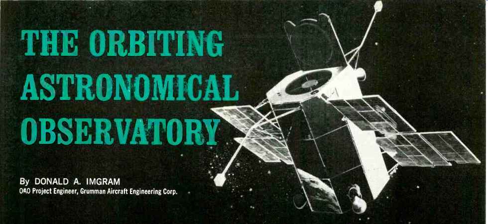
By DONALD A. IMGRAM [OAO Project Engineer, Grumman Aircraft Engineering Corp.]
Probably the most complex satellite built to date, the Orbiting Astronomical Observatory uses the latest electronic techniques to enable scientists to see the universe without interference.
THE Orbiting Astronomical Observatory (OAO) Is the largest, heaviest, and most electronically complex satellite being built under NASA's unmanned observatory program. Astronomy is the OAO's mission, and why NASA should be willing to invest over one hundred million dollars, literally in pursuit of the stars, is not too difficult to understand. All heavenly bodies emit energy at frequencies spanning the electromagnetic spectrum. But the atmosphere which surrounds the earth is a hazy, shimmering veil which absorbs much of the radiation which reaches us from outer space, and only a small portion of the incident radiation is unaffected as it attempts to penetrate the atmospheric barrier. Hence, all current astronomical theories are based almost exclusively on information received by ground observers through a narrow optical "window." Just how much present concepts will be shaken when man can observe the entire universe from an unobstructed vantage point high above the atmosphere is a matter of speculation, but who amongst us could have imagined the contrast between the two photo graphs making up Fig. 1? Similar revelations undoubtedly await the scientists preparing experiments for use on board the OAO, once detection equipment is placed outside the earth's atmosphere where the view will be unobstructed compared with terrestrial observation as shown in Fig. 2.
The OAO
Each OAO, and it is expected that as many as ten launches will be made over the course of the next decade, is composed of two main elements. These are the spacecraft itself and the associated experimental package.
The spacecraft system consists of four electronic subsystems. These are the stabilization and control, data-processing, communications, and power supply subsystems. The functional interplay of each can best be understood by detailing the operation of the satellite after it is inserted into ES in tended orbit. Immediately following booster separator, the stabilization and control system halts the tumbling motion induced by separation forces and begins the initial stabilization and orientation process by seeking and acquiring the sun. Both of these functions are accomplished simultaneously by two different kinds of sensors. The first is a system of three rate gyros that senses tumbling rates about the three spacecraft control axes pitch, yaw, and roll). In the second system, error signals a-e generated by a system of eight "coarse" solar sensors. These are silicon solar cells which when illuminated produce an output that is a cosine function of the angle of incident sunlight on the cell. The eight cells have hemispherical fields of view and are installed such that four provide pitch axis error information while the other four sense yaw motion. No roll control data is provided by the solar sensors. Two of the four eyes for each axis are paired on the front (anti-sun) and rear (sun-pointing) faces of the satellite. The polarity of one cell in each pair is reversed with respect to d at of LE mate, and the outputs of each pair are summed algebraically. The resultant composite signals are roughly sinusoids with the zero (null) crossing points corresponding to zero displacement of the spacecraft from the sun line. Driving signals in the form of error rate and error displacement are hence available and can be used to position the observatory so that at the conclusion of the coarse solar sensing and the rate stabilization phase, the spacecraft is aligned with the sun line. All spacecraft torquing during this phase is accomplished using the high-thrust gas-jet system whose operation is similar to those used in the Mercury and Gemini spacecraft.
Ultimately, the error angle will be reduced to zero and the spacecraft will eventually approach a limit cycle motion of ±2 degrees with a residual rate less than 0.03 degree per second. At this time the spacecraft will have its rear face pointing towards the sun.
Mounted on the rear lice of the observatory is a solar-cell "disable" eye having a restricted field of view (±-10 degrees).
Also affixed to a common fine-pointing assembly are eight additional solar cells. Their function is to provide finer solar-sensing control signals which are used until the spacecraft alignment to the sun line is maintained at ±0.25 degree. Upon achieving the fine solar pointing, the spacecraft begins one of the more challenging stabilization operations that the OAO will be called upon to perform. Termed the "roll search" maneuver, its success depends upon proper functioning of the spacecraft's star trackers, the most-critical components on board the OAO.
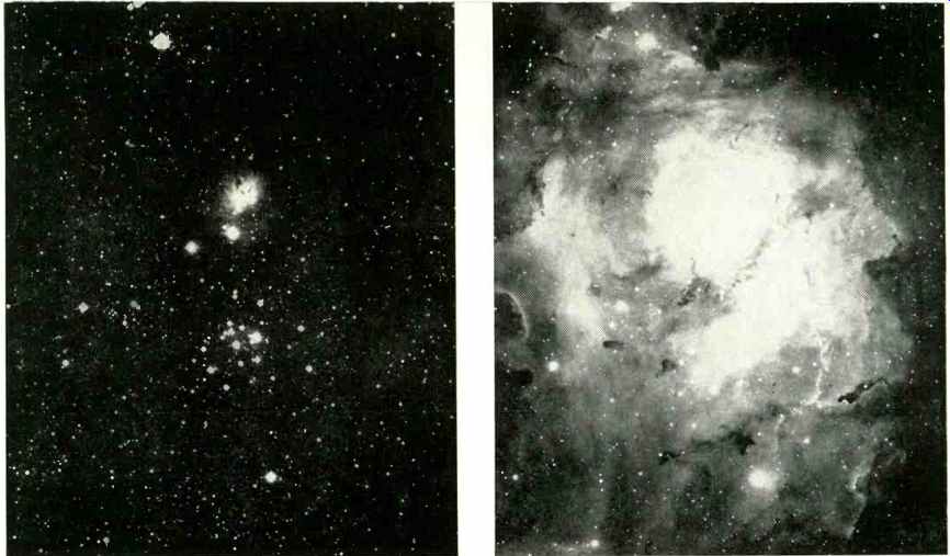
---- Fig. 1. A hint of things to come is shown in this pair of photographs
of the Sagittarius Constellation. The two pictures are identical except
the one made using near ultraviolet light (right) discloses considerable
detail not re corded by the visible light emanating from the same source.
Many similar spectacular pictures will be made by OAO.
Six gimballed star trackers are employed on the OAO, and each is an electro-mechanical/optical device used for the detection, acquisition, and tracking of selected "guide" stars.
Guide stars chosen for the OAO total 31 in number, all having an apparent brightness (S-4 response) of second magnitude or brighter. Operation of a tracker is shown in Fig. 3.
The heart of the device is a 3.5-inch-diameter aluminized beryllium mirror with a focal length of 5 inches. Light entering the telescope-like barrel is reflected off the main mirror onto a prism beam splitter having two secondary plane mirrors offset at an angle of 45 degrees with respect to each other. The offset arrangement permits splitting the incident light into two beams, each of which is used to provide error data about a specific spacecraft control axis (i.e., pitch and roll). The two beams subsequently pass through slits in two orthogonal vibrating reeds and illuminate the cathode surface of a ten-stage photomultiplier. Since one reed vibrates at 350 cps and the other at 450 cps, appropriate circuitry can be used to obtain two-axis control information which facilitates automatic tracking of the guide stars. Filtered outputs from the photomultiplier are synchronously demodulated to yield d.c. voltages whose polarity is a function of phase (direction of displacement of the star image) and whose amplitude is a function of the displacement of the star from the center of the tracker's one-square-degree field of view.
Star-tracker usage begins immediately upon the completion of the fine sun-pointing mode. After the observatory settles into the +- 0.25 degree limit cycle, the roll gyro output is biased to induce a roll search motion about the sun line.
While the OAO is rolling, each tracker sweeps out a one-degree-wide circle on the celestial sphere. Careful pre-selection of gimbal angles-each tracker can be gimballed through 45 degrees on each axis-is performed before launch on ground computers such that at a specific and unique roll angle, all non-occulted star trackers simultaneously detect guide stars. When this occurs, the trackers generate star-presence signals which cause the gyro bias to be removed and allow the trackers to lock onto and track the stars. Sub sequent observatory control is accomplished using stellar control, the solar sensors and gyros serving no further purpose.
All experimentation will obviously not be done with the OAO aligned with the sun line; hence, the observatories are provided with a capability for "slewing" to any arbitrary position in space. Imagine that the spacecraft is aligned with the sun line and that it is desired to reorient the OAO to a position 30 degrees away, say to point the main experiment telescope at a star in the region of Orion. The first required operation is that ground operators at the OAO Central Control Station at Goddard Space Flight Center in Greenbelt, Maryland develop a series of spacecraft commands on a digital computer. These commands will be sent by teletypewriter to one of the three OAO remote-control stations located at Rosman, North Carolina; Quito, Ecuador; and Santiago, Chile. These sites were chosen and equipped with special OAO ground-support equipment because at least one of these stations has a 10-minute r.f. contact with the satellite once every 100-minute orbit. In turn, the remote stations relay the appropriate commands to the observatory. When received on board the spacecraft, the commands are routed to the data processing subsystem.
The means by which the OAO slews from one region of the sky to another are three "coarse" inertia wheels. Inertia wheels, positioned one on each control, are simple a.c. motors which are accelerated and braked as a result of commands sent from the ground. When, for example, the pitch wheel is accelerated, the spacecraft will be caused to rotate about its pitch axis but in an opposite direction in accordance with the principle of conservation of angular momentum. Braking the wheel will cause the spacecraft to cease rotation. By careful calibration of the wheel's inertia properties, acceleration, and braking characteristics, it is possible to accurately predict the slewing actions of the spacecraft in response to wheel motion and hence to orient the OAO to any desired position in space.
The observatory is also equipped with a set of three "fine" inertia wheels which are used to maintain the satellite in a stabilized attitude once the experiment is pointed at the region of interest in the celestial sphere. When supplied with signals directly from the star trackers, the wheels can stabilize the spacecraft to any arbitrary position in inertial space with an accuracy of +-1 minute of arc and restrict drift off this pointing to rates less than 15 arc seconds in 50 minutes of time. Some later spacecraft will be equipped with a "fine error sensor" as part of the main experiment optics. Use of this device will enable future OAO's to be accurately attitude stabilized to less than ±0.1 second of arc.
Spacecraft Commands
Commands may be sent to the OAO as either "real-time" or "delayed-mode" (stored) commands. Real-time commands are used when the observatory is within line-of-sight of a ground station and are executed immediately. Delayed-mode commands may also be executed during line-of-sight contacts (at some time after their initial decoding on board the spacecraft), but generally the delayed commands are placed into memory storage for subsequent execution after the satellite terminates its ground contact. The recognition by the spacecraft as to what type of command has been received is accomplished in the command decoder and distributor portion of the primary processor. A unique feature of the OAO is its ability to verify commands transmitted from the ground. To understand how this operation takes place, it is necessary to review the OAO's command format. The entire OAO data-processing system is digital in nature. Commands are sent to the OAO as a series of four 32-bit command messages. The four words consist of the first and second command words, and the first and second verification words. Verification words are the "ones" complement of the command words, meaning that, for example, if the first command word began its message by the binary bits "11010," the first verification word would be registered as "00101." This format is employed so that on-board verification of received commands can be accomplished by comparing the command word and the verification word on a bit-by-bit basis. Only if an exact comparison of the bits can be made is the command acted upon by the satellite.
Commands are received by the OAO's command receiver at a 1-kc. rate. The spacecraft's system clock, which is a crystal-controlled sine-wave oscillator supplying a fundamental clock frequency of 1.6 mc., provides the basic observatory timing reference. A shaper-driver network forms the clock signal into a square wave and transfers the resultant waveform to a ten-stage frequency divider. Outputs from the frequency divider are decoded to provide clock pulses and bit gate for use by all OAO equipments. Received commands are synchronized to the primary processor's 50-kc. bit time rate and are verified on board as well as retransmitted to the ground for a further verification (or "echo check"). When it is desired to store a command for later use, the message is entered into the OAO's command-storage unit.
Command-storage capability is included to facilitate quad redundant storage of 128 two-word commands (verification words are not stored since they are of no further use after a command has been validated). The storage medium consists of the MARS (Multi-Aperture Reluctance Switch) devices. These are tiny ferrite cores which allow random-access, non-destructive readout capability. The observatory also incorporates a 200,000-bit data-storage unit which is used to record both spacecraft as well as experiment data. Again, the MARS devices are utilized. The entire data memory can be used to store information in a non-redundant fashion, or the memories can be "halved" to permit redundant storage of 100,000 bits of data. The Gemini computer was derived from the OAO data-processing unit.
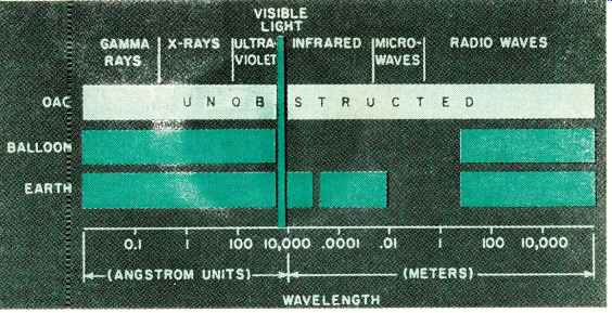
Fig. 2. The earth's atmosphere absorbs certain portions of the electromagnetic
spectrum.
Once above this medium with the OAO, total spectrum observation is very easily attained.
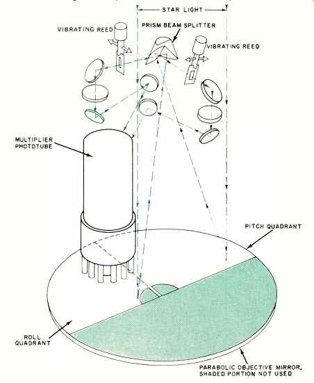
Fig. 3. The star tracker splits incident starlight into two beams, each
modulated at a different frequency by the vibrating reeds to provide error
data about a specific axis.
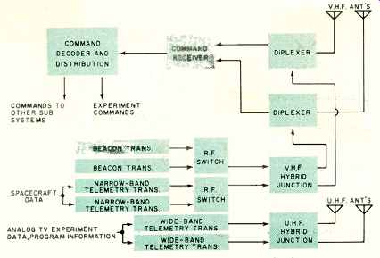
Fig. 4. Block diagram of the spacecraft communications system.
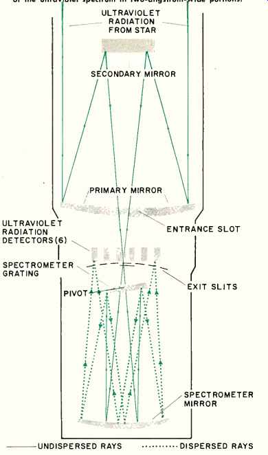
Fig. 5. This special telescope permits detailed observation of the ultraviolet
spectrum in two-angstrom-wide portions.
Spacecraft Electronics
As in all spacecraft, data transmission is vital. In the OAO, the spacecraft's command receiver (CRE) is part of the communications subsystem, a block diagram of which is shown in Fig. 4. R.f. signals are received in two channels, corresponding to the two v.h.f. slot antennas. The command signal sent to the CRE is a 148.260-mc. v.h.f. carrier, amplitude-modulated by the command modulation. Command modulation consists of the superposition of two subcarriers.
One subcarrier, known as the command-message modulation, is frequency-shift keyed (FSK) in accordance with the sequence of "1's" and "0's" in the message. The other, known as the message rate clock modulation, is a sinusoid at 1042 cps. The FSK subcarrier may be considered to consist of the alternate existence of two audio tones of equal amplitude, referred to as the "1" tone and the "0" tone. The command modulation is formally known as pulse-code modulation, non-return-to-zero, frequency-shift keyed, amplitude modulation or [PCM (NRZ) /FSK/AM]. Also part of the communications system are the radio-tracking beacon and the wide- and narrow-band telemetry transmitters. Operating at 136.440 mc., the beacon permits accurate orbital, tracking of the space craft. The narrow-band transmitter (NBT) is used for space craft telemetry data and for the echoing of commands for ground verification. In addition, although it is not a primary mode, the narrow-band transmitter can be used for experiment-data transmission. The output of the NBT is PCM (split-phase) phase-shift keyed (PSK ) and is sent at a rate of 1042 bits per second. The NBT, like the wide-band transmitter (WBT), is a completely solid-state unit. Each NBT consists of a crystal-controlled oscillator, a phase-shift keying modulator, an FM isolation and amplification stage, three stages of class-C amplification, a driver stage, a power output stage, a varactor doubler stage, RFI filter, and telemetry output circuitry. The WBT is capable of transmitting either analog or digital data. A video bandwidth of 62.5 kc. is used for analog information, with a total transmission bandwidth of 250 kc. Digital data can be transmitted as PCM /NRZ at a rate of 1042 bits per second in real time if it is received from experimenter's data-handling equipment, or at 50,000 bits per second from the data-storage unit or directly from the experiment. Power output of the WBT is eight watts over temperatures ranging between 0 and 130°F. The transmitting frequency is 400.550 mc.
Completing the spacecraft's electronic subsystems is the power supply subsystem. All power used on board the space craft is generated by the satellite's solar array, which is capable of generating approximately 1000 watts under the most favorable conditions with respect to incident sunlight.
The array employs p-n cell types of between 13% and 14% efficiency, and the total area devoted to solar cells is approximately 114 square feet. Each of the three OAO batteries consists of 22 series-connected, sealed nickel-cadmium cells of the 20-amp-hour size. Each battery is capable of supplying approximately 535 watt-hours of energy. Control of the battery during recharging is a critical operation and is performed by the battery-charge and sequence controller. A regulator-converter, which provides regulated d.c. outputs of several voltages, accepts unregulated 23 to 34 volts d.c. from either the array, if the spacecraft is in the sunlight, or the batteries if the spacecraft is occulted from the sun. Two multivibrator type power oscillators (master and slave) convert the un regulated d.c. inputs to square-wave pulses at 2 kc. The combined outputs of the master and slave oscillators are added in an autotransformer connection in the slave oscillator and a secondary connection in the master unit. The resulting output is full-wave rectified and filtered through diode rectifiers and LC section respectively. Voltage regulation is achieved by varying the phase angle between the master and slave oscillators. The a.c. demands of the inertia wheels as well as the gyros are supplied by an inverter.
All spacecraft electronics are mounted peripherally around the central structural cylinder which houses the main experiment package. By employing this structural arrangement, it is possible for the OAO to accommodate a variety of experiment packages without substantial changes to the basic spacecraft design. Hence, we find that the spacecraft is often referred to as one of the family of "streetcar" satellites, meaning that it accepts a variety of "passengers."
Experiment Packages
All current experiments are intended to explore regions of the electromagnetic spectrum that are essentially invisible to earthbound observers. A total of nine experiments will be included on board the first four OAO launches. A few of the key experiments will be discussed here. The initial OAO will have an experiment whose function will be to gather spectral energy distribution information on selected stars and nebulae in the ultraviolet range (100 to 4000 A). As a secondary function, the experiment will measure time-varying spectral-intensity data on particular stars. A total of seven observing instruments will be used to take these measurements. Four stellar photometers, each of which covers a bandwidth of approximately 1000 A, are used. In turn, each photometer is equipped with a programmable filter to further subdivide the coverage into 250-A bands. Also provided in the first OAO will be two scanning spectrometers. One covers the range of 1000 A to 2000 A while the other scans between 2000 A and 4000 A. A unique cycling device permits scanning the range in 100 steps, yielding intensity bandwidth of 10-A to 20-A wide. The final instrument is a nebular photometer capable of measuring the spectral intensity of star clouds as observed through five programmable filters, each covering 600-A bandwidths between 1500A and 3800A.
Another experiment is intended to measure the brightness of 50,000 main-sequence stars in the ultraviolet region between 1200 A and 2900 A. Called Project Celescope, the experiment contains four independent Schwarschild telescopes, each employing an imaging "uvicon" ( ultraviolet vidicon) system.
The bandwidths to be surveyed are 1200 A to 1600 A, 1300 A to 1600 A, 1600 A to 2900 A, and 2300 A to 2900 A. Be cause of its high rate of data output, this experiment will be done only during real-time contacts. A typical experiment routine would call for the warm-up of calibrator lamps in the five minutes just preceding ground contact. Three minutes of calibration will follow after con tact has been made. To use the Celescope, the uvicons are scanned in the digital-direct mode, and the first picture, including calibration information, is transmitted to the ground via the WBT.
Then, one or more standard Celescope data sequences are commanded. Each sequence includes a 60-second exposure and digital-direct scan for each camera.
A two-degree by two-degree region is mapped, with some overlap for ease in data interpretation.
Still another experiment will examine approximately 14,000 stars a year, at first producing a resolution of 2 A, which later will be upgraded to resolutions between .04 A and .05 A. Operation of this unique telescope is shown in Fig. 5. Ultraviolet light from a stellar source enters the telescope and is reflected off the primary 38-inch-diameter beryllium mirror onto a smaller quartz secondary mirror which converges the light onto the en trance slot leading to the spectrometer mirror. The spectrometer mirror directs the light to the spectrometer grating.
The grating is a ruled square which disperses the light and sends it back to the spectrometer mirror and thence to a series of exit slits in a grating. The light then passes through the 2-A slits in front of six photon-scintillation detectors. At appropriate times, the grating is synchronously rotated to facilitate illumination of the detectors by different portions of the spectrum, thereby permitting scanning of all the spectrum between 1000 and 4000 A.
Additional experiments will continue to survey the ultraviolet region while others will experiment in the x-ray and gamma-ray ranges.
The OAO program may prove to be one of the most interesting scientific projects yet conceived.