(source: Electronics World, Mar. 1966)
By RONALD L. IVES
Designed to be placed across the power line, this device will remove those annoying spikes that so often cause faulty readings on voltage-sensitive measuring equipment.
SENSITIVE electronic equipment, when operated from the power line, is subject to a variety of troubles resulting from electrical disturbances which come in over the line. These annoyances are most serious in industrialized areas, particularly when the power system is overloaded.
Oscilloscope studies of line waveforms show that the supposedly sinusoidal sup ply-voltage waveform can be disrupted by spikes of random frequency and amplitude, most of them being of quite short duration-usually only a few microseconds. Amplitudes of some of these spikes run to as much as five times peak line voltage.
Reduction of line spikes is easily accomplished by shunting a suitable capacitor across the line. Increasing the value of shunt capacitance will make the spike absorption more effective, but even a 10-uf. capacitor will not eliminate all spikes. A 100-uf. capacitor would be a happy solution, but such a capacitor, suitable for continuous operation across a 117-volt line, is not only a bit bulky and costly but also has a capacitive reactance of only about 26 ohms so that it will draw about 4.5 amperes from the line. This drain is likely to be much greater than that of the device to be protected. Although the shunt capacitor will usually improve the power factor so that all of the added drain will not show up on your electric bill, such a load increment is a bit excessive.
Line noise is also effectively reduced by use of four-terminal, ladder-type LC filters, many of which are available commercially at less than the cost of components (in small lots ). Representative of these is the J. W. Miller Co. "Cash Register Filter," a two-section device occupying 91 cubic inches (cased) and listing at $18.25. This unit, capable of handling any load up to 5 amperes at a line voltage up to 230 volts, is one of a family of effective line-noise filters.
At the current state of the art, another method of reducing line spikes and their undesired effects seems possible. This is a power analog of the well-known, but little-used, full-wave, self-adjusting noise limiter. A circuit of this with component values is shown in Fig. 1.
Operation is as follows. When the power is turned on, capacitor C3 charges from the line through the bridge rectifier, attaining equilibrium voltage, which is very nearly 1.414 times r.m.s. line voltage, in a few cycles. R1 is a peak current limiter, and R2 is a bleeder to pre vent C3 from charging to the peak value of the noise voltage. With no line noise, the limiter has an infinitesimal effect on line voltage and waveform characteristics.
Capacitor C1, shunted across the line, furnishes a high-impedance path for 60-cycle current, but a low-impedance short circuit for higher frequencies. It effectively shunts out high-frequency sinusoidal "riders" on the power line and de-peaks short-duration spikes. C2, at the output of the bridge rectifier, performs a similar function and is most desirable here, as electrolytic capacitors are not low-impedance paths at high frequencies.
Line spikes, of any polarity and du ration, pass from the line through the bridge rectifier to the storage capacitor C3. Here they are stored instantaneously and bled away slowly through R2.
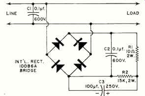
Fig. 1. The spike remover is basically a full-wave bridge rectifier circuit.
Performance
Tests of this line-spike absorber, in an industrial location where line noise is heavy, indicate that it is an effective performer. By its use, all electrical disturbances on the line having frequencies exceeding about 50 kc. and durations less than about 10 usec. were attenuated to values too small to measure (i.e., below 50 millivolts). Disturbances of lower frequency and/or of longer du ration were attenuated by 30 or more db.
Line-voltage surges, which initially appeared on the oscilloscope as "step functions," were de-peaked so that the line-voltage change occupied several cycles, substantially eliminating the "blop" formerly produced by such surges in sensitive receiving equipment.
Electrical placement of this line-spike absorber is quite important. When the noises originate exterior to the building, it is best placed at the service entrance so that it will attenuate the line noise before it has a chance to radiate from the interior wiring. If the noise is produced by a single source within the building, the spike absorber is best placed close ( electrically) to the noise source. When there are multiple noise sources, or if the equipment is portable, the spike absorber should be connected as close to the power input of the using device as possible.
Alternate Construction
Inspection of the spike-absorber circuit discloses that many pieces of electronic equipment contain salient parts of the absorber as power-supply components. If the equipment uses either full-wave bridge rectifiers or full-wave center-tap arrangements, the power supply already functions as a spike limiter. Improvement can usually be brought about by shunting the primary and secondary of the power transformer with small (0.02 to 0.1 uf.) paper, mica, or ceramic capacitors. A similar capacitor shunting the first filter capacitor, if it is electrolytic, will also help. Additional changes in the equipment are not likely to bring about further improvement.
In a number of instances, but not in all, marked reduction in line noise ( as well as pickup) was brought about by shunting the line on the load side of the device with a small capacitor, such as a 0.5-pf. (500-volt rating) unit.