
By WALKER SMITH /Technical Evaluations & Support Manager Micro Switch
(Div. of Honeywell, Inc.). The author is a graduate of the University of
Wisconsin and holds an E.E. degree. He served as a Lieutenant in the U.S.
Navy during World War II, assigned to the Bureau of Ordnance. At the time
proximity fuse ammunition was introduced to the fleet, he was assigned to
this project. He has been at Micro Switch since 1951.
Lighted devices indicate alarm or status reporting, signal command and response messages, provide verification, and pinpoint sources. Here is information on choosing the proper color, along with a check list showing factors to consider.
THE usefulness of lighted switching devices can best be demonstrated by an example. A typical check--which is routine practice at space telemetry stations--would find the Project Director at the control console in NASA Space Center, Houston. At the sane time, in our hypothetical case, his back-up man is seated in front of a similar console at Cape Kennedy. The Project Director presses three lighted push buttons. One is marked "Bahama", another " Azores ", the third "Canary ". All three stations on the Director's and back-up man's consoles appear yellow. Then, one-by-one, the button color changes to white. Next, "Bahama" turns green, " Azores" turns green, but "Canary" turns red. "Canary" has reported "no-go" for that station. All the Project Director sees is a display panel that he can push but, by doing so, he has asked the status of each station (yellow), while the message is verified (white) by the receiver. Reports on the same push button are then relayed in either red or green to answer his question. While this is not the most common use of lighted push buttons, it does show the need to pinpoint feedback messages from a massive array of functions.
In contrast, when an operator sees or hears feedback sights and sounds directly from the work he is controlling, lighted devices are usually unnecessary. Once the switch is actuated, the operator can see, or hear, the results.
Frequently, however, operators are physically separated from the work area, or are responsible for the control of numerous functions (often unrelated). When this is the ease, the operator needs help in the following problem areas:
1. Has initiation, cycling, or completion of work occurred?
2. Are there too many sights or sounds being communicated to the operator at one time?
3. How can the operator communicate with another operator or master station?
4. How are warnings, dangerous conditions, or feedback messages conveyed?
In general, lighted devices can provide:
1. verification, 2. pinpointed sources or distinct communications from a mass without confusion, 3, command or response messages received and sent in a telegraphic form of words or colors, and 4, alarm or status reporting.
By definition, lighted devices can be simple indicating lights or, when coupled with a switch or other control, an integrally lighted push button, push-pull, selector, selector-push, or an alarm annunciator. The latter is often coupled with an audible alarm and reset mechanism.
Lighted push buttons and indicating lights range in size from the diameter of a 50-cent piece, with single-lamp circuit and heavy-duty pushbutton electrical ratings, down to push buttons containing four lamps in a 3/4" x 3/4" space which can switch 5 amps resistive load at 120 volts a.c.
================
LIGHTED DEVICES CHECK LIST
This application check list outlines important factors in the selection of lighted devices.
Need---Is the ambient light bright enough to allow the operator to perform the other tasks which are not lighted? Is the ambient light so bright that it overpowers the lamp's output?
Ambient Light--Is the ambient light bright enough to allow the operator to perform the other tasks which are not lighted? Is the ambient light so bright that it overpowers the lamp's output?
Lighted Device---Does the lighted device provide sufficient light output for contrast between "on" and "off' states? Would an alternative lamp help? Would a change in the display color help? Would a change in the ambient light level help?
Display----Is the display achieved by projected or transmitted light? Is any legending required? Is sufficient legending space available on the device?
Lamps---What is the lamp's application voltage in relation to its design voltage? How does this affect the lamp's life? Brightness? Wattage? Heat? Will the lamp experience vibration and shock? Will the filament be allowed to cool between operations? Is there a lamp "on-time" restriction due to excessive heat to the button? Will the number of lamps being energized exceed the maximum wattage (heat-distortion point) of the device?
Critical Use--Is it recommended that the lamp's operation not be the sole source of information regarding human safety? Redundant lamps, secondary annunciation, timed lamp replacement, and other factors in the application must be considered for concurrent use.
Switch Requirements--See "Check List for Ordering Switches" in the article "Snap-Action Switches" in this Special Section.
================
The size of the indicator is usually related to: size of the lamp, sealing of the unit, whether service voltage devices (such as transformers or resistors) are incorporated, and switches for controlling circuits. The features required spell out the device use areas.
For example, a push button on a computer does not require the degree of sealing necessary on an industrial machine. In an industrial application, typical voltages are 120, 240, 480, and 600 volts a.c.; oils, coolants, and lubricants are apt to disrupt the lamp or control circuits if not sealed; and excessive force in striking the push button may be a habit. This is quite a contrast to what the pretty young thing wants when she is changing the encoding for a computer.
Miniature Lamps
Lamps used in indicators and controls range in size from the G-3 1/2 down to T-1--or 7/16" in diameter down to 1 /8" in diameter. Lamp size is usually proportionally related to its light output or brightness, for a comparable life expectancy. This can be a problem in applications which require a small device (small lamps) but the ambient light is so high that it overpowers the lamp's "on-off" contrast. Conversely, a dimly lit room with brilliant indicators can, over a long period of time, produce eyestrain from glare.
The range of lamp voltages is usually wider as the lamp size increases. As the bulb size increases, the lamp can effectively dissipate more heat for long-life operation at higher voltages.
Incandescent lamps are heat producers because the tungsten filament burns at between 2000-3000° K. Heat can distort color-coded plastic lenses if the lamp is driven above its design or rating and the heat produced exceeds the indicator's maximum temperature limit. This problem is outweighed by the efficiency of the lamp in producing high light output for its relatively small size.
When light output of a subminiature incandescent lamp is charted, the following relative energies are found when the lamp is burning at approximately 2750° K.
Relative energy: 5-20 20-35 35-50 50-60 60-75
Color: Blue Green Yellow Amber Red
As the lamp generates light closer to red (and infrared) its relative energy level increases over other spectral colors. Most lighted push buttons and indicators are offered in above five colors (and white) since they provide the clearest contrast between the different colors and the "on-off" display of the unit.
Should a different color be used, such as blue-green (aquamarine), it would be difficult to pinpoint which display was green, which blue, and which aqua. As shown above, blue-colored lamps, having the lowest energy level, will be the first color washed out by high ambient light levels. Red, on the other hand, will maintain greater contrast between "on-off" states under higher ambient light conditions.
Here are six helpful hints for obtaining the greatest lamp life:
1. Voltage surges or application of voltages above the lamp's rating can shorten life. Voltage held slightly below the lamp's rated voltage decreases the light output slightly but increases lamp life considerably.
2. Continuously operated lamps last longer than lamps that are cycled on and off at a slow rate, allowing the filament to cool. Some applications provide a trickle current flow during the lamp's normally "off" state to maintain filament heat. In flasher operations, where the lamp is not allowed to cool, its life approaches that of continuous use.
3. Lamp life is generally longer when applied to surfaces that do not vibrate or receive shock. In most lighted devices care has been taken to assure a free-moving actuator and a stable lamp position. Where vibration or shock is anticipated in the application, a change to a lower lamp-design voltage is desirable since the tungsten filament is thicker and shorter on the lower voltage lamps.
For example, a 6-volt lamp can withstand more vibration than a like configuration 28-volt lamp. With severe vibration, the use of neon lamps (without filaments), is recommended. However, neon light output is very low.
4. When operating lamps with resistors in the circuit, lamp life is shorter than in a comparable transformer circuit application because the lamp's voltage increases as the filament material used in the lamp evaporates.
5. As the applied voltage is decreased, light output and filament heat decrease. This results in greatly increased lamp life. Conversely, as voltage is increased beyond the design voltage, light output and filament heat increase while lamp life decreases significantly. See Figs. 1 and 2.
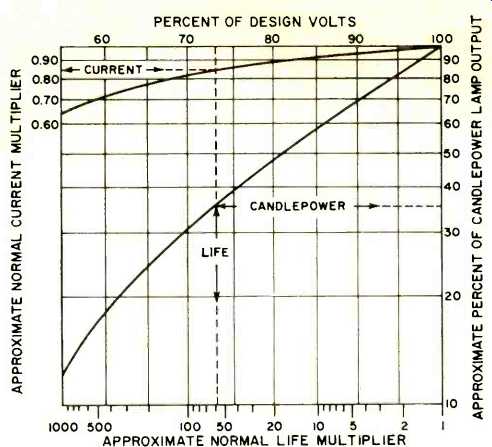
Fig. 1. Effects of lamp operation below its normal voltage.
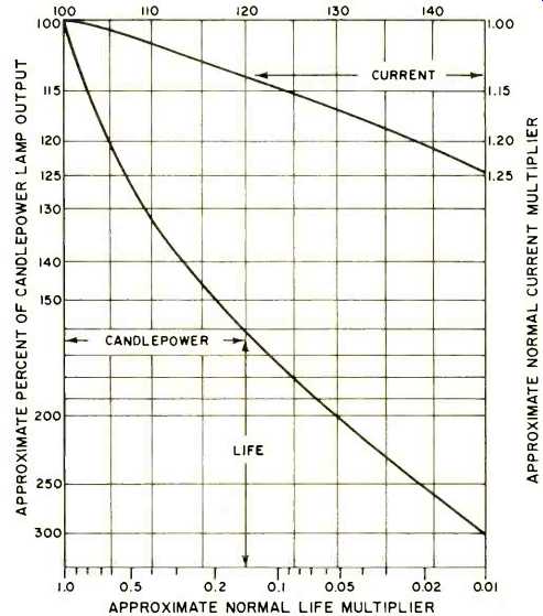
Fig. 2. Effects of lamp operation above its normal voltage.
6. At reduced lamp voltage, few colors are suitable.
Blue and green displays, for example, have problems with brightness fall-off because of the decreased output from tungsten filament lamps and the inherent "dimness" of these colors. Amber and yellow displays, operated at reduced voltage, can appear as one color when they are separated on the panel. White and yellow also look quite similar at reduced values of voltage.
Color Display
The color display of an indicator's light is available with either transmitted or projected color. Transmitted color means that the lamp itself is clear and its light is transmitted through a colored display screen to achieve the desired results. For example, when incident light is reflected from a green display screen, it appears dark green in the unlighted state and brilliant green when lighted. The contrast between the lighted and unlighted state is significant because of the low reflectance of the display screen material (Fig. 3) .
Projected color indicates a colored lamp or involves the use of a colored filter. The color of the lamp, or filtered light, is projected against a white screen which causes the screen to appear in color. A white display screen reflects more light than a colored screen when the lamp is not energized. In high ambient light, the reflectance of the white display screen could be intense enough to wash out all of the color from the indicator's lamp (Fig. 4) .
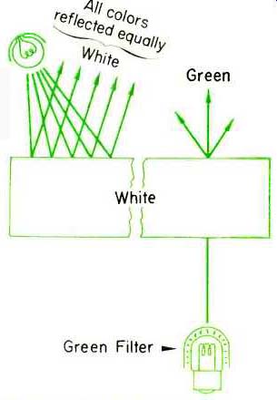
Fig. 4. Projected color using a white display screen.
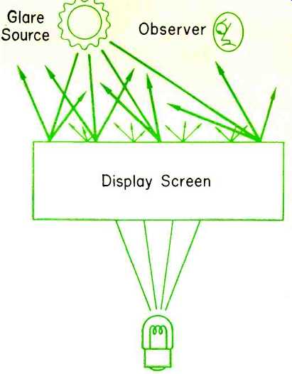
Fig. 5. High glare source, such as sun, reduces contrast.
For these reasons, the use of projected colors is not recommended at high ambient light levels because of the greatly reduced contrast between the lighted and unlighted states.
Lighted displays subjected to sunlight (approximately 5000 to 19,000 footcandles) lose desirable display contrast between the "on" and "off" states. Both transmitted and projected colors are washed out by this extremely high ambient light. Screens or covers that shield the panel from the sun can be used to increase contrast between the indicator's lighted and unlighted states (Fig. 5). Even indoors, both transmitted and projected colors can be washed out when the angle of the display screen reflects glare to the operator. A minor change in panel angle or diffusion at the glare source reduces this problem.
Panels Containing Lighted Devices
Since panels may be responsible for operator fatigue or cause color confusion, a few simple precautions will help minimize these conditions. When smooth or highly polished panels mirror and reflect glare, a small change in the panel angle will often eliminate much of the trouble. Shielding between the light source and the panel may also be effective in eliminating glare. Textured or grained panel surfaces will also help in reducing reflected light.
A brilliant yellow panel can alter the apparent hues of any colored display and possibly cause color confusion.
Vivid colors on the panel can cause operator fatigue and for this reason should be avoided. Where high ambient light reduces contrast, a darker panel color may be used to improve "on-off" recognition.
For general use, the panel should be uniformly illuminated with diffused light. Light level should be high enough to permit the operator to work on non-lighted objects, but at the same time low enough to permit easy recognition of the device's lighted state.
Available Lighted Devices
When an unlighted push button and a separate indicator are used on a panel to actuate and indicate the same function, substantial savings are possible if the devices are combined in a single lighted push button. In these devices, the lamp circuits are usually independent of the control circuit.
Push buttons used in the electronics industry are generally equipped with snap-action switches for low operating force and to minimize the plunger travel needed for actuating the switch. These push buttons can be equipped for momentary actuation (push to actuate, spring release) , alternate action (push to actuate and push to release) , hold-in coil (push to actuate, held actuated by coil, release by deenergization of coil) , remote pull-in and release (may be actuated by pushing or actuating coil which remains actuated until coil is released) , alternate-action, electric trip (push to actuate, push to release, or push to actuate, energize coil to release) . Several lighted push button lines also contain mechanical interlocking to prevent operation of two buttons at the same time, or to insure that only one button is held actuated at a time. Each push button can accept from one to four s.p.d.t. switches, in combination with one to four lamps.
Push buttons in the industrial control field are, of necessity, more rugged and require a longer stroke to actuate a circuit and are sealed to prevent contaminants from entering the electrical contact areas. Usually these devices incorporate transformers, resistors, or other service voltage devices. These units do not accept integral hold-in, remote control, or release coils.
Some industrial control units are available as selectors and selector-push units with four lamps and four transformers in single units. These units reduce panel cost where the operator is separated from the work he is performing. The electrical loading of the contacts is usually heavy duty (high in-rush) or d.c. inductive, as well as resistive and instrumentation loads.
These mechanisms let the panel designer obtain a variety of switching objectives in minimum panel space.
(source: Electronics World, Oct. 1967)
Also see: Precision Rotary Commutating Switches