By PETER WAZNYS / Senior Engineer, Collectron Corp.
IN contrast with detented or snap-action switches, the precision rotary commutating switch provides a smooth accurate transition between conducting and non-conducting surfaces. Also, these switches are designed to be rotated at fairly high speeds by means of a drive motor.
Standard detented rotary switches divide 360° or less into some equal multiple of "on-off" time. The rotary precision switch, on the other hand, can provide a variety of switching functions of unequal "on" time, if necessary, in accordance with some prearranged code. Complex logic switching sequences can be obtained by additional wipers and conductive rings.
Two basic mechanical configurations associated with precision rotary switches along with a photo of a typical switch are shown below. Both drum- and disc-type construction are used. Precious metals-gold, platinum, silver, and their alloys-are used for wiper and contact ring materials to reduce oxidation and contact resistance.
This type of switch, normally operating at low voltages and currents (below 500 milliamperes), is not considered a power-switching device but rather an information-transmitter switch to external circuitry. The amount of information that can be delivered is limited by the physical size of the switch itself. Naturally, the larger the switch diameter, the more "on-off" possibilities that are available.
Lack of detented positions in the precision rotary switch precludes manual operation. In most applications of this type of switch, electrical or mechanical drives, such as a gear train or servo motor, provide the necessary input. The switching output can be either directly or indirectly coupled to the switching circuit. Switch operations which perform within the electrical limitations of the switch can be directly coupled. Operations which require auxiliary assistance, such as with relays, are classified as indirectly coupled.
Switch versatility can best be illustrated by typical applications, which include tachometers, simulated potentiometers, incremental encoders, operation sequence controls, and machine-tool programmers.
A precision multi-speed tachometer can be developed by relating pulse frequency ( "on-off") to the speed of shaft rotation in r /min. The smooth shaft transitions inherent in this type of switch allow high-speed switching without pulsating torque, snap-over, and wiper bounce. Switches of this type have exceeded 400,000,000 revolutions, at 3600 r /min, and are now being tested at 16,000 r /min.
Shunting conducting segments with external resistors together with a make-before-break wiper will simulate a stepped potentiometer output.
A uniform "on-off" switching sequence permits the switch to be used as an incremental encoder. Through appropriate mechanical drives and code pattern, the switch can divide multiples of revolutions or parts of revolutions into accurate finite values. The signal can then be sent to a pulse accumulator for a visual digital readout.
It is a delicate operation to adjust and maintain a consistent switch cycle involving time delays. A multi-gang switch with a preselected code pattern can be used in relay circuits which must operate in some desired cyclic sequence. The precision rotary switch provides not only the proper sequence but also the added versatility of changing the switching speed by simply changing the drive motor speed.
An extension of the above technique could be made in simple automatic machining of large quantities of a particular part, for example, in drilling holes at various angular positions in a flat disc. One pole would locate the turntable while the second would signal the drill spindle.
Inquiries to manufacturers of these switches should contain as many design parameters as possible. Include current, voltage, load type, contact resistance, noise allowed, switching code, number of poles, insulation resistance, size, speed, torque, life, and ambient conditions.
Precision rotary switches are usually manufactured to particular customer specifications. Depending upon quantity, switch materials, accuracy, and number of circuits required, the relative cost may vary from 3 to 10 times that of detented switches. Relative cost depends upon the parameters established by the design checklist. For military applications, precision rotary switches should meet the test requirements of MIL-Std.-202, MIL-E-5470, and MIL-E-5272.
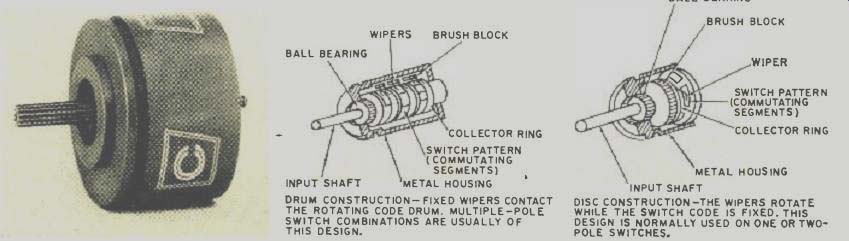
above: DRUM CONSTRUCTION FIXED WIPERS CONTACT THE ROTATING CODE DRUM. MULTIPLE-POLE
SWITCH COMBINATIONS ARE USUALLY OF THIS DESIGN.
DISC CONSTRUCTION--THE WIPERS ROTATE WHILE THE SWITCH CODE IS FIXED. THIS DESIGN IS NORMALLY USED ON ONE- OR TWO-POLE SWITCHES
(source: Electronics World, Oct. 1967)
Also see: Slide Switches and their Ganged Arrays