
By HARRY H. MEYER / Director of Engineering, Micro Switch (Div. of Honeywell)
[The author is a graduate of M.I.T. and a 15-year veteran of the
Honeywell organization, having served as Project Manager on the F-104 contract
of the Aeronautical Division. In 1963 he became Chief Engineer of the Residential
Division in Minneapolis and in 1966 he was named to his present post. He
is a member of the American Society of Mechanical Engineers (ASME) and of
the American Society of Heating, Refrigeration and Air-conditioning Engineers
(ASHRAE).]
These switches are characterized by positive actuation with small mechanical pressure along with small size and high electrical capacity. Included are answers to the most important questions asked concerning the proper choice of these switches as well as a checklist for ordering switches of all types.
THE five principal features of precision snap-action switches are: actuation with minute mechanical motions and forces; small size; long life; uniform travel and force characteristics; and high electrical capacity for their size. Various actuator devices, integral or accessory, are available for these switches. These provide easy adaptation to rotary or linear mechanical drive and manual operation as well as meeting the requirements of diverse uses ill electronics, major appliances, machine tools, and aircraft.
A wide choice of sizes is available, without sacrificing good load-carrying ability. Units as small as 0.035 cubic inch will reliably switch 28-volt d.c. inductive loads of 4 amperes or 125/250-volt a.c. loads of as much as 7 amperes.
Other snap-action switches of somewhat greater size, yet still less than 1.3 cubic inches, will control 20-ampere, 480-volt a.c. loads.
These switches can directly control: motors and other work-performing equipment; read-out devices for operator instructions or recording; and protective interlocking or detection circuitry. Their small size permits use in normally inaccessible areas. Actuation or release of the contacts occurs within a few thousandths of an inch of plunger travel which helps prolong mechanical life.
Snap-action switches must provide reliable operation for extended periods of time. In use, they serve as a substitute for human hands and eyes in controlling electrical action.
To simplify the selection of precision snap-action switches and to obtain the best service results, the following check list is broken clown into five areas: mechanical requirements, electrical requirements, reliability, environment, and installation factors.
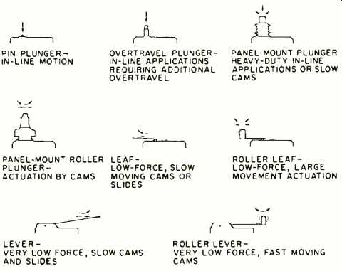
Fig. 1. Some of the actuators that are available for the basic snap-action
switch, along with their applications.
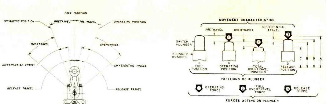
Fig. 2. Illustration of terms that are employed in describing rotary actuation
(left) and in-line plunger actuation.
Mechanical Requirements
How will the switch be operated? Linear, rotary, and multi-direction and variable motion can actuate snap-action switches. The wide variety of operating mechanisms includes push-plungers, roller-plungers, levers, roller levers, one-way roller levers, flexible wires, and coil wands (Fig. 1) . What will be the rate of motion for actuation of the switch? Micro-motion, intermediate motion, and impact motion can be handled by snap-action switches. Protective devices are available for impact actuation. An alternative switch location, or an alternative means of actuation to reduce impact motion, is desirable for optimum switch life.
What will be the frequency of switch operation? Switches can be operated from low to high frequency. In general, switch life is affected only when heavy electrical loads are driven at a high cycling rate which generates excessive internal heat. Most snap-action switches can handle their rated loads up to 150 operations per minute. As the electrical load is decreased, the frequency of operation can be increased-successfully-on the order of 1800 cycles per minute.
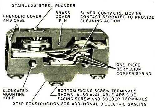
Internal construction details of basic snap-action switch.
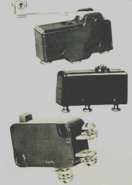
Several typical examples of the basic switch. It is possible to
use this mechanism with many different types of actuators including push
button, toggle, and rotary (using cam) types.
What operating force is available? Is a broken thread being detected or is actuation accomplished by an internal flywheel cam? Switches with operating torques as low as 4 gm /in, maximum, are available. In heavy industrial applications, operating force is usually abundant, whereas in servomechanisms the operating force is low.
What will be the length of operating travel? Excess linear or angular travel of the switch actuator can damage or greatly reduce the mechanical life of a switch. For snap-action switches, plunger pre-travel, overtravel, and differential travel positions or length are specified. Plunger travel beyond the point of actuation is overtravel. Travel from the point of actuation to the point where snap-action release occurs is differential travel. Optimum life is obtained when operating travel does not reach the full overtravel limit of the switch and permits full release of the plunger between cycles (Fig. q). Electrical Requirements
What circuitry is required? Single-pole, single-throw in normally closed or normally open configuration, single-pole, double-throw, two-circuit, double-break, or multiples thereof are available contact arrangements. Double-break switches make and break a circuit at two points, which effectively increases the contact break distance. Double-break switches allow interruption of greater d.c. and a.c. inductive loads than is possible with single-break switches.
What contact action is required? Self-returning momentary, maintained, make-before-break, and pulse action are available. Momentary switches actuate when the plunger is depressed and release when force is absent. Maintained contact switches require one operation for actuation and a second operation to reset the contacts. This type of mechanism can be used in protective interlocking to open a circuit when a fault occurs. When the fault is corrected, the contacts are reset. Make-before-break versions provide momentary overlapping when switching from one position to another and is useful where circuits must be switched with no interruption. Pulse action provides a single electrical pulse each time the actuator is depressed, but not when released. When operated by a single lobed cans, the switch provides a single pulse per revolution.
What are the electrical parameters of the load? Specify voltage and whether alternating or direct current will be passing through the switch. If a.c., specify the frequency.
Specify the nature of the load: resistive, as a heater: inductive, as a coil; reactive, as a motor; or tungsten filament, as a lamp. Where applicable, specify in-rush and steady-state current requirements as well as power factor.
Keeping electrical loads within the published capability of the switch is of primary importance for long, reliable life. Snap-action switches are frequently selected on the basis of continuous current ratings of motors and solenoids without proper consideration being given to in-rush capacity. Only certain types of switches are rated by UL for control of tungsten-filament lamps.
Large amounts of alternating-current power can be reliably controlled even with small-size snap-action switches.
At rated loads, difficulty with prompt interruption of a.c. loads is unknown under ground-level operating conditions.
Temperature rise is seldom important, except when caused by heating of the arc on maintained high-speed cycling of heavy loads. For low-energy circuits operating in the millivolt, milliampere range, special contact materials and designs are used to minimize and stabilize contact resistance for extended and reliable life.
Single-break snap-action switches handling direct-current loads, especially inductive loads, should be equipped with contact protective diodes or capacitor /resistor networks to reduce arcing and the transfer of contact materials during circuit break. Because of the small contact separation in snap-action switches, unprotected contacts handling a d.c. inductive load may not be able to extinguish the break arc that is produced.
Reliability
What constitutes failure of the switch? Reliability of switch operation depends primarily on mechanical and environmental factors, yet electrical loads can have a marked effect on switch life. Operating accuracy is one measure of reliability, life expectancy is another.
What is the permissible deviation from nominal point of actuation? As the load increases, small contact welds can occur. To compensate for this, the switch requires increased operating motion and force. Under small electrical load, usually no greater than 0.1 A, maximum repeatability can be obtained.
What switch life is expected for the application? The mechanical life to be expected from a snap-action switch depends on the type of switch and whether it is driven to the limit of its stroke at each operation. In general, mechanical life catalogue data is on the order of 10 to 20 million operations (based on full stroke) . Under full rated electrical loads, contacts usually reach full useful life in less than the probable mechanical life of the spring system. In many cases, however, probable contact life up to 10 million operations may be expected. At low loads with less than full plunger travel, test switches and switches in actual applications have operated more than 150 million times.
If failure to make or break a circuit could be disastrous in critical applications, the switch should be replaced regularly as a matter of routine. The replacement cost is only of fraction of the cost of down time.
Environment
What is the ambient temperature? Standard snap-action switches perform satisfactorily in ambient temperatures from approximately-65° up to 180° F. Ceramic-metal variations are available in the market for operation down to-321° and up to +1000° F.
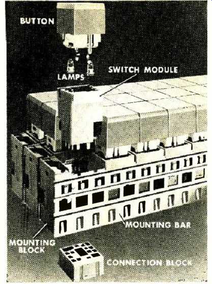
A large number of switch modules may be combined to form customized
lighted or unlighted panels and keyboards.
What is the surrounding environment? Excessive humidity, oil vapor, liquid splash, and immersion are detrimental to the switch, unless it is equipped with a protective enclosure which prevents the entrance of adverse environmental conditions into the contacts of the switch. Moisture causes electrical breakdown in a switch. Oil may be carbonized by arcing and, in this form, can lead to non-contact conditions or excessive leakage currents.
Will the switch be exposed to weather? Most snap-action switches can be protected by enclosures so that they can be used outdoors. Since a movable member is required for switch actuation, additional protection should be provided for the actuator against severe ice accumulations.
Will the switch be exposed to corrosive atmospheres?, Salt fog, sulphur vapors, and acid fumes are some of the airborne contaminants that can affect unsealed switches.
Is the surrounding environment gritty or dusty? Minute dust particles can be drawn into the contact chamber of unsealed snap-action switches through changing air pressures. Dust particles can contaminate contacts and prevent reliable contact operation or cause complete failure. These particles can also contribute to mechanical failures at bearing and pivot points. Enclosures are available.
Are flammable gases or combustible dusts present? Snap-action switches can be used in flammable gas or combustible dust locations when the switch is housed in an enclosure of adequate strength and it has sufficient flame path or is of flame arrest construction. In flammable gases, the switch is allowed to "breathe" clue to atmospheric pressure changes and the switch can withstand internal explosions. Construction features prevent explosion from triggering the surrounding gas. Also, the enclosure is not allowed to develop sufficient heat or char or cause combustion of the dust. When using snap-action switches in hazardous locations, specify the substance (gas or dust) surrounding the switch.
Will the switch be subjected to acceleration, vibration, or shock? Snap-action switches will resist false operation due to acceleration, vibration, or shock when the contact force is optimized (full overtravel and full release) . Operation of the switch near the point of actuation or release, when subjected to these external forces, may cause momentary separation of contacts or false snap-over. Satisfactory performance varies with the contact break distance, for example. 0.008-in break distance withstands up to 40 g; 0A.020 in up to 80 g; 0.070 up to 200 g. Locating the switch so that the snap-over spring is parallel to the direction of force increases the ability of the switch to withstand these external forces.
Will the switch be subjected to physical abuse or negligence? Snap-action switches should be protected with rugged enclosures to assure reliability of operation, long life, and live voltage protection for the operator in case the switch is subjected to physical abuse or negligence.
Will the switch be subjected to decreased air pressure or hare to operate in a vacuum? Snap-action switches generally operate satisfactorily between sea level and pressures corresponding to 25,000 feet altitude. As decompression progresses, switch arc time increases, momentary flashover between terminals results, and dielectric problems arise in unsealed switches.
Snap-action switches which are hermetically sealed and which incorporate insulated lead wires can provide the best performance during and after pressure reduction. Life duration of hermetically sealed switches is derated to reflect maintenance of the seal.
Installation Factors
What termination will be required on the switch? Screw terminal, quick-connect, solder terminals, and wire-clamp type terminals are available. When soldering terminals on snap-action switches, care should be exercised to avoid excessive flux and soldering temperatures that exceed 370° F for longer than 10 seconds. Flux can create an insulating filet on contacts and the movement of the flux on the terminals increases with higher soldering temperatures. Higher soldering temperatures expose the switch to a high-temperature shock so that such temperatures should be avoided.
Is switch size important in the application? Snap-action switches vary in size, depending on the electrical capacity required, whether or not an enclosure is needed, the style of the actuator, and the space available in the application.
Will a conduit connection be required? Sealed enclosures require adequate conduit sealing to maintain the integrity of the enclosure. Condensation or oil seepage can enter the switch unless it is adequately protected by its enclosure and, in addition, is well sealed at the conduit entrance.
Will the switch be at a serviceable location? In order to minimize the expense of unexpected shutdowns, machines and systems should be designed so that the control units which are subject to wear or damage are easily accessible for repair or replacement. Plug-in enclosure versions are readily available in order to reduce the down time by eliminating the need to rewire the switch.
Ganging Snap-action Switches
In many applications basic switches are ganged or stacked to provide the necessary control functions. .k gang of switches can be two or more units mounted together. This provides it multi-pole switch device which very often is operated by a single actuator. Ganged switches are usually more practical than a multi-pole single switch because the component switches are less costly and provide the designer with a greater choice of termination, actuating device, and circuitry.
Available are split-contact, double-throw, and two-pole double-throw switches in a single housing. When a designer's steeds exceed these types of circuitry, two or more individual switches are used.
Snap-action switches can be ganged successfully because they are built to small gradations of movements amt the "snap," or transfer of contacts, repeats lone cycle to the next) , within a usual maximum variation of +0.002 to -0.003 inch.
What makes such switches ideally suited for ganging is the variety of sizes available to the designer. They are offered in a size range from basic, to miniature, subminiature, and sub-subminiature.
In placing one switch next to another (and as many as 24 switches have been ganged), the design engineer has to be sure that the tolerances of the actuator and switch travel specifications are compatible. Each switch should be mounted individually so it can be moved towards or away from the actuator to obtain the correct timing of operation with relation to the next switch. However, the usual method of ganging switches is to mount them on the same rods or screws so that they are not adjustable on an individual basis.
When switches are ganged, multi-circuit operation is required at a specific time. Without individual switch adjustment, it then becomes necessary to adjust the actuator of the switches.
Ganged switches are very often actuated by means of cants fixed to rotating shafts in such devices as timers, which are mostly motor driven, or selector switches which are manually operated. Timers and programmers are products in which ganging of switches is a basic part of the product design.
Ganged switches are also used in devices where the actuating means are a pivoted lever that provides nearly simultaneous operation all the way to make-before-break type sequencing. Multi-pole push button, pressure and temperature-sensitive switches, electrical coil-actuated devices, and many other electromechanical designs also employ this type of actuation.
Cams and levers, to a great degree, have built-in adjustments to insure that a switch and each subsequent switch operates at the precise time required by the circuit. One lever could operate as many as six switches in some devices.
The need to gang switches is not confined to a limited number of products. The computer, business machine, and the vending machine all use the ganging technique.
Ganging of switches is economical in the sense that the application does not require multi-operators and mechanisms just to actuate one switch. This aids in reducing the size of the control package.
Since precision snap-action switches are comparatively inexpensive--usually under $1.00 per switch--the ganging of switches is a low-cost method of multi-circuit sequencing.
CHECK LIST FOR ORDERING SWITCHES:
Switches are offered in a variety of forms, sizes, and electrical ratings to fit the majority of application requirements. This check list is provided as a reminder of the areas to be considered when specifying in simple applications. However, in exotic installations, further information may be required in order to select the correct switch for reliable performance and maximum switch life.
ELECTRICAL LOAD
- Voltage (a.c. or d.c., specify frequency)
- Amperage
- Type (resistive, motor, lamp, inductive)
- Electrical life required
SWITCH ACTION
- Type (snap-action, reed, double-break, mercury)
- Action (momentary, pulse, maintained)
STANDARDS AND SPECIFICATIONS
- MIL-Spec (specify number and sections)
- UL, CSA
- Other
MECHANICAL DATA
- Operating force
- Length of operating travel (pre-travel, overtravel, differential travel)
- Rate of motion
- Frequency of operation
- Mechanical life required
ENVIRONMENT
- Temperature
- Grit or dust
- Humidity
- Oil or sulphur
- Hazardous gas or dust (specify)
- Acceleration, vibration, or shock
- Physical abuse or operator sabotage
INSTALLATION FACTORS
- Conduit connection
- Termination
- Field adjustability
- Switch size
- Enclosure or sealing
- Serviceable location
(source: Electronics World, Oct. 1967)
Also see: Open-Frame Rotary Switches