
By JAMES BAILEY/ Director of Research & Development Switchcraft, Inc.
[The author is a veteran of 22 years in the field of electrical development and engineering and is today recognized as one of the industry's authorities on the design and development of electromechanical switching devices. He joined the firm about 12 years ago as chief engineer and assumed his present position in 1962. Before coming to Switchcraft, he served as a design engineer on such varied products as hearing aids, wire and tape recorders, d.c. motors, and silver alkaline batteries used in guided missiles.]
These leaf-spring switches are used because of their economy, simplicity, reliability of performance, and ease of maintenance. Items to consider in choosing the proper switch are covered.
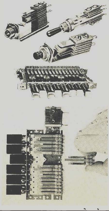
Fig. 1. Stack switches may be operated by push buttons, handles,
or phone plugs. They are also available in ganged arrays.
ALMOST indifferent to the more sophisticated advances in switching, the stack switch remains one of the most useful, versatile switching devices available to the circuit design engineer because of its simplicity, reliability of performance, and ease of maintenance.
Why use a stack switch? Because it may cost less per switch configuration than most other products. When properly engineered into the end product, it will provide very long life. If it has to be serviced, the technician can readily understand the mechanism and locate the trouble. Finally, its versatility is unmatched in meeting special circuit requirements in the initial design or when additional circuitry must he accommodated at a later date clue to revisions in the end product.
With all its advantages, the stack switch is not recommended for high shock, anti-capacitance, high vibration, or temperature extremes.
Stack switches are included as a stub-assembly in many switching devices, such as lever keys, relays, push-button switches, and phone jacks, as shown in Fig. 1. However, many are mounted separately and actuated by various means for machine tool control, indexing, data input and retrieval, and sequence control. No matter what the application, the primary considerations in specifying a stack switch are: 1. the switching configuration desired, 2. the method of actuation to be used, 3. electrical circuit considerations, 4. environmental conditions, and 5. cost.
A stack switch consists of an actuator spring, contact springs, insulating spacers, insulating tubing, and mounting screws. (Refer to Fig. 2.) Switching Configurations Basic contact forms A through F (Fig. 3) may be specified on stack switches. However, caution must be exercised when specifying the total number of springs used in each stack.
Attempts to use too many springs per pile-up can result in stack sway, loosened stacks, and loss of adjustment due to accumulative spacer cold flow and excessive operating forces.
Also, the total number of configurations per stack will be governed by the contact size and insulators required to obtain the necessary contact clearances for proper adjustment and operation. Where two or more stack positions are available, it is always advisable to distribute the switching configurations as evenly as possible to avoid excessively high stacks.
Ideally, each moving spring will be tensioned to result in 30 to 100 grams' contact pressure. If other design factors of the switch dictate lighter contact pressure, say 10 to 20 grams, then gold or palladium contacts may be specified.
For higher contact pressures, such as for an example in the hundreds of grams or more, tungsten contacts are recommended.
An example of the versatility of stack switches is their adaptability to special contact forms or sequential operation. Late or preliminary makes or breaks may be specified for various circuit control requirements. However, some consideration must be given to the position of these special configurations in the spring stack. For instance, preliminary make or break contacts should be placed at the bottom position of the stack. Late breaks should generally be positioned at the top of the stack in order that adequate contact pressure may be maintained throughout the travel of the moving spring.
Method of Actuation
While considerable freedom as to the method of actuation is an inherent feature of stack switches, certain dimensional and force characteristics must be coordinated in the actuator design. First, the actuator spring is normally part of the switching or contact configuration, hence the actuator is usually a suitable insulator material such as fiber, plastic, or phenolic. The stack assembly requires a minimum of amount of travel to properly actuate all contact springs since too much travel will induce unnecessary spring fatigue and cause excessive contact wear. For an ideal switch, the user should design the actuator to provide an 0.010" to 0.020" contact follow after closure and a contact gap of 0.020" to 0.030" between break contacts after the switch has fully operated. See Fig. 4.
Another consideration is the speed of operation. Excessively slow operate or release timing could seriously affect contact life, especially where inductive loads are involved.
Slow operate or release time is generally acceptable for a.c. circuits, but quick release is desirable for d.c. switching to achieve maximum contact life.
Mechanical switch life is practically impossible to specify without complete knowledge of all parameters involved. A good stack switch, suitably mounted and actuated, should provide 500,000 or more operations. However, this figure could be far above or below measured life for any particular application. Maximum life may be obtained by close adherence to switch travel requirements and by designing the actuator for a minimum amount of wear on the actuator spring.
Three common spring materials for stack switches are: nickel silver, phosphor bronze, and beryllium) copper. Phosphor bronze is standard for many assemblies, however nickel silver has improved strength and flexure characteristics and will he furnished on quality units. Beryllium copper should be specified where exceedingly long mechanical life is required. This material is often used where severe spring forms are needed as it is highly ductile and can be tempered after forming.
Electrical Circuit Considerations
Stack switches are generally designed to accommodate switching currents from low-level dry circuits up to 5 amps, 500 watts. Contact resistance becomes a major factor in low-level circuits due to organic materials or condensates and oxides that may collect or form on the contact surfaces.
Gold alloys, in combination with platinum and silver, and sufficient contact forces usually minimize oxidation and other contaminant problems.
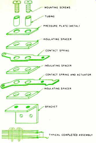
Fig. 2. An exploded view of simple stack assembly is shown here along with
a more complex completed stack switch unit.
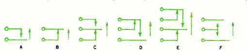
Fig. 3. The basic contact forms available in stack switches.
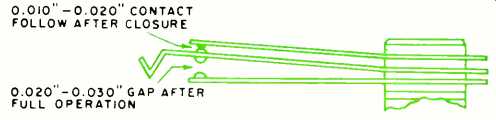
Fig. 4. Proper contact follow after closure and contact gap.
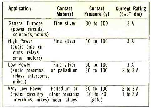
Table 1. Typical contact materials and their applications.
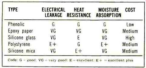
Table 2. Ratings of insulating materials in stack switches.
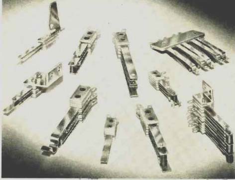
Fig. 5. Stack switches are available for variety of uses.
The selection of contact materials for various power levels is extremely important to the overall performance of the stack switch.
Silver, the most economical of the noble metals, is satisfactory when used in circuits with sufficiently high current and voltage to break through any film harrier. Silver contacts are frequently suitable for wetted circuits (that is, circuits in which d.c. "breakthrough voltage" is added to the a.c. signals). Palladium is an element of the platinum group, although harder and more resistant to mechanical wear than platinum. Most important, palladium is highly resistant to surface contamination and may be used in wet or dry circuits, making it suitable for both military and high-performance industrial applications. Palladium contacts are typically wedge shaped and opposing contacts are mounted at right angles. The vertical cantilever movement of the leaf spring produces a small but significant horizontal wiping action.
The advantage of using palladium is indicated by the fact that an average contact resistance of only 0.005 ohm is achieved, which is well within the limits required by MIL-J-41C for telephone jacks.
Part of the reason for such low contact resistance is that the palladium contacts are cross-bar welded to the leaf.
Furthermore, bond strength uniformity can be more reliably controlled on welded contacts than with riveted attachments.
A more inert contact material than palladium, one with very high resistance to contamination, is a special gold alloy. However, this material is not only more costly than palladium but is softer and more subject to mechanical deformation. With nickel backing, gold contacts may be welded to leaf springs. Typical contact materials and their application to various power levels are shown above in Table 1.
The selection of single contacts or twin-bifurcated contacts will depend upon the degree of reliability required. A substantial improvement is obtained by using parallel contacts rather than single contacts. When truly parallel, independent contacts will provide this improvement; the usual twin-bifurcated contact springs found in stack switches approximate the parallel contact arrangement. Twin or bifurcated contacts have a distinct advantage over single contacts at low energy or intermediate loads, while single contacts are usually employed for the switching of heavier loads.
Clean contacts are essential to reliable performance and the manufacturer's instructions should be followed regarding maintenance on the particular contacts furnished. Highly corrosive cleaners or highly abrasive tools can do more harm than good. Also, contacts may be protected by using diodes or RC networks for spark suppression.
The electrical insulation parameters of interest to the user are electrical leakage, heat resistance, and moisture absorption. Table 2 shows the comparative ratings of insulating materials that may be specified for stack switches.
Grades XX-P and XXX-P phenolic offer excellent insulation resistance and breakdown ratings and are typically furnished on quality units. Special environmental considerations, such as high heat, would indicate the use of silicone bonded mica insulators or else polystyrene insulators for high humidity environments.
Environmental Conditions
As indicated at the beginning of this article, stack switches are not intended to be used in applications where extreme shock, vibration, humidity, or temperature ranges are involved. Some steps may be taken, however, to provide protection against these conditions. For instance, in cases where vibration is a factor, back-up springs may be added to the stack. One of the special stack insulation materials mentioned earlier may also be provided. In any case, the user should clearly detail any environmental conditions that may be encountered when specifying the stack switch in order to assist the supplier in recommending a unit to suit the requirements. UL or CSA approval cannot be provided for stack switches since they become an integral part of the device in which they are mounted so approvals must be obtained on the entire assembly, and not just on the stack switch itself.
It is highly recommended that the circuit design engineer purchase or construct prototype switches for testing under actual conditions. While switch manufacturers can simulate environmental conditions in the laboratory, there is no substitute for testing under actual operating conditions. Some manufacturers, including Switchcraft, offer stack switch sample kits which permit the user to construct various assemblies for test and evaluation purposes.
Cost Factors
Reduced cost is one of the major advantages of stack switches. The cost per switching configuration is less than almost any other switching device, not to mention the added savings in simplified maintenance. Stack switches will typically price out between 15 and 20 cents per s.p.d.t. combination depending upon the quantity ordered, special forming, contact material used, and type of adjustment specified.
Fig. 5 shows stack switches which were designed for various applications. The versatility of these units minimizes extra design or tooling costs to meet special switching requirements. Note the special forms in some of the switches to achieve sequential operation or to accommodate various actuator designs.
Time-tested and proven in a multitude of switching applications, the stack switch can be specified with complete confidence that it will provide superior performance at minimum cost.
(source: Electronics World, Oct. 1967)
Also see: Snap-Action Switches and their Ganged Arrays