By RONALD G. REZEL /Supervisor, Commercial Switch Section
Specialty Products Div., Cutler-Hammer, Inc. [A native of Milwaukee, the author received his B.S. degree from Marquette University. In 1956, he joined the Specialty Products Division of Cutler-Hammer as a member of the Headquarters Sales group. In 1957, he was transferred to Jacksonville, Florida where he opened the company's sales office there. He returned to Milwaukee in 1960 as Headquarters Sales Supervisor and was named to his present position in 1961.]
These switches are among the simplest and least expensive method of providing control. Making the proper selection requires consideration of rating, size, terminations, as well as styling and assembly costs.
SELECTION of the proper "toggle-type" switch involves not only consideration of rating, operation, size, and terminations, but factors of styling, integrating functions, and assembly costs as well. The control switch should be made a part of the finished product rather than being just an afterthought.
Standard toggle switches are undoubtedly the simplest and cheapest method of providing control. Selecting the proper switch shouldn't be difficult considering the wide variety of standard switches on the market. UL-approved switches include ratings from 60 amperes or less at 251 to 600 volts and 2 hp or less at 600 volts or less, as listed in "UL Snap Switch Specifications 20 ". These are basic ratings and, from these same UL-approved switches, others below the 250-volt rating and above 2 hp can be engineered.
Unfortunately, designers often leave the engineering decision regarding the switch to he used on a product until too late in the design process. This is a mistake since it usually results in a compromise which often restricts the engineer's choice to a switch that may prove less-than-ideal for the product.
Ideally, consideration of the control should be started early in the design process to provide the best possible switch for the product. For example, in a dry-circuit (low-current) requirement, the switch should have a wiping contact in order to insure a good electrical circuit.
In an a.c. application, the best switch is an a.c.-designed device with slow make-and-break contact operation.
Operating Mechanisms
Proper evaluation of standard switches requires an understanding of the basic operating mechanisms available. In the toggle switch area (this also includes rocker switches) , the two basic mechanisms are the "teeter-totter" and "over-center spring ".
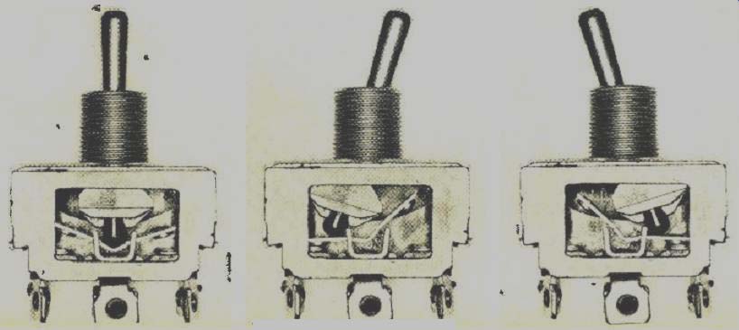
Fig. 1. The "teeter-totter" mechanism, designed basically for
a.c. circuit operation, can also be employed at low d.c. voltages.
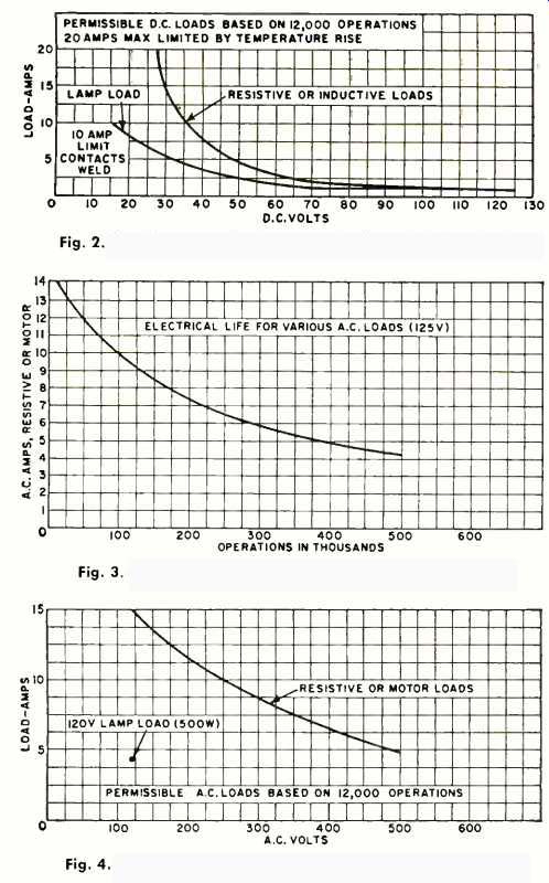
Fig. 2. Derating curves for d.c. operation for switch described.
Fig. 3. At lower loads, the life of the switch is extended.
Fig. 4. Higher voltages require reduced loads for given life.
The teeter-totter mechanism (Fig. 1) is basically an a.c. mechanism and is the most versatile type in that it permits a number of circuit variations. Such variations can be obtained by changing contactor shapes and contact supports. For example, a standard double-pole, double-throw switch with special contactors and a jumper can be used to provide three independent "on" circuits. Rating capabilities are generally up to 1 1/2 hp at 125 volts or 2 hp at 250 volts in single-, double-, three-, or four-pole configurations.
Fig. 2 indicates the Berating for this general category of switch in d.c. applications. At low-voltage d.c., this type of switch will outperform d.c.-designed switches in the same price category.
Due to the size of the contact area, this general type of mechanism can be modified with various precious-metal contact materials to provide additional rating capacities and adaptability to various lamp-load requirements.
Note should be made of life versus rating on this line of switches and Figs. 3 and 4 show the life and load curves that should be considered in applying these switches. It is important in today's competitive market that the control do the job and not be over- or under-designed for the product it is to control. Life requirements must be clearly understood, based on the load the switch will control and the market life needs of the finished product.
The "over-center spring" mechanism (Fig. 5) is generally considered the basic a.c.- d.c. mechanism. Although these switches operate on both a.c. and d.c., it should be noted that the quick make-and-break mechanism will not take advantage of the natural characteristics of the a.c. sine wave to help extinguish the a.c. arc. Consequently, if all that is needed is an a.c. duty switch. it is better to use an a.c.-designed switch rather than a dual-rated unit. At best, an a.c.- d.c. rated switch is a compromise design.
Ratings on the a.c.- d.c. mechanism go to 20 amp at 125 V on the heavy-duty mechanism and to 8 amp at 125 V on the light-duty mechanism in single- and double-pole configurations.
The light-duty mechanism is also the most common switch used on dry-circuit loads. (Dry circuits are those in which there is no arcing when opening contacts. In such circuits, voltage drop across the switch is below 50 mV and contact resistance must not exceed 200 ohms or below 10 millivolts where contact resistance must not exceed 50 ohms.) These switches, depending on the application, can be modified by plating the contacts with silver or gold or by using precious-metal inlays.
Ratings and Terminals
In all cases, the engineer must understand the ratings that apply to each type of switch. For example, on a.c.-d.c. switches, most such units have a per-switch rating.
On a.c.-only switches, however, many are rated per-pole, e.g., a double-pole switch rated “3/4 hp, 125 V a.c., 10 A 120 V, 15 A, 125 V" can be listed by UL with this rating on a per-pole basis-with each pole capable of handling this rating, or it may he rated on a. per-switch basis in which case the rating applies to the switch wired as a double-pole unit. There is no way an engineer can determine this by merely looking at the switch. He will have to get such information from the manufacturer or from the UL files since it is essential data when specifying switches.
Available terminals include screw, solder lug, quick-connect, wire lead, and plug-in lead. However, not all a.c. and a.c.- d.c. switches are available in all these terminations.
Most switches on the market today use phenolic molding material for the base and this allows a safe operating ambient temperature between -30° F and +160° F. Special molding materials and custom processing can increase the operating ambient temperature to 220° F.

Fig. 5. Two types of "over-center spring" mechanism toggle switches
are shown here in cutaway photographs.
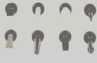
Fig. 6. Toggle switches are available with a wide variety of colored and
shaped operators to meet any requirement.
Insulation and Sealing
Another factor which is getting more attention in product design these days is double insulation. This means:
1. An insulation system comprising both functional insulation and protective insulation. Functional insulation is the insulation necessary for proper functioning of the device. Protective insulation is an independent insulation provided in addition to the functional insulation in order to insure protection against electrical shock in case the functional insulation fails. An enclosure of insulating material may form part or the whole of the protective insulation.
In such a system these two insulations, functional and protective, are mechanically separable and are so arranged that they cannot be subjected to environmental conditions simultaneously.
2. An improved functional insulation, referred to hereafter as reinforced insulation, of such mechanical and electrical properties that it is acceptable in lieu of a system consisting of functional insulation and protecting insulation. In enclosure of insulating material may form a part or TT-hole of the reinforced insulation.
At the present time there are no specifications governing double-insulated switches. However, many switches on the market can be modified to meet double-insulation standards in the finished product.
Sealed switches are generally provided by manufacturers of toggle switches by means of internal bushing seals.
However, with the introduction of rocker operators (actuating Mechanisms) and special styled levers, switch-sealing capability may be lost due to the inherent design of these operators. On the other hand, for certain critical operating areas complete environmental sealing can be provided.
Quite often, date to design needs, the switch manufacturers can provide added benefits to the engineer by customizing the control to the application. This is especially important in today's market where there is more and more emphasis on human engineering and space-reduction requirements.
In many industrial electronic applications it is necessary to provide controls which meet some of the requirement's of aerospace switches. Consequently, there is a need to modify commercial Switches to meet certain of the military specifications, such as temperature, shock, and vibration.
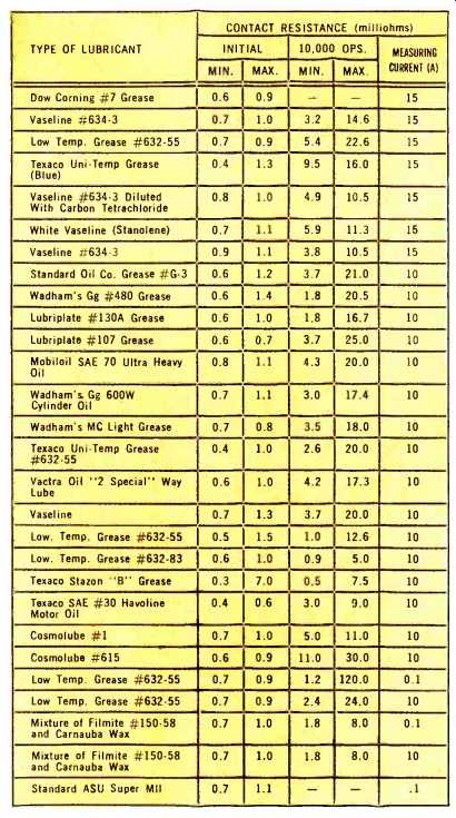
To show how one simple modification can change operational results, examine Table 1. This shows how contact resistance changes in a standard commercial double-pole switch with different lubricants. Changing the lubrication is obviously a minor change, but a review of this table will show the importance of this one factor.
By changing contact material, contact pressures, and base material, switch characteristics can be changed dramatically to suit specific operating needs. Also the trend to miniaturization is bringing about designs for smaller switches that will meet specific rating needs, with emphasis on size rather than maximum rating.
Various switch mechanisms call be equipped with special operators in different styles and colors. Paddle operators, rocker operators, push operators are some of the standard operators available today. As thermoplastics become more common in the design of switch superstructures, noire varieties will be made available (Fig. 6).
In the selection of switches, whether toggle, rocker, or Miniature, there is a need to choose the switch as an integral part of the design rather than as a final consideration. This will provide a better, less costly, integrated control for the product.
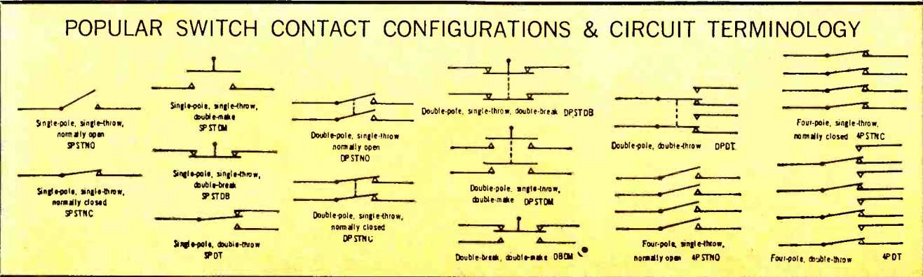
POPULAR SWITCH CONTACT CONFIGURATIONS & CIRCUIT TERMINOLOGY
(below) Table 1. The effect on contact resistance of changing lubricant:
(source: Electronics World, Oct. 1967)
Also see: Stacked Switches and their Ganged Arrays