(source: Electronics World, Apr. 1968)

By B.C. BIEGA /Director of Engineering Sola Electric Div., Sola Basic
Industries
The author is chairman of the Electronic Power Supply Committee of the National Electrical Manufacturers Association. A graduate of the Technical University of Warsaw, he worked several years in England before coming to the United States in 1951. He has worked in product engineering, application engineering, and has held management positions in marketing and manufacturing. He is a Senior Member of IEEE, a Registered Professional Engineer, and has a number of papers and articles to his credit.
In order to compare specifications properly, measurements should be made according to certain standards. Here are the proper methods to use to avoid measurement errors.
A GLANCE at the ads in any magazine devoted to electronics and instrumentation technology will indicate the availability of many types of electronic power supplies. Their power outputs--ranging from milliwatts to kilowatts--are designed to provide fixed or variable voltage or current with almost any desired degree of precision and stability.
Growth of the power-supply industry, in a relatively short time, has been so rapid that it has been necessary to develop a whole new terminology to describe the performance characteristics of these power supplies. Further, as circuits and components have been improved, specifications for regulation, temperature coefficient, ripple, and drift have become tighter and tighter. But, for lack of common terminology and definitions, the user is often unable to make meaningful comparisons of the products of two different manufacturers.
Recognizing this problem, a number of major power supply manufacturers are cooperating in the development of a Standard for Electronic Power Supplies through the Electronic Power Supply Committee of the National Electrical Manufacturers Association (NEMA) . The Standard will include sections covering definitions, ratings, safety provisions, and measurement methods. This Standard is expected to be completed late this year. Its adoption by all power-supply manufacturers will eliminate most of the existing confusion as to the exact meaning of the various specifications.
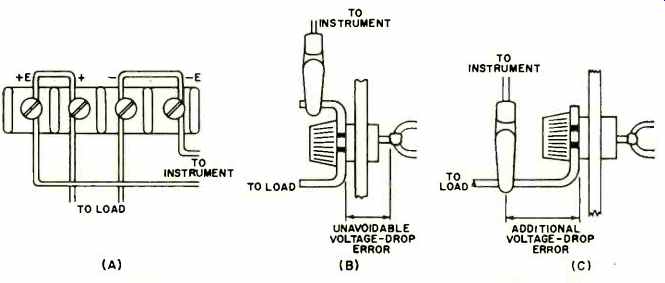
Fig. 1. (A) Proper lead connections to rear barrier strip. (B) Correct
and (C) incorrect connections to the front-panel terminal of unit.
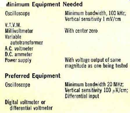
Table 1. Equipment needed to make power-supply measurements.
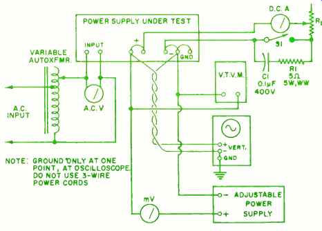
Fig. 2. Setup for measuring constant-voltage power supply.
Avoiding Errors in Measurement
The tighter the power-supply specifications, the more difficult it is to make measurements verifying spec conformance. This is so because measurement errors can become greater than the change in output being measured.
For example, if a power supply is rated at 24 volts output with 0.01percent load regulation, this means the terminal voltage varies no more than (0.01 /100) X 24 = 0.0024 V = 2.4 mV for a no-load to full-load change. If rated output current is 5 A, the internal impedance is (2.4 X 10⁻³) / 5 = 0.48 milliohm or 0.00048 ohm. The measurement of load regulation is, in effect, the measurement of this internal impedance--not an easy matter. Note that 1 inch of #20 A.V.G. copper wire has a resistance of 0.84 milliohm at a temperature of 20 °C. The contact resistance of an alligator clip may be much higher. Consequently, it is essential to eliminate any series voltage drops between the power-supply terminals and the point where the measurement is made, and to keep the current flowing in the measuring circuit leads as low as possible.
Most precision power supplies have a rear panel containing two pairs of terminals: one for output or load leads, the other for remote error-sensing leads. Connect leads as shown in Fig. 1A to obtain the most accurate results.
In power supplies with only one pair of front-panel output terminals, connect the measurement leads as shown in Fig. 1B, rather than as in Fig. 1C. Even with the proper connection, an uncompensated source of error exists in the voltage drop on that part of the terminal post extending through the panel.
Separate pairs of measuring leads must be run from the same monitoring points to each instrument, avoiding mutual coupling effects. The pairs should be twisted to avoid pickup and, in some cases, shielded leads may be necessary.
Instrument resolution must be at least one order of magnitude better than the smallest quantity to be measured.
For example, to measure down to 1 millivolt, the volt-meter must have a resolution of at least 100 microvolts.
Since the power supply being tested and the power supplies and amplifier in the measurement instruments all experience some drift or change during warm-up, it is essential that the equipment be energized, and the power supply connected to its load, for the specified warm-up time. If no specific warm-up time is indicated, allow a minimum of 30 minutes for the purpose.
Constant-Voltage Power Supplies
The most important measurements to be remade are line and load regulation, PARR (Periodic and Random Deviations) which includes both ripple and noise, and transient recovery time. Table 1 lists the minimum and preferred equipment needed.
Fig. 2 shows the test set-up using the "minimum" equipment. The variable autotransformer is used to vary the monitored input voltage to the power supply. Make sure the rating of the autotransformer is 20 percent higher than the total output rating of the power supply, since it must handle the power supply losses in addition to the load.
Load resistor RL must have a resistance and wattage rating capable of handling the maximum current at the maximum output voltage of the power supply. The v.t.v.m. is used to measure the power-supply output voltages while a d.c. ammeter is used to measure the output current.
Switch S1 is used for measuring load regulation. C1 and R1 are connected across the contacts of Si to minimize switching noise. A double-pole relay should be used for S1 since the second set of contacts can then be used for triggering the oscilloscope sweep.
The adjustable power supply is used to buck out the output voltage of the power supply being tested so that the zero-center millivoltmeter measures only the change in output voltage. The adjustable power supply must have an output at least as high as that of the unit being tested, but its power requirement is very small. Ripple content should be lower than that of the supply being tested.
If a high-quality 6-digit digital volt-ammeter or differential voltmeter is available, it can replace the v.t.v.m. and the bucking-supply /millivoltmeter combination.
Measurement Procedure: Energize the set-up at rated a.c. voltage. Adjust the power supply for maximum rated output voltage and adjust RL to draw maximum rated current.
If the power supply has an adjustable current limit, set it well above maximum current rating. If it has automatic constant-voltage /constant-current crossover, adjust RL so that the current is at 90 percent of the crossover point.
Check set-up for pickup and ground-loop effects by switching the power supply "off" and observing the scope first with its leads connected together and then to each of the output terminals of the supply. If any signal is observed on the scope, change lead routing and ground connections until the problem is corrected.
After the specified warm-up time, readjust R1, to obtain correct output current. Finally, adjust the bucking supply so that the millivoltmeter is nulled.
Line Regulation: Vary the input voltage over the specified range (usually 10 percent above and below normal) and record the millivoltmeter reading. This will provide AV, the absolute value of the line regulation, in millivolts.
Percent regulation = (AV /1000E) X 100 where E is the total output voltage, in volts.
For variable power supplies, repeat at various levels of output voltage. Also repeat with no load on the power supply.
Load Regulation: Switch the load "on" and "off" and record the change in output voltage, allowing time for re-establishment of equilibrium after each load change. Repeat for lowest and highest specified line-voltage settings. The calculations for percent regulation are the same as for line regulation.
Recovery Time: During the load-regulation measurement, an output voltage transient may be observed on the oscilloscope. Typically, it may appear as shown in Fig. 3A. If the dashed lines represent upper and lower limits of the specified transient recovery band, recovery time will be specified in the NEMA Standard as "time elapsed from the initial excursion of output voltage beyond the limit until it returns and stays within this band". Fig. 3B shows the case of an overshoot along with an undershoot. Unless otherwise specified by the manufacturer, the transient recovery band is equal to the regulation band and is centered on the average of output levels before and after load change.
PARD (Ripple and Noise): The PARD of the power supply output is a new and preferred method of specifying ripple and noise (periodic and random deviations) by indicating its maximum peak-to-peak value in millivolts.
The value can be observed directly on an oscilloscope (Fig. 3C) . The r.m.s. value of ripple, which is sometimes specified, may be two to four times lower in value, depending upon the waveform of the ripple component and the amount of noise present. The r.m.s. value may be measured by substituting a sensitive true r.m.s.-reading a.c. meter for the oscilloscope.
In order to detect high-frequency spikes on the output, a scope with at least a 20-MHz bandwidth is required.
In fact, a differential oscilloscope with special coax cables and connectors must be used to accurately measure the amplitude of high-frequency spikes.
Note that a 60-Hz component in the ripple is usually indicative of undesirable stray pick-up. This should be eliminated to obtain a correct measurement of PARD.
Constant-Current Power Supplies
To measure constant-current power supplies. variations in output current (due to input line or load variations) are changed to variations in voltage drop across a series sensing resistor R,. Then the procedures outlined for constant voltage power supplies can be followed. The observed millivolt values are divided by the value of R to obtain milliampere current deviations.
However, difficulties in obtaining accurate results are even greater here than for constant-voltage supplies. For example, if the rated output of the power supply is 10 A and load regulation is stated as 0.01 percent, the specified current change is actually 10 X 0.0001 = 1 mA. If the sensing resistor R, is 0.1 ohm, the voltage drop across it at rated current will be 1 V, while the change in voltage due to regulation will be 1 mV. This magnitude of change will also occur even in a precision resistor with a temperature coefficient of 20 ppm / °C if its temperature increases 50 °C during this test.
Therefore, the sensing resistor must be selected with a power rating of at least 10 times (preferably more) the power dissipated in it at full rated current. Its resistance value should be chosen to provide an approximate 1-volt drop at rated current. A higher value would help in making measurements, but would reduce the available compliance voltage of the supply and tend to increase the circuit resistance when load resistor RI, is shorted out during the load regulation test.
A good quality ammeter shunt or a precision wirewound resistor should be used. To avoid sudden changes in its temperature, it should be shielded from drafts and preferably placed in an oil bath. The sensing leads must be connected between the resistor and its load terminals, as shown in Fig. 4. Keep all sensing leads as short as possible.
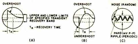
Fig. 3. (A), (B) Typical output voltage transients and recovery times. (C) PARD is specified in millivolts, peak-to-peak.
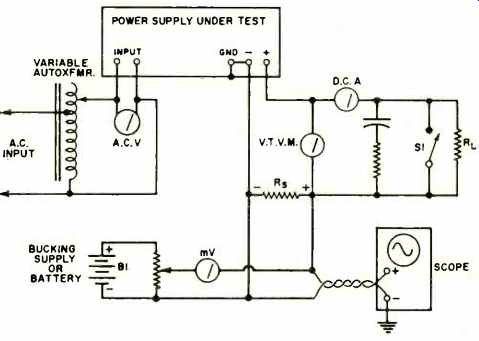
Fig. 4. Setup for measuring constant-current power supply.
Load resistor R1, should be selected so that the supply's voltage output does not exceed its permissible compliance voltage rating. In the case of constant-voltage / constant-current supplies with automatic crossover, the supply's voltage output should not exceed 90 percent of its constant-voltage operating value. It is desirable to use a fixed resistor of ample power rating here. Small resistance changes at the brush contacts of a rheostat will show up as additional noise in making the PARD measurement. The power supply voltage-limit control must be set at a level well above the maximum compliance voltage used in the tester.
Current flowing through the output voltmeter will show up as an additional load on the supply; therefore, a high-impedance v.t.v.m. should be used, connected as shown.
Note that switch S1 shorts out the load resistor when closed. Therefore, the load regulation test is made by switching from rated load to short-circuit load.
Temperature Coefficient & Drift
Temperature coefficient tells us how the regulated output is varied as a result only of changes in ambient temperature, and is specified in absolute change AV or as a percentage change, per degree centigrade. This variation is not generally linear and should be specified as a maximum rate of change that occurs anywhere within the specified operating ambient temperature range of the supply. To measure this coefficient, an oven with precise temperature control is needed.
The power supply is placed in the oven and the temperature control is varied in 10 °C steps over the entire specified range. After each temperature change, it is necessary to wait for the output to stabilize at its new level.
This may take about 30 minutes for each step. It is important to maintain all other parameters (such as input line voltage and load resistance) constant. Stability of the measuring instrument is an important factor in making accurate measurements. It is also desirable to retrace all temperature points in the reverse direction to average out any errors that may occur.
Drift is the maximum change of output over a period of eight hours with all other parameters held constant.
It is the most difficult characteristic to measure precisely, because unavoidable changes in the line voltage, load resistance, ambient temperature, and especially drift of the measuring instruments may have as great, or even greater effect on the measured supply output voltage or current than the inherent drift of the power supply itself.
Tests should be conducted with both the power supply and all measuring equipment held in an ambient temperature which varies less than 1 °C. Measurement of drift should not begin until initial warm-up is completed. The output and all other parameters (such as ambient temperature and input voltage) must he checked every few minutes during the eight-hour period. Obviously, strip-chart recorders are ideal for this purpose.