(source: Electronics World, Apr. 1968)
By EDWARD S. BRENNER / Director of Engineering Lambda Electronics Corp.
The author received his B.E.E. from City College of New York in 1957. He joined Lambda in 1963 as Senior Engineer in the Advanced Development Group, where he was engaged in research on high-powered SCR switching systems, high-stability, low-power circuitry, and studies in FET applications. Later he designed low- and high-voltage series pass regulated power supplies and was in charge of supplying application information and quotations for non-standard requirement; He was formerly Manager of Instrument Products.
To make an intelligent selection from the large variety of available supplies, the user must know the operation and the most important specifications that are covered here.
HOW WOULD YOU:
... Evaluate the effects of environmental change on a regulated current?
... Program a voltage inversely?
... Control very small currents ?
... Measure dynamic output impedance?
... Provide variable voltage limiting?
... Connect a feedback signal to a power supply from a temperature sensor?
... From a photo electric cell?
... Determine programming speed?
... Calculate the effect of duty cycle loading?
... Convert a source to a sink?
... Make a voltage corrector?
... Determine the effect of offset voltage and offset current on a power supply's output?
... Write the operational equation that controls feedback power supply behavior?
POWER SUPPLIES and power regulators can be represented by a wide assortment of devices ranging from batteries and generators to dynamic electronic-units using feedback. These include a large family of electronic converters: a.c. to a.c., d.c. to d.c., d.c. to a.c., and a.c. to d.c. Here we will be concerned with the a.c. to d.c. converter employing a series regulator.
Power-distribution systems usually use a.c. power because this power is easy generated and distributed. However, most system applications of power require d.c. power sources to energize the electronic circuitry. The specific function of the power supply is to provide substantially constant, ripple-free d.c. voltage and current from a primary source which is a.c.
Power conversion generally starts with rectification, a process which converts a.c.. voltage to d.c. voltage. Because the output of a rectifier contains a relatively large a.c. ripple component in addition to its d.c. value, a filter must be used to attenuate the ripple component before this d.c. power is applied to the load. Figs. 1A and 1B illustrate two filtering configurations while Fig. 1C shows the effects of these networks.
The amount of ripple present after filtering the rectifier output is a function of the components used and the load current. No matter how efficiently ripple is reduced, the rectifier-filter d.c. output can change substantially with load current and/or power-line variations. Control of these variations is defined as power-supply regulation.
The demand for better regulation imposed by today's sophisticated circuits and complex systems can be met more effectively by the regulated or. feedback-controlled power supply. Regulated power supplies are capable of maintaining a substantially constant output voltage at some selected value, even though changes occur in the a.c. supply voltage (within specified limits) and /or in the rated d.c. load current. In addition, these power sources can be made short-circuit-proof, preventing damage to the supply caused by the load, and can he made load-protecting by utilizing overvoltage protectors, which prevent load damage caused by internal supply failures The greatest demand for power supplies is in low-voltage (less than 100 volts) semiconductor applications, creating a market exceeding $100 million. The power supplies for this market are generally all-solid-state designs with more recent models using silicon semiconductors for high reliability and greater power-handling capacity per unit volume.
Power-supply packaging is dictated more by function than by appearance. Modular or system-type power supplies are available for various mounting configurations.
Multiple-output power-supply systems can be assembled using modular power supplies and metered panels in rack adapters.
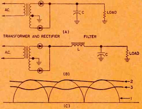
Fig. 1. Rectifier and filter configurations showing (A) capacitor and
(B) LC filters. (C) D.c. output voltage waveforms for single-phase, full-wave
rectifier with (D) no filter, (E) capacitor filter, and (F) LC filter.
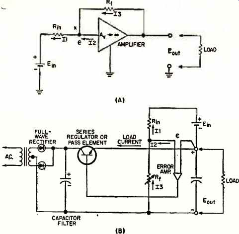
Fig. 2. (A) Operational amplifier. (B) Regulated supply.
Some supplies can be used for either laboratory or system applications. When used in electronic systems, the rubber feet can be removed and a rack adapter provided for convenient mounting (as shown in photo on page 39) . High-powered. full-rack regulators can be supplied with rubber feet that are suited for laboratory and bench use.
In most cases, the user will find the power supply he requires from some manufacturer's "off-the-shelf" catalogue. To the user, this means that the device is readily available as a standard product with minimum delivery time lapse. Standard product lines include supplies with ratings from the milliwatt range to units with ratings exceeding 10 kW. The price may be well under $100 or well over $5000, depending upon the power capacity and performance characteristics required.
Operating Principles
The series-regulated power supply belongs to a family of circuits referred to as d.c. operational amplifiers. These are extremely high-gain amplifiers that use feedback to control their output function and are capable of operating from d.c. to some finite limit in frequency. We will mainly concern ourselves with d.c. operation. See Fig. 2A. The open-loop gain of the amplifier (Ar) is very large and assumed to be near infinity compared to the closed loop gain or gain with feedback. Values of A, on the order of 100,000 are not uncommon. In order to generate an output signal of magnitude Eout, an input or error voltage (E) of Eons /A, is required. Since A, is many orders of magnitude larger than Eout, the error voltage can be considered to be zero. Using this approximation, we can then state that I1 = Ei /Rin and I3 = Eout /Rf because e is at zero or virtual ground. Also, knowing that currents entering a node must equal currents leaving a node, we can sum the currents around node X and obtain I1 = I2 + I3. Generally, a system must be designed with /2 many times smaller than either I1 or I3, so that essentially I1 = I3.
Consequently, Eout /Rf I1, and Eo t /Ei = I1Rf /I1R;
= Rf /Ri = closed-loop gain. Hence, closed-loop gain is a function of external components Rf and Ri , as long as Ao is much larger than Rf /Ri and I1 is much larger than I2.
We now rearrange Fig. 2A to satisfy the circuit requirements of the series-regulated power supply, shown in Fig. 2B. Although this is basically a model of a power supply which can be operated over a wide voltage range starting from zero volts (zero supply) , the theory is applicable to narrow-range (slot) supplies.
In the power supply, the error amplifier and pass element together are equivalent to the entire operational amplifier of Fig. 2A. A full-wave rectifier and a capacitor filter provide "B + voltage for the pass element. The error amplifier is normally powered by an auxiliary bias supply.
The input voltage, Ein, is created by a stable zener reference element using a compensated current source to supply it with constant excitation current. Similarly, the output of the power supply is: Eot = Ei Rf /Rin, The output can be changed by varying either Rf or R1 . Varying /tin would then cause a variation in the current I1 supplied by Etn. A change in I1 causes a change in Ei because the stability of a zener diode is dependent upon specific constant operating conditions. Because varying Rf has no effect on I1, it is the preferred method for varying output voltage.
Most supplies can vary the feedback resistor, Rf, from a remote source either by providing a pair of terminals in series with Rf or by replacing it entirely. Both methods permit control of the output voltage from some point far removed from the regulator location. This is referred to as remote programming. Since Il is a constant, the power supply user can easily program the output voltage linearly by varying the feedback (or programming) resistor. As would be expected, a supply should only be programmed within its rated limits of operation.
Operating Parameters
Let us examine the important power supply operating parameters, relate them to circuit performance, and investigate their limitations.
Load Regulation. Load regulation is defined as the amount the output voltage will vary for a specified change in load (output) current. It can be seen from Fig. 2B that load current is supplied by the pass transistor to the load. Because a transistor is a current-amplifying device, the current required at the base of the pass transistor is only a small fraction of the load current. The change in the error amplifier input current (12) required to supply this base current is extremely small and normally less than a microampere. This change in input current causes a change in the error voltage (e) which is the main factor affecting load regulation. For the circuit shown: delta_Eout = delta_E (1 + Rt/Rin)
Load regulation depends upon two components, then; one a constant and the other a proportion of output voltage. The constant component is more important when a supply is operated at or near zero since, under these conditions, Rt /Rin would be essentially zero. When the power supply operating point is such that Rt /Rin is much greater than unity, the variable component of regulation predominates. Because power supply output requirements do vary, the user must recognize the need for specifying load regulation in two quantities. The series-regulated power supply will typically have a variable regulation band of from 0.01% to 0.1% of output voltage and a fixed component of from 1 to 5 mV for load current changes of from no load to full rated load. Values above and below this band normally are considered poor and good regulation, respectively.
Line Regulation. This parameter defines how much the output voltage will vary for a specified change in a.c. input voltage. This change causes a number of variations within the supply, e.g., "B + for the pass transistor changes, the error-amplifier bias supply voltage changes, and the reference zener diode (Ei) current source changes.
Because the pass transistor is within feedback loop, a change in its "B + potential will not cause an appreciable change in Eout. Referring to Fig. 2B, the minimum capacitor-filter voltage must be equal to or greater than the maximum output voltage plus the pass transistor saturation voltage plus any internal voltage drops around the power loop, plus the peak ripple voltage across the capacitor-filter. Any capacitor-filter voltage less than the sum of these voltages will cause the pass transistor to become saturated, resulting in loss of control of the output and causing the excessive ripple of the capacitor-filter output to appear across the output terminals.
At the high end, the a.c. input is limited by the amount of power the pass transistor can dissipate. For a given load current, the power in the pass section will be a maximum when the difference between the capacitor-filter voltage and the output voltage is a maximum since this difference appears directly across the pass transistor. When developing the power rating for a unit. the power supply manufacturer starts by selecting a reasonable a.c. line variation (usually 105-132 V r.m.s.) , and then designs a transformer to deliver maximum output voltage at full load with low line input. Power dissipation capability required with maximum input line voltage and minimum d.c. output voltage determines package size because the power circuitry required for dissipating the excess power contributes largely to physical size. Its direct contribution to over-all gain and regulation is relatively small.
In addition to voltage variations, the a.c. input can also cause frequency variations. Normally a power supply is designed to operate over a wide input frequency range.
The lower limit will be determined by either excessive transformer heating or increased ripple across the capacitor filter. The lower limit can usually be extended by reducing the maximum load current requirement. The upper limit is determined by a reduction of input voltage due to transformer leakage inductance or by increased output noise. Series-regulated power supplies are, in most cases, operable from 45 to 440 Hz. The effect of frequency variations on regulation is usually negligible.
Ripple and Noise. Fig. 3A illustrates a typical ripple and noise pattern at the output of a series-regulated power supply. Three distinct signal sources are detectable: (1) random noise generated by the reference zener and error amplifier as characterized by the thickness of the line; (2) ripple attributed to the line frequency, which has its origins in the reference zener bias circuit and pickup in the circuit wiring; and (3) low duty cycle spikes synchronized to the line frequency, which are generated by the input rectifiers and transmitted to the output.
These spikes are normally reduced by using r.f. attenuation techniques.
To properly describe this over-all a.c. component at the d.c. output requires an r.m.s. as well as a peak-to-peak limit.
Temperature Coefficient (TC). The amount the output voltage of the supply changes in proportion to the ambient temperature (with all other operating conditions remaining constant) is expressed as the TC. The TC is mainly dependent upon the closed-loop parameters of the supply. Changes within the amplifier after the first stage caused by temperature variations can normally be neglected (assuming that the magnitude of these changes is within the dynamic range of the amplifier) since the effect reflected hack to the input would be attenuated by the gain of the subsequent stages. Acceptable TC's are normally less than 0.05 % / °C+1 mV / °C. Because load and line changes cause dissipation within the supply, internal ambient temperatures will vary independent of external ambient changes. Such variation could be from 10 °C to 40 °C at different locations within the package, depending on component layout and thermal properties. The effect would be the same as changing the external ambient temperature. This effect is not specified on a manufacturer's power supply data sheet because its calculation depends on the user's techniques for ventilating and /or cooling, together with the magnitude of the user's line and load changes. However, it should be taken into account by system designers who use power supplies in large quantities in restrictive environments.
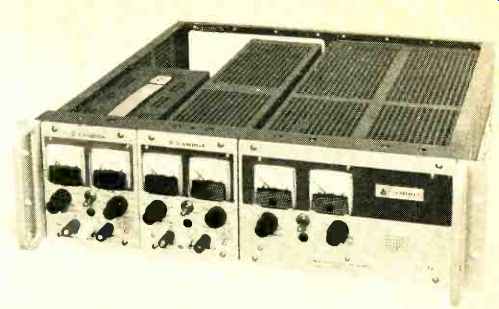
---- Three laboratory power supplies mounted in rack adapter.
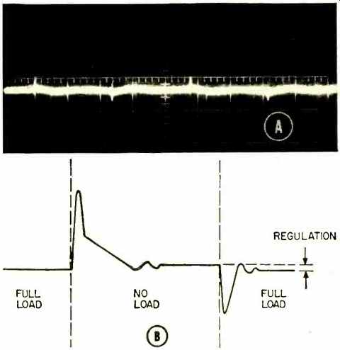
Fig. 3. (A) Waveform showing typical ripple and noise. (B) Transient
response of series-regulated power supply.
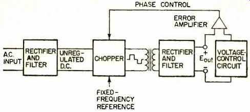
Fig. 4. Efficient phase-modulated switching power supply.
Recovery Time (Transient Response). A power supply will usually be required to operate into a varying load, with extremely fast variations in relation to the response time capabilities of the power supply circuitry. Hence, power supply output terminals are shunted by a capacitor, which supplies reserve energy when operating into rapidly varying (transient) loads. Fig. 3B illustrates the transient response time of a series-regulated power supply. Changing from a full-load to a no-load condition results in an output voltage spike caused by the inherent inductance of the internal and external circuitry. Simultaneously, the power supply still supplies load current to the output capacitor until the amplifier regains control. This causes the output capacitor to be charged to a voltage higher than the desired output voltage. The power supply's internal circuits will then bleed off this excessive charge until the output voltage reaches the selected level. Going from no-load to full-load first causes the load current to be drawn from the output capacitor since the amplifier cannot respond immediately to the changed power requirement. When the amplifier again regains control, the capacitor is recharged and the desired output voltage is restored.
It is apparent that the nature of the load can have a significant effect on the transient response characteristic.
A highly capacitive load will cause small peak excursions but relatively long settling times, while a highly inductive load will have just the opposite effect on these characteristics. Transient response is normally specified as the time required to return and stay within specified voltage limits surrounding the regulation band. For instance, a typical specification would be 100 As to be within 100 mV of the regulation band. This specification refers to a resistive type load, where error sensing is done at the power-supply output terminals.
Stability. Assuming that a power supply is operating from a constant input line and into a constant load while installed in any environment with fixed ambient temperature, small deviations, or drift, of its output voltage can be observed. This drift is referred to as the stability characteristics of the power supply. Even when operating under constant conditions, the power supply creates ambient differentials within isolated portions of its circuitry.
Thermal currents thus created cause variation in temperature-sensitive components and mechanical stresses in critical potentiometers resulting in output variations.
Easily available components used in today's circuitry will yield an output voltage stability of 0.1% or better for 8 hours after an initial warm-up period.
The power supply is a complex instrument, capable of many performance options and features. Consequently, a suggested model should be analyzed for intended application to insure the most economical and efficient handling of the customer's requirements. A convenient way of specifying performance is to select a regulation band which encompasses all the static operating conditions. This involves specifying upper and lower limits for each of the operating conditions.
There are many other specifications applicable to power supply use: environmental specs describing vibration, shock, temperature cycling, and humidity limits, as well as specs for radio-frequency interference generation.
Whenever a standard model cannot meet a user's needs, a specification can be generated by the user, tabulating performance goals and physical requirements. This normally requires liaison with a power-supply manufacturer's applications engineer who will insure reasonable specifications and a clear understanding of the problems involved in creating a modified or custom power supply.
Other Types of Regulators
The series-regulated power supply is the most widely used type. Its major attributes are versatility and excellent performance; however, its greatest drawback is its low efficiency. When the input and /or output vary widely, the efficiency can be as low as 25% and not much better than 50%. For example, a 5-volt power supply with a ±5 %0 output variation and a line voltage specification of 105 to 132 V r.m.s. will have a typical worst-case efficiency of 2.5% caused by the combination of high line input, low-voltage output with full-load operation. The efficiency can approach 50% for units with higher voltage ratings but will not rise much higher. The internal power dissipation can become excessive in uses requiring large amounts of power in a single system.
A partial solution to the problem is to utilize a method of power control employing switching techniques. This method, in turn, causes deterioration in such performance characteristics as response time, ripple, and noise, in addition to causing increased RFI. Recognizing these deficiencies, a user can obtain operating efficiencies exceeding 70 %. In such circuits, a different and more efficient power control mechanism is substituted for the series regulating pass transistors.
One such technique is the use of line-voltage phase modulation with SCR's as discussed elsewhere in this Special Section. Another widely used high-efficiency system for power conversion is illustrated in Fig. 4. In this method, the a.c. input signal is first converted to unregulated d.c., then a chopping or switching circuit, controlled by a feedback loop, is used to produce a fixed-frequency output.
The power is controlled by varying the duty cycle of this fixed-frequency output. A regulated d.c. output is obtained by rectifying and filtering this phase-controlled signal.
The chopping frequency is normally many times higher than the input line frequency. This factor allows the use of a smaller isolation transformer which, in turn, makes possible the attainment of high voltages while using low voltage control devices because the maximum output voltage then becomes a function of the transformer. Either SCR's or transistors can be used in the chopper section.
SCR's handle large quantities of power but are limited to an operating frequency of about 10 kHz. Transistors are limited in power-handling capabilities but operate at faster chopping rates. This provides better response characteristics than SCR systems.
Making the Choice
When selecting a power supply, the user should evaluate three main factors: Electrical Specifications. Consider the entire band of regulation desired instead of one or two attractive published specifications. For instance, a line or load specification of 0.005% is inconsistent with a temperature coefficient of 0.05%/ °C. A power supply should be capable of operating with substantial input line variations. The load should be analyzed for severe demands such as those required by lamp filaments, motor windings, capacitor and pulsed loading. The performance of the power supply should then be evaluated accordingly. Special features and protective circuits for the load and for the supply should also be considered.
Mechanical Specifications. Intended usage should govern the physical appearance of the power supply. A laboratory supply should possess a full complement of meters and accessible controls whereas a system supply must be compact and adaptable to what may be a difficult mounting requirement. When necessary, system mounting can be provided together with accessible controls. The interior power-supply layout should allow convenient access for servicing or internal calibration and adjustment.
Thermal Environment. Power supplies, by the very nature of their use, generate heat. Control of temperature build-up can be accomplished either by convection or by forced-air cooling. Control becomes a critical factor when a power-supply rating is based upon the operating ambient temperature. When installed in large systems, the power supply presents a problem of great concern to designers. The units must be situated so that they do not heat up critical system components, yet they must still be capable of dissipating their generated heat into surrounding external ambient. For laboratory use, the power supply must possess no external heat sinks that can harm the user and cause damage to other equipment.
Before selecting a power supply, a careful check list should be made based on intended usage. Because a large capital expenditure can be involved in the supply and the circuitry dependent upon it, a selection must be carefully made based upon good judgment, intended use, and economics. Such an approach to selection is feasible only if all the characteristics associated with the product are understood and evaluated.