(source: Electronics World, Apr. 1968)

By PAUL S. BIRMAN /Applications Engineer, Kepco, Inc.
The author is engaged in the development and marketing of d.c. regulated power supplies. He is the author of the "Kepco Power Supply Handbook" and various magazine articles on regulated power supplies. Prior to his association with Kepco, he served with the Army Ordnance Corps, attached to the Army Rocket & Guided Missile Agency (AROMA), Research Branch, at Redstone Arsenal, Alabama. Preceding this service, he did circuit design in d.c.-d.c. power supplies with Universal Transistor Products Corp. of Long Island. He holds a BSEE from the Polytechnic Institute of Brooklyn.
The feedback circuit of the regulator section is well suited for use in adjusting the supply's output. Such adjustment, called programming, may be done either locally or at a remote location.
REGULATED power supplies are often used in circuits and systems where the ability to control, vary, or modulate the output is required. A remarkable property of the regulator section of the modern power supply is that its feedback mechanism is just as well suited to the problem of control as it is to the maintenance of a constant output voltage or current. The process of varying a power supply's output is called programming.
The output of many power supplies may be programmed by varying a resistance--or a conductance--or by applying a signal voltage or current. These, in turn, may be shaped or controlled by a variety of function generators, motor-driven devices, or may be output-related to the power supply itself to close a feedback loop.
In general, programming is limited to those power supplies whose design does not depend on mechanical aids to dissipation limiting. For example, units employing variable autotransformers as part of their control will normally be incapable of electronic remote programming (except by the use of motor-driven or similar mechanisms) . Similarly, some power supplies that employ range switching-where that switching involves transformer taps-will usually be limited to external control within the span of any one range.
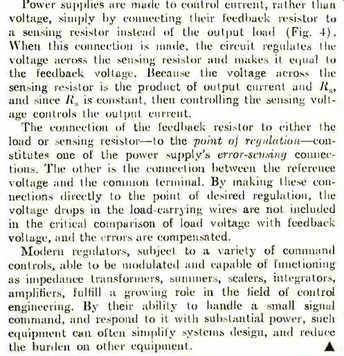
Error sensing is also provided with most precision power supplies to allow the equipment to feed back its corrective signals over a wire path separate from that used to deliver current to a load. This allows a power supply to include the drops in its load wiring as part of its own internal resistance, joining, among other items, the transformer resistance and rectifier drops. The process of compensating for an unwanted drop in the load circuit may be considered a form of restricted programming in which the supply programs itself by the needed amount. Even power supplies using mechanical control and otherwise not considered programmable, will have a 0.5 to 1-volt programming range for the sensing circuit. Simpler power supplies lacking feedback control mechanisms will, of course, not have even the degree of programming needed for remote error sensing.
Analysis of a power supply in terms of its signal flow rather than its power flow may be aided by a symbolic diagram (Fig. 1A) which reduces the supply to three basic elements:
1. A raw d.c. source, the output of a transformer, rectifier, and filter.
2. A regulator element, typically a tube or transistor, in series with the raw d.c. (An equivalent analysis could also be drawn for a shunt regulator.)
3. A high-gain d.c. comparison amplifier connected to drive the regulator in such a way as to maintain a null (zero volts) across its input terminals. (If the amplifier has sufficiently high gain, its feedback voltage is practically the same as its output voltage so that its input voltage is vanishingly small, or essentially zero. -Editor)
The amplifier input and the power supply's negative output form a feedback pair of terminals so that the output voltage will always be equal to the voltage across this pair (to maintain the input "null") . Several properties of the feedback pair are significant.
1. It passes negligible current into the amplifier and, therefore, possesses an apparent high impedance.
2. Any voltage achieved across the feedback pair will program the power supply's output one-for-one. Programming, then, becomes a matter of controlling the magnitude of the feedback-pair voltage.
Methods of Programming
The simplest method of programming involves placing a voltage source directly across the feedback terminals perhaps a battery controlled by a potentiometer (Fig. 1B). Because of the high impedance, the potentiometer's wiper will not be loaded, yielding good linearity vs position.
Programmed in this way, power supplies are sometimes used as impedance transformers. With "input" impedances in the megohm range and output impedances in the milli ohm region, transformation ratios from 10^9 to 10^12 ohms are common.
Becoming a bit more sophisticated, the feedback voltage might be controlled by placing a resistor across its terminals and contriving to pass a current through it. The IR product voltage will then program the output to an equal, but opposite, level. The current for the feedback resistance may be obtained from a separate source. If this current is constant, then the power supply's output voltage will simply be proportional to the resistance. For example, if the current is 1 milliampere, the output will be 1 volt for every 1000 ohms of feedback resistance. This is often called the programming ratio; 1 milliampere control current corresponds to 1000 ohms per volt, 2 milliamperes will give 500 ohms per volt, etc.
Output may also be controlled by varying the current; or the current and resistance may be varied simultaneously with the power supply's feedback circuit by simply multiplying the two, with the product being the power supply's output.
The current for the feedback circuit can be generated by connecting a current source across the feedback resistance (in which case the current generator must be capable of supporting the output voltage) or it may be connected across the amplifier's null terminals. Since the null terminals support little voltage (because of the gain) , this pair appears to have a very low, almost zero, input impedance, and so is easily driven by a current source. Since the current does not flow into the amplifier itself, the path takes it through the feedback resistor where its passage generates the IR drop needed to program the power-supply's output (Fig. 1C) . A current source in this position is readily simulated.
Because the amplifier's input impedance is nearly zero, any voltage in series with a suitable resistance can be used to generate the needed current. (Since there is no voltage across the input terminals, the effective impedance across these terminals is close to zero. This nearly zero input impedance should not be confused with the very high "input" impedance of the feedback pair shown previously in Fig. 1B.Editor.) The current will be the input voltage divided by its series resistor. This current, and thus the current through Rf, is subject to control by varying either the source, E,. (the reference) or its series resistor, Rr. Control will be directly proportional to Er and inversely proportional to Rf. (It is directly proportional to the conductance Gr = 1 /Rr.) Writing the complete equation: E,= Ef = Er (Rf /Rr) . The resistance ratio Rf /R, is sometimes called the operational gain. or closed-loop gain. When either Rf or Rr is varied to control output, the operation can be considered equivalent to varying the gain of an amplifier with a fixed input (Er) . If the gain ratio is allowed to remain constant, output may be varied in the selected proportion by controlling Er.
Er may, of course, be any voltage level as long as it is used in series with the appropriate resistor to produce the control current. The current needed will be dependent on the value selected for Rf, with larger values requiring the least amount of current.
In most modern power supplies, a shunt-regulated zener source is commonly used to produce the stable reference (E,.) . The current from it is determined by a precision series resistor (Rr) and is customarily between 1 mA (1000 ohms per volt) and 10 mA (100 ohms per volt). The feedback resistor (Re) is made variable and is mounted on the front panel and labeled "voltage control ". To qualify as a remotely programmable power supply, these elements are connected to the circuit via appropriate terminals and links, so arranged that users have access to any or all elements for the substitution of external components (Table 1). Programming mechanisms ]night include a remote feedback resistor which is variable, stepped, sequenced, or driven by a motor; or it might include au external source of voltage substituted for the reference. This, too, may be variable, derived in whole or in part from a function generator, sweeper, or sensor output for process control.
Next, let us consider sonic of the important design parameters that are involved.
The ability of a power supply to make its output follow a program accurately. linearly. and with good resolution is largely a function of the comparison amplifier's gain.
The higher this is the more nearly perfect is the comparison. The gain is usually reflected in the power supply's load regulation rating with 0.1. to 0.01% supplies requiring 80-100 dB of amplifier gain. Actually, the significant gain is the open-loop gain (A) less the closed-loop gain (Rf /Rr). The balance is called the "loop gain" or feedback return ratio.
Also involved is an analysis of accuracy or linearity are the amplifier's offsets (residual input voltages and currents) whose presence must be accounted for in deter mining the precise output.
With modern emphasis placed on varying output (rather than the traditional power-supply role of maintaining constant output) , the question of a power supply's dynamics (behavior while varying) becomes significant.
Typically, power supplies have used large capacitors across the output terminals. These capacitors are characterized by high energy storage, low a.c. impedance, and resistance to voltage change, making them ideally suited to the demands of the classical constant-voltage power supply.
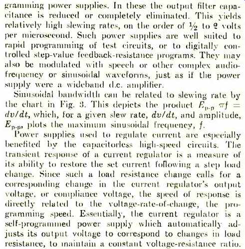
These same characteristics, however, make the traditional output capacitor unsuited to the demands of a variable (modulated) power supply. In particular, the capacitor affects the programming speed-or stewing rate, the rate of voltage change following a step command. say from a switched feedback resistor. (Slewing rate is measured as the chord from the origin to the first time-constant on the exponential response to a step command, as in Fig. '2.) The relationship I = C dv /dt, where dv /dt is the voltage rate-of-change, limits the clewing rate to the current divided by the capacitance. Typically, for most output filtered supplies, this will be just a few hundred volts per second.
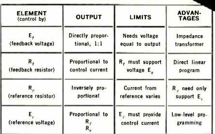
Table 1. Programming is done by varying one of these elements.
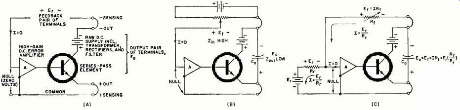
Fig. 1. (A) Simple series dissipative regulator type of power supply
showing signal voltage relationships. E., equals Er. (B) Voltage repeater
1:1 programming produces impedance transformation from very high-Z input
to very low-Z output. (C) A voltage Er in series with R, produces a current
through Rr equal to Er /Rr.
This current times Rr produces program E., = Er 1Rr /Rr1. Current arrows show direction of electron flow.
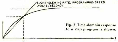
Fig. 2. Time-domain response to a step program is shown
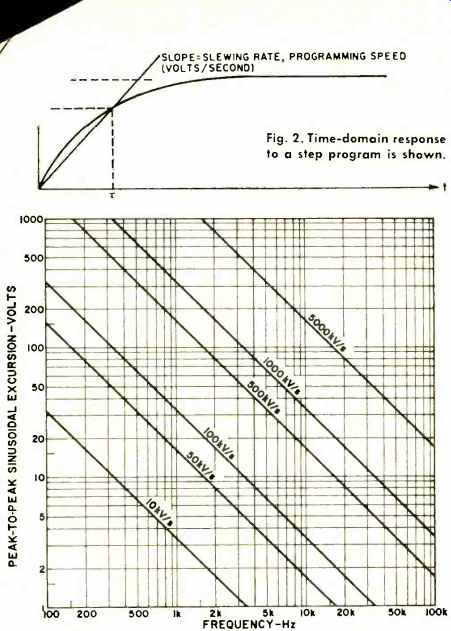
Fig. 3.
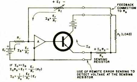
Fig. 4.
Fast-Programming Supplies
Some manufacturers now offer high-speed, or fast-pro-