(source: Electronics World, Apr. 1968)
By ARTHUR M. DARBIE /Marketing Manager Harrison Div., Hewlett-Packard
The author jointly holds two patents in power-supply circuitry, one of which involves protection features in a voltage-extending circuit known as the "piggyback" design. He holds BSEE and MSEE degrees from Newark College of Engineering. He is active in power-supply applications engineering and in contributing to that current NEMA meetings on standards in power supply specifications and definitions. He has been associated with the company (then known as Harrison Laboratories) since 1955; previously he was with the Television Research Dept. of Bell Labs.
Fuses and circuit breakers are much too slow for adequate protection. Hence, electronic circuits must be used to safeguard the supply and its load.
SOLID-STATE devices can break clown in microseconds as a result of over-voltage or over-current. The traditional fuse and circuit breaker take much longer to respond to current and voltage excesses. Hence, protection circuits must be incorporated into modern regulated power supplies which use all-semiconductor circuitry.
It has always been necessary to protect the power supply when voltage or current gets out of hand; but more important, a power supply must have circuits (or devices) that protect against ruining the load as well. (One recent example: a $300 power supply failed and ruined several thousand dollars' worth of IC's then under test.)
Current Limiting-The Basic Protection
Fig. 1 shows constant-voltage /constant-current (CV /CC) design, which contains all the basic elements for providing current-limit protection. The a.c. input passes through a power transformer and rectifier; filtered d.c. appears across filter capacitor C1. A series regulator, consisting of one or more power transistors, controls the flow of current through the output terminals and maintains a constant output voltage.
The series regulator is controlled by one of two comparison amplifiers; one for constant-voltage control, the other for current control. The voltage-comparison circuit compares a fraction of the output voltage with the reference voltage, and changes the conduction of the series regulator to hold the output to the desired value. The feedback loop works to maintain a zero difference between the two comparison amplifier inputs. The reference voltage is usually developed across a temperature-compensated zener diode which is powered independently, as shown. The current amplifier action is similar to that of the voltage amplifier.
With the voltage across RM held constant by feedback action, the current through RM (which is the output current) must be constant.
The two comparison amplifiers cannot operate simultaneously. For any given value of load resistance, the power supply acts either as a constant-voltage source or as a constant-current source. Transfer between these two modes is accomplished automatically at a value of load resistance equal to the ratio of the output voltage control setting to the output current control setting.
Fig. 2 shows the ideal CV /CC curve; here the comparison amplifiers in both circuits have been designed for tightly regulated performance. Moreover, the controls in each are variable, and a precise protection limit exists for any load against both voltage and current runaway-and in a matter of microseconds.
By relaxing the design requirements in the current-comparison loop, the designer can reduce costs of manufacture and still obtain almost identical protection by variable current limiting (CV /CL) . The slope of the limit characteristic is fairly steep, but not exactly vertical as in constant-current operation. In still less expensive supplies, the current-limiting function is less precise, and is not adjustable.
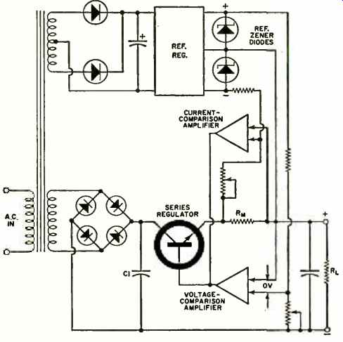
Fig. 1. Constant-voltage d.c. power supply showing additional circuit
elements required for constant-current (CV/CC/ operation. Circuit is essentially
self-limiting and self-protecting. Variable controls are for setting output
voltage and current.
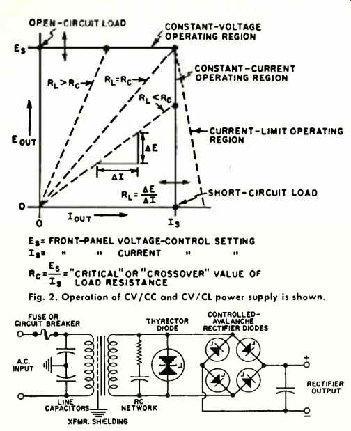
Fig. 2 (top), Fig. 3. (above) Devices for guarding against line-voltage
transients.
Another form of current limiting produces current cutback when maximum voltage aunt current threaten the series regulators. Here, when the entire output voltage falls across the series regulator, output current as well as output voltage chop to some fraction of their former limiting values.
Note that in variable current-limiting models, one can obtain constant-current operation by re-strapping rear terminals to reconnect the high-performance constant-voltage amplifier into a constant-current configuration. However, this mode sloes not offer the variable voltage ceiling useful for constant-current loads as would be the case with CV/CC supplies.
Other current-limiting 'techniques are used. One incorporates a "back-up" current-limiting circuit. This usually has a fixed limit value and acts only in the event that the first current-limiting circuit fails. Another current-limiting technique is to employ current-limiting saturable or adjustable transformers.
Safeguards Not Inherent in CL Designs
There are external conditions (such as sudden load, line, or controlling changes) which are not inherently protected against in CV /CL power supply circuitry. Further. internal conditions to watch for are failure of power transistors in the series regulators, or malfunctions in either the current or voltage-feedback loops. A failed series regulator usually shorts and causes full voltage and current at the output. A malfunction in the voltage-control loop can cause voltage to run away (without exceeding the current limit) , possibly destroying the output capacitor or load, and beginning a sequence of further failures within the supply. Current controls that open remove the current limit.
The ultimate step-for foolproof protection of the load and supply-is an independent circuit to provide fast clamp-down action at the output terminals. This is commonly called a "crowbar" circuit and is discussed later.
Additional Techniques for Protecting Supply
Programming surges can occur when the system status suddenly changes and causes voltages to exceed the low input levels of the supply's feedback amplifier. .-\ pair of clamping diodes can be inserted at the amplifier input to limit. voltage surges of either polarity to less than about 1 volt.
Reverse polarity can occur when the supply is hooked up either to a highly charged load or to other power supplies in series, with the power supply turned off. A diode across the Output may then be used to offer a low-impedance path to such reverse voltage and prevent any harmful effects in the power supply.
Similarly, when another supply is connected in parallel with the first (for greater output current) , there may be a voltage reversal across the series regulator. Here again, a diode across the series regulator limits the reverse voltage and minimizes damage.
Heat-sinking, of course, is a standard technique for getting rid of what might be excessive or damaging heat. An additional refinement is to employ a heat-sink thermostat which opens the circuit at the series regulator upon reaching critical temperature. This is a good safeguard against high ambient temperatures which could cause internal damage to the power supply.
A power supply should also be designed to fend off unwanted line voltage transients. A number of devices and techniques for this purpose are shown in Fig. 3. (This is a composite illustration only; no one design would use all the devices shown.) If the fuse or circuit breaker is designed to open the circuit under conditions of 50% over-current, and if the components on the secondary of the power transformer are rated to withstand a 50% overload condition for periods equal to the time required for the fuse or circuit. breaker to react, then a measure of protection against `chain reaction" failure from line transients is provided.
However, short-tern voltage transients can still couple through and cause damage to semiconductor components and false firing of SCR's in the rectifier circuit unless additional protection circuits are provided. In some cases, an RC network is strung across the power-transformer secondary to suppress the high-frequency component of voltage transients coming from the line or coming from the SCR turn-on action.
A thyrector diode can also be strung across the transformer secondary as protection against high-voltage transients. Normally the thyrector acts as an open circuit, but when a sufficiently high voltage is impressed across its terminals. it conducts heavily (much like a high-voltage zener diode), thus diminishing the magnitude of the voltage surge in the particular power-supply circuit to which it is connected.
Another voltage transient suppression technique involves controlled avalanche rectifier diodes. In the forward direction these behave like normal silicon rectifier diodes--in the back direction they act like high-voltage zener diodes which break down at a predicted voltage value.
Long-duration surges can destroy controlled avalanche diodes (which usually fail by shorting) , but in some cases, the circuit is designed so that this will happen in order to protect more costly components. (Editor's Note: In addition to the items mentioned above, line bypass capacitors. chokes, ferrite beads, and power-transformer shielding may be used to reduce the effect of line-voltage transients.)
Techniques for Protecting the Load
Many of the previous circuit techniques will protect a load merely by protecting the power supply, but they do not guarantee consistent protection. Excessive currents and voltages do occur (and harm the load) when limiting controls are disabled or accidentally misadjusted in the power supply without harming the power supply. The following techniques are intended specifically for load protection.
Of particular concern are the overvoltage transients that occur at turn-on and turn-off of the supply. A control technique is to establish circuit bias before turn-on of the main power circuit, and keep it on after turn-off.
There are many ways to (h) this, such as with temperature dependent switches, time-delay switches, or designing diode controlled time delays into the circuit.
With remote sensing it is possible to connect the feedback amplifier directly to the load terminals so that the series regulator delivers the desired constant voltage (without degrading line and load regulation) at the load terminal. This compensates for the IR drop in the leads between output and load terminals. However, it is possible for sensing leads to disconnect from the load leads.
This could lead to runaway voltages (reaching the limits of the rectifier output) unless a small resistance is permanently placed across each sensing leg. This resistance does not normally affect remote sensing action, but will act as a link to keep the feedback amplifier operative and avoid damage to the load. Some designers use a diode here across which a small voltage drop occurs if the sensing leads open.
Remote programming permits control of the power supply output by means of a remotely varied resistance or voltage. This then takes the place of the front-panel controls. In some applications, particularly where the programming is clone by a switch, these programming circuits can open momentarily or accidentally. Since the programming control takes the place of the voltage control in the normal circuit arrangement, an open circuit in the programming path means that the feedback circuits will try to drive the series regulator to an "infinite" voltage (practically speaking, reaching the limits of the rectifier) . To protect loads from such accidental voltages, a zener diode can be placed across the power-supply programming terminals.
This zener diode is selected to have a breakdown voltage equal to the maximum power-supply voltage which can be tolerated by the load. If the programming terminals open, the programming current will break down the zener diode and limit output voltage to the zener diode voltage.
(Caution: The zener diode should he rated to dissipate the power generated-the product of the breakdown voltage and the programming current.) To provide medium- and high-power outputs in a power supply, silicon controlled rectifier pre-regulators are commonly employed (Fig. 4) . Such a circuit can be addled to the CV /CL or CV /CC circuits already discussed. Briefly, by controlling the firing time of the SCR's during each half cycle of input line frequency, the conduction of the bridge rectifier in the main power supply circuit is variably controlled. Output is then controlled in accordance with the load demands on the power supply. The chief reason for SCR control is to keep power dissipation through the series regulator to an efficient minimum by passing just the current needed to meet load demands.
Protection in SCR pre-regulated designs is needed for two important reasons: (I) output power is generally high (100 watts or more) and, if uncontrolled, could cause proportionately greater damage: (?) the transformer-rectifier designs using SCR's can in some cases produce output voltages 50% greater than the maximum rating of the power supply. Hence, such failures as series transistor short, open voltage controls, or open programming lead controls could cause serious damage to the load. Therefore, SCR preregulator supplies should include a separate preregulator overvoltage limit. Thus. any failure in the main regulator loop brings the preregulator limit into play-and restricts the maximum output of the power supply to this limit. Normally, such devices are an integral part of the SCR control and are preset to about 10% above the nominal output voltage rating.
Crowbar--An Independent Circuit
To be doubly certain of avoiding damage to expensive, power-sensitive loads, a final protective device may be used which operates independently of the power supply and shuts down the output in microseconds. Such a device is the crowbar protection circuit. The most common protection is against output overvoltage.
(Note: The term "crowbar" stems from the use of an actual crowbar dropped across large capacitor banks to short and discharge dangerous voltages in transmitter power supplies.) A crowbar circuit usually uses an SCR connected across the output of the power supply. When the output voltage exceeds a preset limit, the crowbar SCR is triggered into conduction (typically within 10 microseconds) , effectively shorting the output of the power supply and removing the voltage from the load (Fig. 5) . The SCR remains in the conducting state until the output of the power supply is removed.
The crowbar circuit can be set to have limits of over and under-voltage; or to have voltage sensing and current sensing. It is completely independent of the main power supply. An additional safety device included as part of some crowbars is a fail-safe check which the operator can use to see if the crowbar is armed, without disabling the power output.
Caution: Crowbars are generally available from most manufacturers as options. However, the buyer should not use a crowbar made by one manufacturer with a power supply made by another firm. Although the crowbar would probably perform its function, the power supply may not be protected.
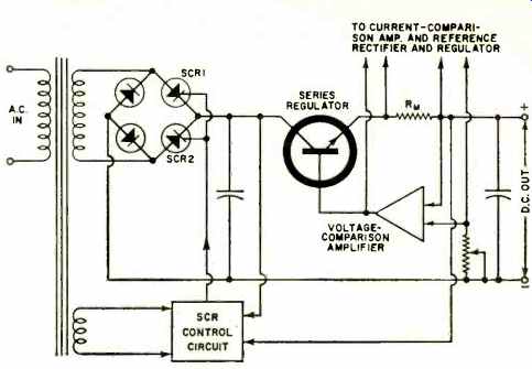
Fig. 4. Use of SCR preregulator with a CV /CC power supply.
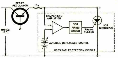
Fig. 5. Typical crowbar overvoltage protection circuit.
Most of the techniques described are circuit designs which come as an integral part of the power-supply package. Certain modifications can be made at the bench to achieve protection, but for critical applications and regular use, the power-supply buyer would do well to specify the protection he desires when he places his order.