By FOREST H. BELT
A survey of what is available to the service technician for checking leakage currents, amplification, and displaying characteristic curves of transistors, FET's, and diodes.


above: Various testers from B&K 162 ; Leader LTC -902 Williams AO,
etc.
THERE is certainly no mystique involved in testing transistors any more. Technicians and engineers know you can check for good or bad transistors with a simple ohmmeter, if the internal voltage or current is not too high. Lately, makers of volt-ohm-milli-ammeters have reduced ohmmeter voltages, and several have special low-power resistance ranges, so that they won't damage transistor or diode junctions.
But you might want to know if two transistors have the same beta, for use in push -pull. Or, you might want to pick one with low leakage for some critical circuit. There are a good many reasons you might need a quantitative evaluation.
That's when you need a transistor tester. There is a wide range of choices. Our recent survey for the accompanying chart turned up over twenty different models for the service technician; at least six are new this year. We know of two more that will be introduced soon.
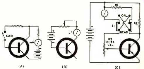
The testers available fall into five categories: (1) inexpensive type, (2) general type, (3) automatic type, (4) lab type, and (5) curve tracer (use with scope). Low Cost and Quick Even within this category, instruments vary considerably. The simplest model tests only /cop (collector-to-emitter leakage current with base open) and makes a beta test of sorts. The diagram of Fig. 1A shows the basic test setup that is used.
For this p-n-p transistor, negative voltage goes to collector and positive to emitter. That reverse-biases the collector and emitter junction. Any current that flows is IcEo leakage. A small-signal transistor should hardly wiggle a 0-3 mA meter at all. A power transistor could show normal IcEo up to quarter-scale. More than that means the transistor is defective--with excessive leakage or shorted. No reading means the transistor may be open.
To see if the transistor amplifies, you close the Gain switch. A resistor applies negative voltage to forward -bias the base-emitter junction. If the transistor is okay, collector current jumps upward. The meter should read considerably more than it did with the base open. If not, the transistor is faulty.
This kind of evaluation is "go /no -go" testing. You make no accurate gain measurement. Also, the test voltage for leakage may be much less (or more) than what's needed by the transistor you want to test. That creates some inaccuracies. Yet, at low cost, these testers are acceptable. Two models that work this way are the Heath IT -27 and the RCA WC -506A. The EMC212 makes a simple IcEO test and a check of d.c. beta. Then you can plug a transistor into the socket and test its performance as an oscillator. If it works, the signal generated can then be employed for signal-injection troubleshooting.
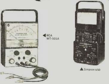
The Simpson 650 permits reasonably accurate d.c. beta readings. The 650 is an adapter that fits on the Simpson 260 v.o.m. Precision resistors, plus switches and adjustment pots, calibrate the tester for beta readings up to 250. The only leakage reading is /CEO. Testing /CEO instead of ICBO (collector -to -base leakage with emitter open) would be okay except that ICBO usually tells more about how well most transistors will operate. Acceptable /CEO and "relative gain" readings may camouflage a transistor that won't function well because of too much /Cap. Some testers omit the /CEO reading; their designers consider ICBO the more important test.
More Time, Accuracy, Cost
Several instruments test for both /ego and /CEO, and measure beta with somewhat more accuracy. We've labeled these "general"-type models. Some do other tests, too The Heath Model IT-18, for example, measures both kinds of leakage. The test for /ego of an n-p-n transistor is shown in Fig. 1B. (For a p -n -p the battery and meter are reversed.) The base -collector junction is reverse-biased.
Any current that flows is leakage. A few microamps is all that's allowable. As a rule of thumb: for r.f. transistors, no more than 5 µA; low-power transistors, no more than 50 µA; power-output transistors, up to 1 mA. The d.c. beta test in general-type instruments is simple, but it's calibrated so you get a better idea of how well a transistor can amplify. The test arrangement in Fig. IC is typical, although some may have several additional ranges and scales.
There are two steps. First, you push switch S1 to the Cal (calibrate) position. That puts the meter into the collector circuit across R2 and applies bias to the base through R1 and R3. You adjust bias with the knob of R3 until the meter reads a specific amount of collector current. For example, suppose this calibration Ic is 5 mA. As the second step you push S1 back to the Read position (labeled Beta on some instruments). R1 becomes part of the collector circuit. The meter switches to the base circuit.
The meter measures how much base current is flowing. If the scale is marked in microamps, you can figure out beta.
Roughly speaking, beta is the ratio of collector current to base current. Suppose that, with 5 mA of collector current, a particular transistor shows base current of 25 µA (0.025 mA). Collector current of 5 mA divided by base current of 0.025 mA equals beta of 200. To make it easier, the meter scale is marked in beta. This approximation of true a.c. beta is dependable only if the test voltages fit the particular transistor and its operating conditions.
Some instruments provide extra test ranges. The Heath IT-18 has two. So does the Lectrotech TT -250. The RCA WT -501A has five different operating levels for measuring beta; that improves the accuracy of the reading.
The Leader LTC-902 tests /CEO and two ranges of d.c. beta. It also generates a high-harmonic 1-kHz tone for signal injection. An internal amplifier, with gain of 90 dB, makes a good a.f. signal tracer. As in several instruments, metering functions are accessible separately: 0-50 mA and 0-20 volts, in this model. This and virtually all other units measure diode leakage.
Several instruments measure beta the a.c. way. The Sencore TF17 and TF151, the B&K 162, and the Eico 685 are examples in the general category. Several models in other categories also measure a.c. beta.
It's interesting to note that the B&K, Eico, and Sencore instruments also measure transconductance (GM) of field-effect transistors (FET's). That's similar in many ways to a.c. beta. GM of a FET is a ratio worked out by dividing signal current in the drain circuit by signal voltage at the gate.
The result is in mhos (reciprocal of ohms), or more accurately in micromhos (µmhos). You find a.c. beta in bipolar transistors by dividing collector signal current by base signal current. If you did it the complicated way, you'd figure out currents from voltages across resistors in the collector and base circuits (no ordinary instrument measures signal currents directly). Then you'd calculate beta. With a tester, you set up switches and controls and the meter shows you a.c. beta already calculated.

Fig. 1. (A) Basic test circuit for IcEO (collector-to-emitter leakage
current with base open), and -by closing the switch--a gain evaluation.
(B) Test for ICEO (collector-to-base leakage current with emitter open).
Reverse bias is used. Note that "n-p-n" transistor is shown
here while "p-n-p" is shown in (A). (C) The simple test for
d.c. beta requires two steps.
These B&K, Eico, and Sencore models are the "upper class" of general-type transistor testers. They all check leakage in both bipolar and field -effect transistors. The Sencore units measure only ICBO in bipolars, but measure both IGSS (gate-to-source leakage with drain shorted to source) and Inss (zero-bias drain current) in FET's.
The B&K 162 performs a whole gamut of bipolar and FET measurements. In addition to ICBO and ICEO tests, it measures collector-to-emitter leakage with the base shorted to emitter (ICES) This reading should be lower than the ICEO reading, but not as low as the kw) reading. The 162 also checks both IGSS and Inss in FET's.
The Eico 685 makes all three leakage tests for bipolars and both leakage tests on FET's. In addition, there is a pinchoff test for FET's. You apply 5 volts between drain and source, then turn up a control that applies pinchoff to the gate. When current stops, the voltage control knob tells you the pinchoff value. (You use the same variable voltage to determine where a zener diode breaks over or an SCR fires.)
Another general unit is the Sencore F1155. It's special in that it tests only FET's. The unit makes all the FET tests the other Sencore units make, plus gate -2 tests on dual-gate FET's.

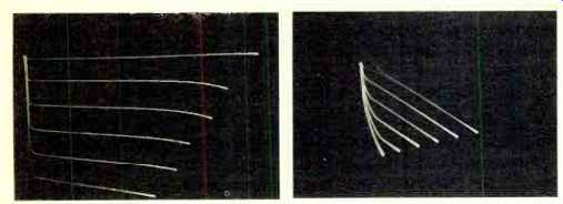
Fig. 2. Collector-voltage /current characteristics of transistor under
different biases are displayed simultaneously on scope screen by curve
tracer. (Left) Normal family of curves for an n-p-n transistor. (Right)
A "signature pattern" of a transistor that is being checked
out in a circuit.
Automatic Testing
A couple of operations to test a transistor -or three or four, if you count leakage tests -isn't much work. But the new Hy-Tronix tester, made by a division of Vanguard Tool Mfg. Co., takes even that chore out of in-circuit testing.
There are five colored lights on the meter scale.
The in-circuit test is quick. You flip the function switch for Visual or Sound indication, Xstr test. Then you make connections to the foil side of the printed board with a special probe. If the transistor is good, the two top lights or the two bottom lights start blinking. A label between the two blinking lights tell you the polarity of the transistor.
If there's a short or excess leakage, different lights start blinking. Labels between whichever lights blink will tell you which elements in the transistor are shorted.
If you set the Function switch for Sound, and the transistor is okay, a Sonalert beeper sounds off each time the "Good NPN" or "Good PNP" lights flash. If the transistor is bad, you hear nothing. The idea is that you can go through a bunch of transistors on a printed board without looking up from your work.
Out-of-circuit tests are similar to those by other testers.
You measure /CEO or /CEO. You can check beta with base current at 20 µA, 200 µA, or 2 mA, depending on whether the transistor is an r.f. type, low-power type, or a high-power type. The lights aren't involved.
"Lab" Testers
These instruments are for testing individual transistors, usually out-of-circuit. We've tagged them "lab types" because they provide operating conditions that closely approach optimum for each transistor -at least for some of the tests.
Simplest is the Heath IM-36. There are knobs for collector voltage, collector current, base voltage, base current, and leakage voltage. If you're testing transistors that need more voltage or current than the instrument supplies, you can connect an external voltage supply to binding posts on the panel. With the right combination of switch and control settings, you can test leakage between any two elements and measure d.c. beta under many different voltage and current conditions.
Similar advantages are obtained with the Hickok Model 890A. Test voltage and current for the collector are variable over a small range. You can test ICBO and measure a.c. beta with a 1-kHz oscillator (more realistic than a 60 -Hz a.c. beta test). You can test transistors in circuit or out.
The Hickok Model 870 is the most elaborate and versatile tester on the chart, and the most expensive. It has a roll chart with data on over 1000 transistors. If your cross-reference books are up to date, you can test new types too.
The 870 lets you test beta by a.c. or d.c. methods. The a.c. beta measurement is at 1 kHz, and transistor operating voltage and current are variable. You can test ICBO with a variable test voltage. You can run operating curves to determine saturation point, and check just about any other transistor parameter you care about. The instrument has voltages to suit almost any transistor--low power or high, ordinary or switching type.
Curve Tracers
These are fairly new to the transistor-testing scene, at least insofar as inexpensive instruments for the service technician are concerned. Only two curve tracers are available as this is written, but others are expected shortly.
There is some controversy about their usefulness for servicing. True, they are more elaborate than is necessary to spot a shorted or open transistor. But, for that matter, so are most transistor testers. Detractors object because you have to use an oscilloscope with the curve tracer -two pieces of equipment instead of one.
Many technicians insist transistors don't "get weak" like tubes do; they're either good or bad. Evidence proves otherwise for some kinds of transistors in some applications.
Heat changes operating curves; so does age in some instances. You can spot such variances only if you see whole operating curves.
A curve tracer and scope display a "family" of operating curves for the transistor being tested--see Fig. 2 (left). Each curve is the Ic-Vc characteristic of the transistor. It is made by "sweeping" the collector voltage while keeping a certain value of base current (bias). The family of curves is developed by stairstep changes of bias. Each change of bias makes another curve. A different family can be displayed if you change the average (center) collector voltage. In an elaborate curve tracer, then, you can pick whatever collector "center" voltage and whatever set of bias stairsteps suit a particular transistor.
The Eico 443 lets you measure beta, IcBO, inverse breakdown voltage, and several other parameters. You must know the calibration of your scope, but the 443 has calibration voltages built in. A collector -current switch lets you display two families of three curves each: one family for signal transistors and another for power types.
The Williams Model A provides for testing at eight different collector "center" voltages. The increment between stair-steps of base current is also variable. You can set the switch to make the curves 10 µA, 20 µA, 50 µA, 100 µA, 200 µA, 500 µA, or 1 mA apart. You can learn to read beta, spot leakage, test for breakdown levels, and so on. You must calibrate your scope, but that isn't too hard to do; most scopes have their own calibration system built right in.
Once a typical family of curves is available for every transistor type, the instrument will be more useful. It can also be used for SCR's, zener diodes, FET's, and ordinary diodes. But you must become familiar with what patterns are normal.
One TV manufacturer, Sylvania, has begun adding in-circuit "signature patterns" to service data for transistors in TV receivers. An example is shown in Fig. 2 (right). Once setmakers or service-lit publishers add transistor curve data to schematics, the curve tracer can be a more valuable aid.
You just go through the set (with power off) touching the special three-prong probe to each transistor at the foil connections. Compare the curves you get with the pattern specified for that transistor in that circuit, and you can spot any significant variations.
The special transistor-testing probe we've mentioned is a product originated by B&K. The Model FP-3 probe has three tips or prods of needle -point steel. Each prod is independently mounted in a spring-loaded ball-socket. And they're made in unequal lengths. The longest is for the collector connection, the middle length for emitter, and the shortest for base.
Here's how you use the probe. Locate the E, C, and B connections on the foil side of the printed board. Push the needle tip of the collector prod into the C connection.
Then, keeping pressure so that the tip doesn't slip off, rotate the body of the probe until the emitter tip is over the E connection; push downward until it makes contact. Keeping that pressure applied, again move the probe body around until the base tip is over its connection. Push downward some more and all three connections are made -even through resin protection -and with one hand.
You can use the probe with just about any tester listed in the chart. It is included with the B&K 162 and the Williams curve tracer.
(adapted from: Electronics World magazine; Jul. 1975)
================