By JAMES E. McALISTER
An aid to designers and experimenters who must fabricate their own coils. Chart is applicable to both hand-wound and pre wound coil stock.
THE inductance of a single-layer air-core coil can be expressed by the well-known formula:
L = (n^2r^2) /(9r + 10l)
where: r is coil radius in inches, n is total number of coil turns, l is total coil length in inches, and L is coil inductance in microhenrys. This formula becomes more potent if the winding pitch N in turns per inch is used in place of total turns (n = Nl). This substitution, for example, will allow quick inductance calculations to be performed for pre-wound coil stock of fixed pitch and radius. The problem is then simply one of choosing the proper length of stock to give the proper inductance.
Similarly, hand-wound coils can be designed by selecting an appropriate pitch and radius and, as before, solving for the proper coil length. Since pitch and radius are often chosen by trial and error, several calculations may sometimes be required before a realistic coil length is obtained. For this reason, a nomogram can be usefully employed to allow quick convergence on a meaningful design.
Problem: Choose the proper length of coil stock of 1/2-inch radius and 4 turns per inch to give an inductance of 0.5 uH.
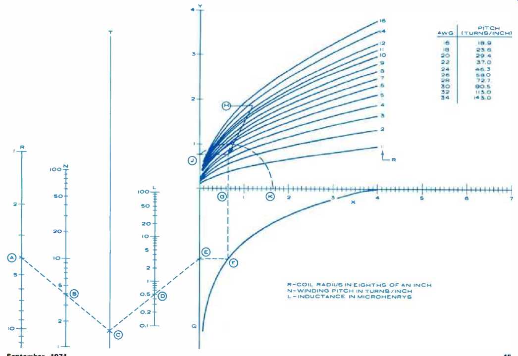
In this case, the radius is fixed at 1/2 inch. This value should be located on the R scale of the nomogram. Note that values of R are expressed in eighths of an inch, so the value of R chosen is 4 (point A). Next, the winding pitch of 4 turns per inch should be found on the N scale (B). A line is drawn connecting these two points and is extended to intercept the T scale (C). From C, another line is drawn through 0.5 (the required inductance) on the L scale (D) and is extended to cross the Q scale (E). From E, a horizontal line is projected to intercept the graph at F. A vertical line is then drawn to cross the X-axis at G and on to cross the appropriate R line (the radius R is expressed in eighths of an inch here, too) at (H). A horizontal line is drawn through H to intersect the Y-axis at J. With a pair of dividers or a compass, an arc is drawn from J (with G as the center) to the X-axis (K). The value of X at K (in this case, 1.65) is the length in inches of the coil stock required to give the desired inductance.
Actual calculation of the coil inductance using the length of 1.65 inches gives 0.52 uH, rather than 0.5 pH. This represents an error of only 4 %, which is certainly within reason. It should also be noted that the original formula is accurate within 1% whenever coil length is greater than or equal to eight-tenths of the radius.
If the coil is being wound by hand with a length of 1.65 and a pitch of 4, it may be advantageous to wind 6.6 turns evenly in 1.65 inches of length. The pitch will then automatically be the necessary 4 turns per inch.
The pitch of close-wound coils is approximately the reciprocal of the wire diameter. Approximate pitches for common wire sizes are tabulated below for enameled, solid copper wire. Data for other types of insulations and wire sizes may be found in a rather complete table in The Radio Amateur's Handbook" (ARRL).
.
======
Automatic Railroad-Car Identification
======
(adapted from: Electronics World magazine; Jul. 1975)
================