(source: Electronics World, Dec. 1971)
By DAVID L. HEISERMAN
Operating principles and performance of a number of economical systems that can transmit graphic material over conventional telephone circuits.
A GADGET beloved by science-fiction writers is an "instant home newspaper." A future-day hero presses a button and a newspaper immediately emerges from a slot in the wall. Today, instant communication of printed information is a reality in the business world.
Facsimile is the key to instantaneous communication of printed matter. For decades, facsimile has been closely associated with the transmission of pictures over leased lines or radio waves.
Today's facsimile revolution, however, encompasses all forms of printed material as well as pictures and the communications medium is an ordinary telephone line.
Why didn't the facsimile revolution gather impetus before now? Because the communications links between a facsimile transmitter and receiver were far too expensive. Until 1968, AT&T prevented anyone else from using its commercial telephone lines.
This meant facsimile stations had to be linked together with either expensive cross-country lines or elaborate radio equipment. When a 1968 court decision forced AT&T to open its lines for acoustical data transmission, several enterprising communications firms began developing low-cost, telephone linked facsimile systems. Using ordinary telephone lines wipes out the expense involved in cross-country lines and radio gear. The quality of reproduction presently suffers somewhat from the narrow bandwidth imposed by voice-grade lines. But the facsimile people have an eye on a vast new market that doesn't demand exceptionally high-quality reproductions--the entire business world and, perhaps eventually, every home in America.
Marketing and Development
One of the biggest selling points for low-cost, telephone-linked facsimile systems is that they can replace a teletypewriter. Businessmen who never thought they could make a teletypewriter pay for itself are leasing facsimile systems for sending messages and graphics. Compared to a teletypewriter, the new facsimile systems are easier to operate, less expensive, and much faster for long messages.
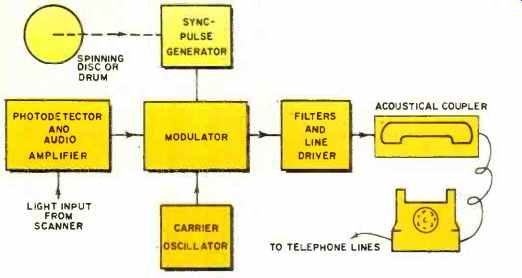
Fig.1. Simplified block diagram of the transmitter section.
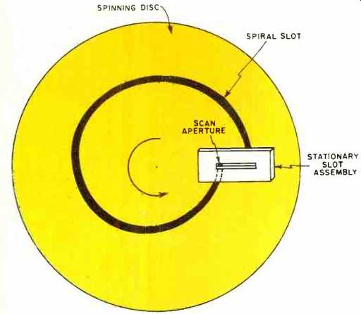
Fig. 2. The spinning disc scanning assembly. As the disc spins counterclockwise,
the scan aperture appears to sweep rapidly across the stationary slot
from left to right. Since the document moves vertically on one side of
the assembly, the stationary photodetector on the other side sees a raster
scanned version of the document that is being transmitted.
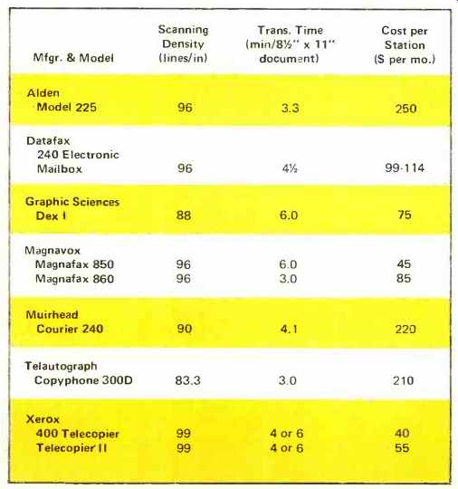
Table 1. Summary of important characteristics of a number of facsimile
units suitable for operation over the telephone lines.
The major development work in the telephone-linked facsimile industry now concerns increasing resolution while lowering transmission time and cost. Present-day systems have to trade off one or two of these factors to optimize another. See Table 1.
As promising and, .indeed, as successful as the modern facsimile business already is, the manufacturers involved are retarding-their own progress by an unwillingness to get together on operational standards. Apparently the companies are all edgy about stumbling over the other fellows' patents. As a result of their lack of cooperation, no two companies produce compatible facsimile systems. Until they get together to set up some workable standards, we cannot expect this facsimile revolution to erupt into the technological explosion it promises to be.
Telephone Facsimile Transmitters
The job of the facsimile transmitter is to transform printed information on a document into electrical signals suitable for transmission over standard voice-grade telephone lines. This process generally involves five steps: (1) scanning the document to produce electrical analog signals representing the information printed on it, (2) generating a set of scan and sync signals, (3) modulating the scan and sync signals with an audio carrier signal, (4) conditioning the composite facsimile signal with a set of sideband and noise filters, and (5) coupling the composite signal to a telephone handset via an acoustical-coupler unit. See Fig. 1.
Portable or low-cost facsimile transmitters use one of two kinds of mechanical scanning systems: a spinning disc or a spinning drum. In either case, the idea is to combine mechanical motions, optical devices, and electronic circuitry to produce line-by-line electrical analogs of information printed on a document.
The spinning disc system (Fig. 2) uses a lens to focus a brightly illuminated image of the document onto the disc.
The disc has a spiral slot cut through it, so only a small portion of the image passes through. A stationary slot behind the spinning disc reduces the transmitted portion of the light to a small dot that appears to scan the document horizontally. Another motor pulls the document itself in a vertical direction. A set of gears synchronize the motion of the disc and document drive so that each revolution of the disc results in a small advance of the document.
The spot of light from the disc and slot assembly falls onto a photodetector-often a photomultiplier tube. This device changes the brightness information in the spot of light into analog voltage signals, thus completing the first phase of the facsimile-transmission process.
There are two versions of the spinning drum mechanical scanner. In one version, the document moves on the slower scan axis while the optical devices spin rapidly on the drum.
The other version works just the other way around-the document spins rapidly while the optical devices scan slowly. Both versions accomplish the same kind of scanning task; and, like the spinning-disc scanners, they combine a light source, lenses and mirrors, and a photodetector to finish the job.
Just as in a TV system, the scanning operations in a facsimile transmitter and receiver must be carefully synchronized. The facsimile transmitter has a sync-pulse generator coupled to the spinning disc or drum. The generator produces sync pulses for a few seconds before the document data begins to flow and, of course, during the entire data transmission time.
The spinning-disc scanner generally produces the sync pulses optically. The spiral slot is cut so that no light can pass through it during the last 10° of each revolution. The photodetector interprets this as a "blacker-than-black" sync pulse signal. A spinning-drum scanner, on the other hand, often has a switch or the shaft of a small generator mechanically coupled to the revolving drum. As the drum turns, the switch or generator produces electrical synchronizing pulses.
The scan signals and sync pulses come together in the acoustical modulator circuit. Most telephone-linked facsimile systems use FM modulation. The center frequencies are normally around 1700 Hz, with 1300 Hz and 2100 Hz representing "black" and "white" frequency limits. Manufacturers who selected FM modulation believe their problems of wide bandwidth, phase shift, and frequency distortion are minor compared to signal fading and noise problems associated with acoustical AM transmission.
Two manufacturers, Graphic Sciences and Telautograph, have chosen the AM route, however. The receivers in these facsimile systems have an a.g.c. circuit keyed to the sync pulse amplitude. By adjusting the gain of the input amplifier circuits, the a.g.c. system compensates for any signal fading. The systems overcome environmental noise introduced at the telephone handset by means of carefully soundproofed coupling assemblies, and they eliminate most telephone line noise with a set of highly selective filters.
Many potential telephone facsimile users are skeptical of AM transmission. Perhaps this skepticism is based on misapplication of a bit of common knowledge-FM radio is less noisy and has better fidelity than AM radio. Spokesmen for Graphic Sciences are quick to point out that radio and voice-grade telephone transmission are two entirely different media, and that the problems and advantages of one medium do not necessarily carry over to the other. The facsimile manufacturers who have decided to use AM transmission believe it is easier to solve the problems of AM acoustical transmission.
Graphic Sciences also likes to stress another big advantage of AM transmission-narrow bandwidth. They say: "Because FM uses all frequencies, there is no ability to exchange control signals between the transmitter and receiver. Thus, FM receiving units are slave units to the transmitter. FM precludes the use of control signals to automatically halt both transmitter and receiver simultaneously from the receiving end. Thus the receiving party is helpless to halt transmission in the event that a paper jam or other failure occurs." The AM facsimile transmitters use carrier frequencies on the order of 2 kHz, while the scan signals to the modulator contain frequency components in the 0 to 1-kHz range. Using an upper-sideband filter, the frequencies actually carried by the telephone lines range between 1 kHz and 2 kHz-a bandwidth only one-fourth that of a comparable FM system. Thus, additional data frequencies remain available for high-speed transmission and future developments.
Telephone Facsimile Recorders
The job of the recorder portion of a facsimile system is to translate the composite facsimile signal from the telephone lines into a document that very nearly resembles the one running through the transmitter. The main processes involved in facsimile recording are: (1) demodulating the composite facsimile signal, (2) synchronizing the recorder scanning mechanism with that of the transmitter, and (3) reproducing the information on a piece of paper. See Fig. 3.
Unless a facsimile recorder has an optional automatic answering feature, the recording process begins when a human operator answers the telephone, listens for a signal tone, and places the handset into an acoustical-coupling unit. (The Datafax 240, for example, features automatic answering, automatic disconnect, and can be equipped with an optional document loader attachment if desired.) The acoustical coupler passes the signal to a set of line noise filters and, if the recorder is of the AM type, an a.g.c. amplifier adjusts the signal to a predetermined level. After these initial steps, another circuit demodulates the composite signal, sending the sync pulses to a pulse-coincidence circuit and the analog-data signals to the writing mechanism.
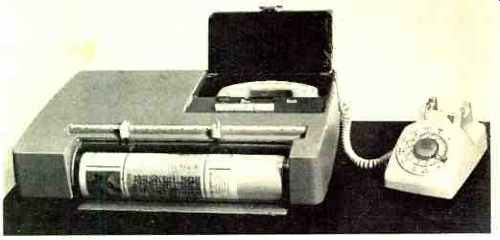
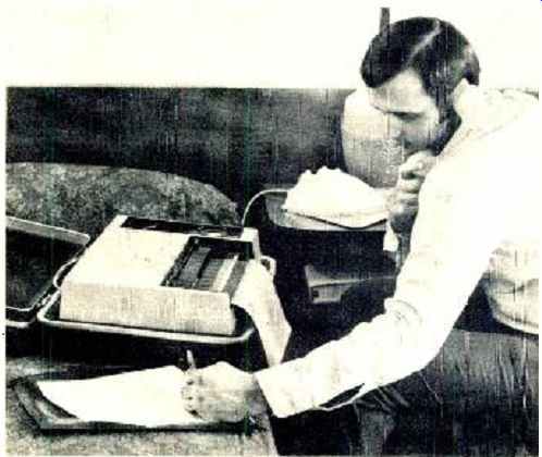
------- This small, economical transceiver by Graphic Sciences is
example of the new breed of facsimile equipment described.
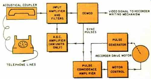
Fig. 3. Block diagram of recorder or receiver section of system.
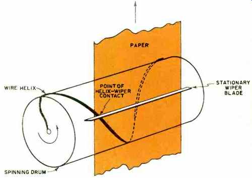
Fig. 4. The "lawnmower" writing mechanism. As the drum spins
counterclockwise, the point of contact between the wire helix and the
stationary wiper blade sweeps from left to right. Electrosensitive recording
paper, moving upward between helix and wiper blade, darkens in response
to current flow between helix and blade.
Each of today's low-cost, telephone linked facsimile systems uses one of three different kinds of recording paper and writing mechanisms: a wet electrolytic paper and a "lawnmower" writing drum; a dry electro sensitive paper and a thermoelectric scribe; or a combination of white paper and carbon paper used with a vibrating impact head.
Recorders that use the wet electrolytic paper pass the paper between a rapidly spinning drum and a stationary metal wiper. Fig. 4. The drum has a single turn of wire twisted around it in a helical fashion. The metal wiper, fixed parallel to the long axis of the drum, presses the paper against the wire at only one small point. As the "lawnmower" spins, the point of contact moves horizontally across the paper. Each revolution corresponds to one horizontal scan.
If the "lawnmower" is properly synchronized with the scanning mechanism at the transmitter, then the helix and wiper arm are in contact at the left-hand edge of the paper at the very instant the transmitter begins a new scan at the left-hand edge of the original document.
The wet electrolytic paper is saturated with a clear fluid that darkens in response to a current flowing through it.
The amount of darkening is proportional to the amount of current. By applying the demodulated facsimile signal between the helix and wiper arm, the moving point of contact intensity-modulates the darkness of the scan lines on the paper.
Wet electrolytic papers must be kept moist until just after the writing process. To make the process as simple and clean as possible for the operator, the paper unwinds from a long roll stored in a chamber designed to keep the electrolyte from drying out. After passing through the writing mechanism, the paper passes over a heating element that dries it for more convenient handling. Since the paper comes in long rolls, it must be cut at the end of every page or transmission. This is generally done by means of a cutting blade actuated by a signal from the transmitter.
Long rolls of paper, humidity controlled storage chambers, drying elements, and cutting blades all contribute to the size, weight, complexity, and cost of a facsimile receiver unit. The Graphic Sciences Dex I and the Xerox 400 Telecopier, both small economical transceiver units, bypass all these disadvantages by using a dry-paper recording technique.
Dry electro sensitive facsimile paper comes in standard 8 1/2" X 11" sheets. During manufacture, the writing side of the paper is first covered with black ink, then coated with a thin layer of white zinc oxide powder. Scratching the writing side of the paper reveals the black undercoating. Facsimile recorders, however, generally expose the black undercoating by burning away the oxide with a small electric current.
Since dry facsimile paper comes in relatively small sheets instead of long rolls, it is possible to further simplify the recording mechanism by spinning the paper rapidly and letting the more complicated writing assembly move along the slower scan axis. The paper, then, spins on a high-speed metal drum--each revolution corresponding to one horizontal scan at the transmitter. The writing assembly is simply a piece of fine wire attached to a slow-moving worm gear. The wire brushes against the paper very lightly, passing facsimile signal current through the paper to the metal drum. The more intense the current flow at a given point in a scan, the darker the resulting spot on the paper.
The carbon paper impact writing technique also has the advantage of being a dry recording process. the disadvantage is that it requires two separate rolls of paper-one roll of ordinary white paper and a roll of carbon paper. A drive motor pulls the two papers together through the writing mechanism. The writing mechanism in this case is a pointed impact head that rapidly scans the papers horizontally and, at the same time, vibrates against them with a frequency determined by the incoming facsimile signal. With each impact, the head transfers a bit of ink from the carbon paper onto the white paper. The higher the frequency of impact, the darker the line on the paper.
Perhaps the most standardized part of all telephone linked facsimile systems is the scan synchronizing sub-systems. Taking advantage of the fact that power-line frequencies are very nearly the same all over the nation, the facsimile systems all use synchronous motors to drive the scanning assemblies. The only real discrepancy that can occur between a set of widely separated synchronous motors is a phase difference. In the case of the slower scan axis (generally the vertical axis), the phase differences aren't relevant at all and the slight frequency differences, if any, don't add up to any significant amount of vertical distortion. Phase differences in the horizontal scan, however, can produce an effect similar to loss of horizontal sync on a TV receiver.
To bring the facsimile receiver's horizontal drive motor into phase, the transmitter sends out a stream of sync signals before sending any video data. Early lab studies showed that the receiver motor could be forced into phase within several seconds, and that there was no need for an in-phase feedback signal from the receiver unit. To prevent a possible loss of sync during a long transmission, however, the transmitter continues to send out horizontal sync pulses as a "blacker-than-black" portion of the acoustical video signal. A pulse coincidence circuit in the receiver compares the phase of the receiver's drive motor with the incoming sync pulses. Whenever any such discrepancy occurs, the circuit immediately sends the drive motor the proper corrective signal.
-------------
Alden Electronic & Impulse Recording Equipment Co., Inc.
Westboro, Massachusetts 01581 Datafax Corp.
Div. Stewart-Warner Corp.
1300 N. Kostner Avenue Chicago, Illinois 60651
Graphic Sciences, Inc.
Corporate Drive, Commerce Park Danbury, Connecticut 06810 Magnavox Systems, Inc.
1505 E. Main Street Urbana, Illinois 61801
Muirhead Instruments, Inc.
1101 Bristol Road Mountainside, New Jersey 07092
Telautograph Corporation 8700 Bellanca Avenue Los Angeles, California 90045
Xerox Corporation Business Products Group Rochester, New York 14603
Table 2. Listing of companies marketing inexpensive systems.
--------------
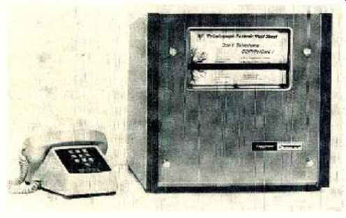
--- Telautograph's transmitter receiver units are typical of the larger
telephone-linked facsimile systems. The acoustical coupling unit for the
telephone is not shown in this photo.
--- The Xerox 400 Telacopier is portable facsimile transceiver that can
link a salesman on the road with his home office.