The high input impedance and high gain of the FET promote simplicity and efficiency in many transistorized oscillator circuits. Frequently, the FET may be used directly in tube-type circuits and requires no special circuit components. This latter convenience is important, especially in crystal-controlled, r-c-tuned, and capacitance-feedback oscillators.
Negligible loading of l-c-tuned circuits by the FET may result in higher output and lower distortion than is usually obtained with comparable bipolar transistors. This desirable characteristic also removes the need to tap coils for transistor impedance matching, and tends to preserve undisturbed the Q of the tank circuit. The high gain obtainable with many FET's ensures that sufficient output voltage will be available for efficient feedback.
FET's are proving to be useful in oscillators of all types. They can be used across the frequency-spectrum-from low audio frequencies to high radio frequencies. The oscillator output can be a symmetrical sinusoidal waveform or a nonsinusoidal train of pulses.
TRANSFORMER-FEEDBACK A-F OSCILLATOR
Fig. 1 shows the circuit of an audio-frequency oscillator which uses inductance-capacitance tuning and inductive feedback and em ploys one 2N2608 P-channel FET. This simple arrangement is useful for general-purpose, single-frequency applications, such as bridge excitation, tone signaling, signal injection and tracing, and amplifier testing.
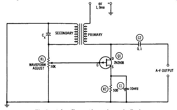
Fig. 1. A-f oscillator with transformer feedback.
Feedback from the drain (output) circuit to the gate (input) circuit is provided by an interstage audio transformer, T1, which sup plies a 2: 1 ( or higher) step-up turns ratio between primary and secondary windings. This transformer must be polarized correctly for regenerative feedback, by proper connection of the primary and secondary.
The oscillation frequency is determined by capacitance Cx and the inductance of the transformer secondary:
f= 1/2 pi __/LC
where, f is the oscillation frequency, in hertz, L is the inductance of the transformer secondary, in henrys, C is the capacitance of Cx, in farads.
Since transformer manufacturers do not usually specify the inductance of windings, this value must be measured-or various capacitors may be tried as C, until the desired frequency is obtained.
Because of the self-capacitance of the secondary, oscillation will occur at one frequency when no external capacitor is in the circuit.
and this is the highest frequency at which the circuit will operate.
The feedback amplitude is adjusted with potentiometer R1. The latter must be set for best sine-wave output shown by an oscilloscope connected to the A-F OUTPUT terminals. Excessive feed back overdrives the FET and clips the output-wave peaks; insufficient feedback causes instability and sluggish starting.
A U.T.C. Type S-8 transformer tested in this circuit gave a frequency of 500 Hz with Cx = .002 mfd, and 1100 Hz with no external capacitor. The open-circuit output voltage was 1 volt rms at 500 Hz, and the current drain 1 ma at 6 vdc. Comparable operation is possible with some of the smaller, transistor-type transformers.
Since the output is capacitance coupled from the drain circuit which includes transformer T1, the external load will tend to de tune the oscillator somewhat. This effect can be eliminated, however, by adding a source follower ( see Section 2) to isolate the oscillator from the load.
The gate electrode of the 2N2608 is internally connected to the metal case of this FET, so care must be taken in the mounting of the FET to avoid contact between the case and other components or wiring. Resistor R2 is 1/2 watt, and electrolytic capacitor C1 is rated at25 dcwv.
L-C-TUNED A-F OSCILLATOR
In the oscillator circuit shown in Fig. 2, the frequency is determined by capacitance Cx and the inductance of iron-cored inductor L1: 1 f= 2 pi ../LC where, f is the frequency of oscillation, in hertz, L is the inductance of L1, in henrys, C is the capacitance of Cx, in farads.
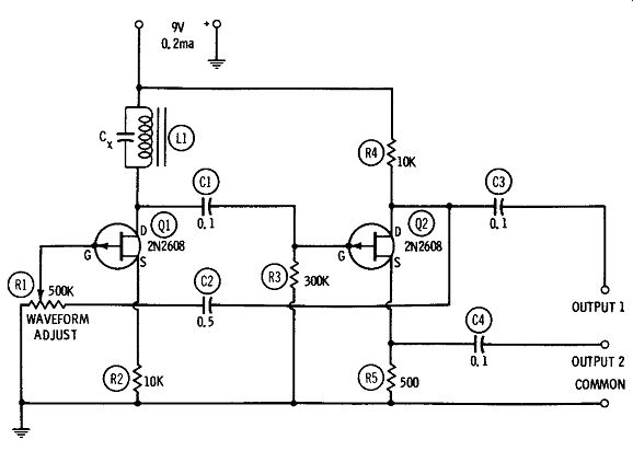
Fig. 2. L-C-tuned a-f oscillator.
Here, L may be any convenient coil ( from a filter choke to a high-Q adjustable inductor), and Cx may be selected to give a desired frequency. The experimenter may start with a given coil and choose a capacitor. or start with a given capacitor and choose an inductor.
The circuit is essentially a 2-stage r-c-coupled amplifier, employing 2N2608 FET's, with the tuned circuit (LCx) forming the plate tank of the first stage, and with overall feedback for oscillation provided by capacitor C2. An even number of stages is necessary for the required positive feedback.
Potentiometer R1 allows the feedback amplitude to be adjusted for best sine-wave output, as observed with an oscilloscope connected to the output terminals ( either OUTPUT 1 or OUTPUT 2). Excessive feedback overdrives Q1 and distorts the output wave; in sufficient feedback causes instability and sluggish starting.
With L1 = 5 hy and Cx = .005 mfd, the frequency is 1000 Hz.
The open-circuit signal voltage at OUTPUT 1 (high-impedance output) is 1 volt rms, and at OUTPUT 2 (low-impedance output) is 0.6 volt rms. Current drain is 0.2 ma at 9 vdc.
All wiring must be kept short, direct, and rigid for maximum stability and minimum stray pickup, and the entire device should be box shielded. The gate electrode of the 2N2608 is internally connected to the metal case of this FET, so care should be taken to avoid contact between the FET's and other components. Fixed resistors R2, R3, R4, and R5 are 1/2 watt.
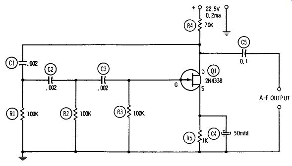
Fig. 3. Phase-shift a-f oscillator.
PHASE-SHIFT A-F OSCILLATOR
The phase-shift oscillator is well known for its excellent sine-wave output and the simplicity and compactness of the resistance-capacitance network which determines its frequency. Fig. 3 shows an FET version of this familiar circuit, employing a single 2N4338.
The frequency-determining r-c network consists of identical capacitors C1, C2, and C3, and identical resistors R1, R2, and R3.
Each leg of this network ( i.e., C1- R1, C2-R2, and C3-R3) produces a 60-degree phase shift. The total 180-degree phase shift thus introduced in the feedback path from drain to gate of the 2N4338 is correct for the positive feedback needed for oscillation. Oscillation occurs at that frequency at which the phase angle of each leg of the network is 60 degrees: 1 f = 10.88 RC where, f is the frequency of oscillation, in hertz, R is the resistance of R1, R2, or R3, in ohms, C is the capacitance of C1, C2, or C3, in farads.
From this relationship, C = 1/ ( 10.88fR) and R = 1/ ( 10.88fC). All capacitors and resistors must be rated at 1 percent or better accuracy.
The network values given in Fig. 3 ( C1 = C2 = C3 = .002 mfd, and R1 = R2 = R3 = 100,000 ohms) give a signal frequency of approximately 460 Hz. The open-circuit output voltage of the circuit at this frequency is 8 volts rms. Current drain is 0.2 ma at 22.5 vdc.
In this single-stage circuit, the FET must be a strong amplifier ( i.e., its transconductance must be high), or no oscillation will be obtained. Specifically, the voltage amplification of the circuit must be high enough to override the insertion loss of the r-c network; otherwise, the feedback voltage reaching the gate will be insufficient to set up oscillation.
As in other simple oscillators, the output here is capacitance coupled from the drain circuit which includes the input end of the phase-shift network. Because of this, the external load may tend to detune the oscillator somewhat. This defect may be corrected, however, by adding a source follower ( see Section 2) to isolate the oscillator from the load.
All wiring must be kept short, rigid, and direct for maximum stability and minimum stray pickup. However, complete shielding is unnecessary unless the oscillator is operated in an environment of strong magnetic fields. But care must be taken to mount the 2N4338 clear of other components and wiring, as the gate electrode is internally connected to the metal case of this FET and is vulnerable to capacitive pickup, as well as to short circuits and grounds.
All resistors are 1/2 watt, and electrolytic capacitor C4 is rated at 25 dcwv.
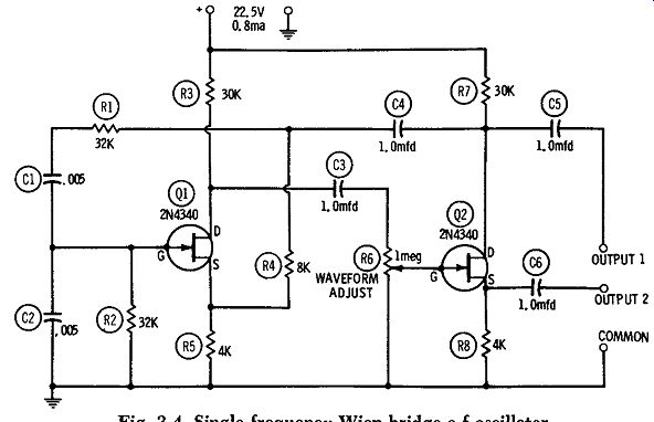
Fig. 4. Single-frequency Wien-bridge a-f oscillator.
SINGLE-FREQUENCY WIEN-BRIDGE A-F OSCILLATOR
Another widely used r-c-tuned audio oscillator is the Wien bridge type. This circuit is somewhat simpler than the phase-shift oscillator described in the preceding section, since the Wien bridge uses only two resistors and two capacitors to set the frequency, whereas the phase-shift oscillator requires three capacitors and three resistors. However, the Wien-bridge circuit requires two FET's.
Fig. 4 shows a Wien-bridge oscillator circuit arranged for single-frequency audio operation. This circuit, employing two 2N4340 FET's ( Q1, Q2), is essentially a 2-stage r-c-coupled amplifier with a Wien bridge ( C1, C2, R1, R2, operated against R4, R5)
connected in the feedback path from the output drain ( Q2) to the input gate ( Q1). In this frequency-determining r-c network, C1 = C2, and R1 = R2. At one frequency, determined by these R and C values, the feedback voltage at the Q1 gate is in the proper phase for oscillation, and at all other frequencies degeneration produced by the feedback-voltage drop across R4 + R5 cancels oscillation.
The output of the Wien-bridge oscillator therefore has an excellent sinusoidal waveform. When C1 = C2, and R1 = R2, f = 21rRC 1 where, f is the oscillation frequency, in hertz, R is the resistance of R1, in ohms, C is the capacitance of C1, in farads.
From this relationship, C1 = 1/ ( 2 pi fR), and R1 = 1/ ( 2 pi fC). The C1, C2, R1, and R2 values given in Fig. 4 are correct for 1000-Hz operation. Excellent sine-wave output is obtained at this frequency when potentiometer R6 is set for the best waveform observed with an oscilloscope connected to the OUTPUT 1 and COMMON terminals. The no-load output is 6 volts rms at the OUTPUT 1 (high-impedance) terminal, and 0.4 volt rms at the OUTPUT 2 (low-impedance) terminal. Current drain is 0.8 ma at 22.5 vdc.
For maximum stability and minimum stray pickup, all wiring must be kept short, rigid, and direct. And since the gate electrode of the 2N4340 is internally connected to the metal case of this FET, both transistors must be mounted clear of other components. All fixed resistors are 1/2 watt. Since the high output is capacitance coupled from the Q2 drain circuit which is also coupled to the Wien bridge network through capacitor C4, the output load may tend to detune the oscillator somewhat. However, this defect may he corrected, as recommended for the phase-shift oscillator, by adding a source follower ( see Section 2) to isolate the oscillator from the load.
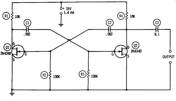
Fig. 5. Drain-coupled multivibrator.
DRAIN-COUPLED MULTIVIBRATOR
Fig. 5 shows the circuit of a free-running multivibrator, based on two 2N4340 FET's ( Q1, Q2). This arrangement is equivalent to the plate-coupled, tube-type multivibrator.
The multivibrator is essentially an r-c--coupled amplifier with the output of each of two stages driving the input of the other. Thus, in Fig. 5 the drain of Q1 is coupled through capacitor C1 to the gate of Q2, and the drain of Q2 is coupled through capacitor C2 back to the gate of Q1.
As in the tube circuit, the generated frequency is governed by the time constants of the cross-coupled r-c legs: where capacitances are in farads and resistances in ohms. If the components are closely matched ( i.e., C1 = C2, and R2 = R3), the formula becomes simply
f = 1 2 C2R2
The coupling resistance and capacitance values in Fig. 5 give 2500-Hz operation. Some adjustment of these values may be required with individual FET's.
The output signal is a rectangular wave having a no-load amplitude of 12 volts peak to peak when a 15-volt d-c supply is used.
Current drain is 1.4 ma. A synchronizing signal may be injected at either gate or either drain.
Resistors R2 and R3 must match within 1 percent or better, and so must capacitors C1 and C2. All resistors are 1/2 watt. Wiring should be kept short and rigid, but lead dress is not critical except at frequencies of 5 kHz and higher. The 2N4340's should be in stalled out of contact with each other or with other components, since the gate electrode is internally connected to the metal case in this FET.
SOURCE-COUPLED MULTIVIBRATOR
A somewhat simpler free-running multivibrator circuit than the one described in the preceding section is shown in Fig. 6. This source-coupled multivibrator is equivalent to the cathode-coupled, tube-type circuit. In this arrangement, using two 2N4340 FETs ( Q1, Q2), only one interstage coupling capacitor ( C1 in the for ward path from Q1 to Q2) is needed. The coupling back from the second FET (Q2) to the first ( Q1) is obtained through the common source resistor, R3.
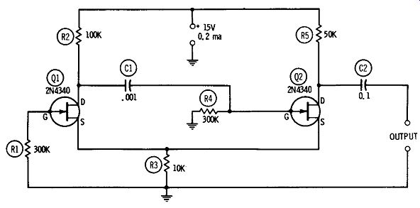
Fig. 6. Source-coupled multivibrator.
The generated frequency depends principally upon capacitance C1 and resistance R4. The C1 and R4 values shown in Fig. 6 are for 550-Hz operation. Increase C1 for lower frequencies, and de crease it for higher frequencies. The output is a rectangular wave with an amplitude of 10.5 volts peak to peak when the d-c supply is 0.2 ma at 15 volts de. A synchronizing voltage may be injected at the gate of Q1.
All resistors are 1/2 watt. As in the previous circuit, wiring should be kept short and rigid, but lead dress is not critical except at frequencies of 5 kHz and higher. The 2N4340's must be installed free from contact with each other or with other components, since the gate electrode is internally connected to the metal case in this FET.
SELF-EXCITED R-F OSCILLATOR
The 2N3823 FET has an excellent high-frequency figure of merit ( ratio of transconductance to input capacitance), hence is useful for r-f applications through the vhf region. Fig. 7 shows the circuit of a self-excited radio-frequency oscillator employing this FET. This is a series-fed Hartley circuit, in which the tank circuit L1 C1 determines the generated frequency. The values of C1 and L1 may be determined for a desired frequency, either in terms of an available capacitance or available inductance:
C, = -1 /39.5 L1 f2
where,
1 Li= 39.5 PC C1 is capacitance, in microfarads, L1 is inductance, in microhenries, f is frequency, in megahertz.
The inductance and capacitance values may also be found with the aid of a reactance slide rule or 1-c-f chart. For variable-frequency operation, either C1 or L1 may be adjustable. The coil is center tapped, but in some instances the tap may have to be displaced somewhat from center.
Radio-frequency output may be capacitance coupled from the drain, as shown in Fig. 7. In this case, the no-load r-f output amplitude is 2.5 volts rms when the d-c input is 5.3 ma at 6 vdc.
Link coupling out of L1 also may be employed-the conventional manner. The r-f potential across L1 is 1.3 volts peak.
All wiring must be kept short, direct, and rigid, especially at frequencies above 1 MHz. The case of the 2N3823 is connected to a fourth pigtail which should be grounded, as shown. All resistors are 1/2 watt.
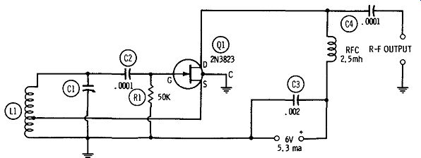
Fig. 7. Self-excited r-f oscillator.
CONVENTIONAL CRYSTAL OSCILLATOR
Fig. 8 shows the circuit of a crystal-controlled r-f oscillator employing a 2N3823 FET. This circuit is equivalent to the conventional plate-tuned, tube-type circuit and is operated in the same way as the latter.
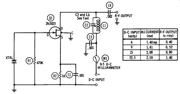
Fig. 8. Conventional crystal oscillator.
In this arrangement, capacitance C2 and inductance L1 are chosen to resonate at the crystal frequency. These tank-circuit values may be determined for a desired frequency either in terms of an avail able capacitance or available inductance: where,
C2=1/[39.5 f^2 L1]
L1=1/[39.5 f^2 C2]
C2 is capacitance, in microfarads,
L1 is inductance, in microhenries,
f is frequency, in megahertz.
The inductance and capacitance values may be determined also with the aid of a reactance slide rule or 1-c-f chart. Either C2 or L1, or both, may be adjustable. The circuit is set to the crystal frequency in the conventional manner-by tuning either C2 or L1 for drain-current dip indicated by d-c milliammeter M1. Fig. 8 shows the no-load r-f output voltages obtained with various values of d-c supply voltage and current.
A simple capacitance-coupled r-f output is shown in Fig. 8.
However, energy may also be inductively coupled out of the oscillator, with a link coil coupled to the lower end of coil L1.
All wiring must be kept short, direct, and rigid. The case of the 2N3823 is connected to a fourth pigtail which should be grounded, as shown. Both resistors are 1/2 watt. For best high-frequency performance, C1, C3, and C4 should be mica capacitors; and if C2 is fixed, it should be silvered mica.
PIERCE CRYSTAL OSCILLATOR
The Pierce crystal oscillator is easy to use, since it requires no tuning. This circuit has a long record of convenience in calibrators, marker generators, crystal-testing oscillators, and radio transmitters.
Fig. 9 shows a Pierce circuit and the voltages obtained with various values of d-c supply. This is a vigorous oscillator.
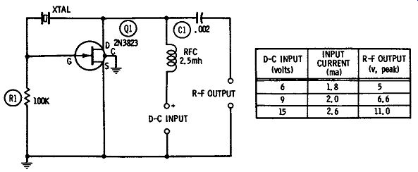
Fig. 9. Pierce crystal oscillator.
The operator must be familiar with the type of crystal he uses in this circuit, as the Pierce oscillator favors the fundamental frequency. Harmonic-type crystals operate here at their fundamental frequency only.
All wiring must be kept short and rigid. The case of the 2N3823 is connected to a fourth pigtail which should be grounded, as shown. Resistor R1 is 1/2 watt, and capacitor C1 should be a mica unit.
100-kHz CRYSTAL OSCILLATOR
A 100-kHz crystal oscillator is invaluable for use as a frequency standard and crystal calibrator. Fig. 10 shows the circuit of a simple oscillator of this type, employing a 2N3823 FET, which requires no tuning.
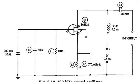
Fig. 10. 100-kHz crystal oscillator.
The circuit is a fast starter and vigorous oscillator. At 6 volts, 0.8 ma d-c input, the no-load r-f output is 5.4 volts rms, and this output is sufficiently nonsinusoidal that the 100-kHz harmonics may be detected far into the radio-frequency spectrum. If the oscillator frequency is to be set against standard-frequency signals from WWV or some other standard, the optional air trimmer capacitor C1 may be added. A 50-pf unit should allow the crystal frequency to be shifted sufficiently for the zero beating of a suitable harmonic with the high-frequency standard signal.
All wiring must be kept short, direct, and rigid. The metal case of the 2N3823 is connected to a fourth pigtail which should be grounded, as shown. Resistors R1 and R2 are 1/2 watt, and C2 and C3 are mica capacitors. ( The capacitance of C3 may need to be reduced in some applications to minimize loading of the oscillator.
In all instances, coupling should be as loose as possible. )
COLPITTS A-F OSCILLATOR
The Colpitts oscillator has the advantage that its inductor needs no tap, and no transformer is required for feedback. In spite of this simplicity, the oscillator is capable of a good output waveform and will operate at radio and audio frequencies.
Fig. 11 shows the circuit of a Colpitts a-f oscillator. While this is essentially a single-frequency unit ( 900 Hz), the frequency may be varied over a narrow range ( 650-900 Hz) if a slug-tuned, 5-henry inductor (United Transformer VIC-15, or equivalent) is used as shown in Fig. 11.
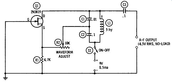
Fig. 11, Colpitts a-f oscillator.
This oscillator is built around a single plastic-encapsulated 2N3819 FET ( Q1). Direct-current drain is 0.5 ma at 9 volts, and the corresponding no-load output signal is 4.5 volts rms. With the aid of an oscilloscope or distortion meter connected to the A-F OUTPUT terminals, rheostat R2 may be set for best sine waveform.
The frequency may be changed by substituting other values for the C1 and C2 capacitances shown here; however, the 10:1 ratio must be preserved between C1 and C2. A small shift of frequency may be obtained, when a fixed inductor is used for L1, by varying only one capacitance. If, for example, L1 = 5 hy and C2 is changed to .07 mfd, the frequency becomes 1 kHz. However, rheostat R2 must then be readjusted for the best output waveform.
Source resistor R1 is 1/2 watt. Frequency-determining capacitors C1 and C2 must be high-grade units, for stability and good wave form. ( While mica is desirable, such capacitors are expensive in the large capacitances shown here; good plastic units are almost as satisfactory.) Output coupling capacitor C3 is a 100-volt plastic unit.
CODE-PRACTICE OSCILLATOR
An interesting application of the Colpitts circuit of the previous section is the code-practice oscillator shown in Fig. 12. In this unit, the magnetic headphones themselves supply the inductance of the frequency-determining circuit, and no other coil or transformer is needed.
This oscillator, which employs a single plastic-encapsulated 2N3819 FET (Q1), gives a hefty signal (a maximum output of 4.2 volts rms is developed across a pair of Trimm 2000-ohm magnetic headphones). Current drain is 0.8 ma at 9 vdc.
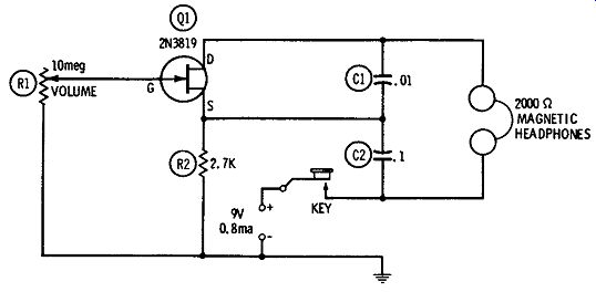
Fig. 12. Code-practice oscillator.
With the Trimm phones and with C1 = .01 mfd and C2 = 0.1 mfd, the signal frequency is approximately 1000 Hz. This can be changed by altering the C1 and C2 values while preserving their 10:1 capacitance ratio; however, limited frequency variation may also be obtained, without killing oscillation, by varying only C2.
The lower the capacitances, the higher the frequency is and vice versa.
The oscillator keys cleanly and has a good smooth tone. The headphone volume may be varied, with only slight effect on the frequency and waveform, by means of 10-megohm rheostat R1.
Since there is no current unless the key is depressed, there is no need for an ON-OFF switch.
Resistor R2 is 1/2 watt. The quality of capacitors C1 and C2 is not critical in this application, so both capacitors may be of any type that is convenient to the user. However, if frequency stability and excellent waveform are demanded, C1 and C2 should be good grade 100-volt plastic units.
[Note: This guide is based on Sams "FET Circuits", pub'd in 1961]