ENERGY sources for printed circuits and subminiature equipment have only recently begun to match the equipment itself in size and power requirements. Recent advances are refinements of long-known electrochemical systems. Few battery systems, however, even approach the transformer or electric motor in overall efficiency. The original Leclanche "carbon-mix" cell has progressed from a service life of 3 to 4 hours in 1912 to 12 and 15 hours today in flashlight applications. Industrial types of the D-cell have been made which yield 15 to 20 hours' use on low-resistance long-duration loads. Following the A-battery improvements have come the flat-cell techniques which make possible very compact B-batteries. Early hearing-aid B-batteries which yielded a useful life of only 10 to 20 hours now have lives measured in hundreds of hours on a comparable load basis. From hearing-aid battery design to printed-circuit and subminiature use has been a very short step.
Classification of batteries
Tradition classifies batteries into two main types-dry or wet, primary or secondary. Primary units are not made to be reusable; however, they can be recharged experimentally. The most common example is the ordinary carbon-mix flashlight cell in which the central electrode is a carbon rod, the outside zinc case is the remaining electrode, and the electrolyte is ammonium chloride.
Manganese dioxide is added to the central mix as a depolarizer.
This depolarizing action removes hydrogen which harms the cell.
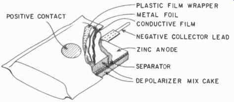
Fig. 401. A reversed-construction dry cell. (Courtesy National Carbon Co.)
A few improvements have been made recently, one of the most noteworthy being the "reversed" type of construction in which a carbon-coated jacket is put outside the cell and zinc sheets or vanes are distributed inside. The carbon jacket, inert to chemical attack, keeps the unit from leaking electrolyte even after the zinc is used up and the battery is dead.
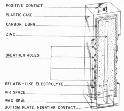
Fig. 402. An air-depolarized cell. (Courtesy National Carbon Co.)
The cell depolarizes somewhat better than the older type. A typical commercial unit is shown in Fig. 401.
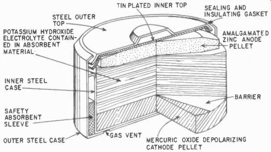
Fig. 403. Typical mercury cell. (Courtesy P. R. Mallory & Co.)
The drawbacks of poor shelf life, a drooping voltage-vs-time discharge curve, and sensitivity to temperature have kept this type of electrochemical system from widespread use in printed circuit and subminiature devices. This type of battery, however, is still low in first cost, and many users find it suitable for low-quantity applications.
Air cell
Shown in Fig. 402 is an air-depolarized cell which has a zinc center electrode and a porous carbon outside electrode. The mix is a jellylike composition, and the air diffuses through the porous carbon to depolarize the unit. It is activated by removing a tape seal which the manufacturer puts over the outside case of the battery. It has a flatter discharge curve than the Leclanche cell, but still possesses the inherent disadvantage of poor shelf life, even before the activating seal is removed.
Mercury cells
Developed out of wartime research, the mercury cell is pictured in Fig. 403. The main construction features of such cells are: 1) Cell cases and outer tops made of nickel-plated steel to resist external and internal corrosion; 2) Inner tops plated to provide internal surface for a zinc-amalgam bond; 3) Molded sealing gaskets of neoprene or polyethylene plastic; 4) Pressed-powder anodes made of high-purity pelleted zinc powder; 5) Pelleted mercuric-oxide-graphite depolarizing cathodes; 6) Permeable barrier between electrolyte and depolarizer; 7) Nickel-plated outer steel jacket and inner steel case, with an absorbent sleeve that vents gas built up in the cell and 8) Potassium hydroxide ( alkali) electrolyte held in absorbing material.
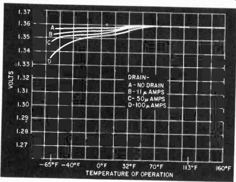
Fig. 404. Typical voltage-vs-temperature curve for a mercury cell.
Using the mercury cell
Fig. 404 shows a typical mercury cell voltage-vs-temperature curve under light current loads. Heavier loads tend to drag the voltage down more at the lower end of the temperature scale.
Most amateur and experimental uses are near room temperature so that drains of 10 to 500 ma can be obtained without severe low-temperature voltage losses.
Another interesting curve is shown in Fig. 405. At low drain Fig. 405. Typical voltage-vs-time curve of a mercury cell, and a 1-milliampere load, the voltage-time curve at room temperatures is extremely flat, suggesting the use of the cell as a voltage standard. Some commercial use has been recently made of this characteristic in potentiometer and measuring circuits.
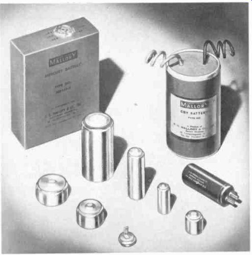
Fig. 406. Several typical mercury cells and batteries. (Courtesy P. R. Mallory & Co.)
Several typical cells and batteries are shown in Fig. 406. Button and tab connections are standard, but pigtail and plug-in units are available on order. Cells can be stacked in various series and parallel combinations to give higher voltage or current combinations.
One note of caution when using mercury cells: They should never be exposed to open flames or thrown into garbage dumps where there is a possibility of incineration. Like any other type of cell, extreme heat causes them to "pop," as would a closed can of beans under the same circumstances.
Primary-cell sizes and terminations
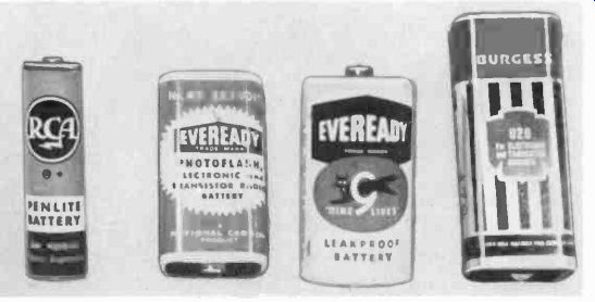
Fig. 407. Batteries for radios are available in a large number of sizes and
shapes.
Common sizes of cylindrical and flat primary units are given in Table 4-1.
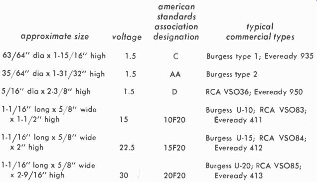
Table 4-1. Size and Voltages of Dry Batteries
D-, C-, and A-cells are more familiar as flashlight cells. The so-called penlite cells vary in size, some manufacturers referring to them as AA- and others calling them Z-size. Mercury units have been partially standardized around nominal diameters of 5/8 and 1 1/4 inches. The normal mercury cell voltage is 1.34. Common voltages for the carbon Leclanche types are also shown in Table 4-1. Terminations in wide use are plug-in socket type, snap fastener and flat contacts. The B-subminiatures also have a dimpled end construction. Representative A- and B-units are shown in Fig. 407.
Secondary cells
Silver-zinc cells are one of the most promising developments in the field of secondary-cell power sources, and several commercial models have found application in subminiature devices.
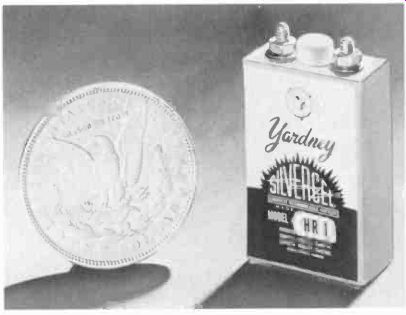
Fig. 408. A typical rechargeable silver-zinc battery. (Courtesy Yardney Laboratories.)
In contrast to lead-acid secondary systems, the silver-zinc cell ( Fig. 408) is capable of about four times the amp- and watt-hour ratings per pound of battery. A vital consideration in the design of silver-zinc cells is the method used to keep the zinc electrode in one piece and still maintain a barrier between silver and zinc ions. The original design did this by using a semipermeable membrane in a "jelly-roll" construction. Present techniques permit the zinc to be held at the surface of the zinc electrode and extend the total number of cycles of useful life. The separator also pre vents zinc from going over to the silver anode and silver from going back to the zinc cathode.
Water is consumed during the charging process, as shown by a decreased liquid level in the cell. In the dry-charged condition, the cell has a storage period which depends on temperature, humidity and atmospheric contaminants. Silver-zinc cells are noted for their high current rates on short-time discharges, but the cells can be modified to give low-current, longer-time characteristics. The cell evolves heat on high rate discharges. The temperature must be limited to values recommended by the manufacturer.
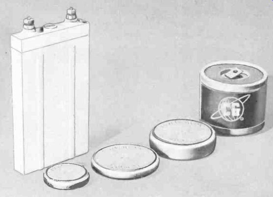
Fig. 409. An assortment of nickel-cadmium cells. (Courtesy CG Electronics & Gulton
Industries.)
Among the commercial types made is a low-rate cell capable of 100 to 150 charging cycles, and rated in the order of 1 amp-hour with a drain of 10 ma and a nominal cell voltage of 1.2. Other cells are capable of discharges in the order of tens of amperes for short periods of 1/2 to 4 or 5 hours.
In maintaining this cell, the liquid level above the plates should not be kept constant and, unlike lead-acid cells, there is no need for specific-gravity readings of the electrolyte.
Nickel-cadmium cells
The nickel-cadmium secondary cell is an outgrowth of German developments in the early 1900's. Recent versions have sintered nickel-nickel-hydroxide anodes, sintered nickel-cadmium-hydroxide cathodes, and utilize a potassium hydroxide electrolyte. Cells are usually cased in polystyrene, nylon or steel containers. The nominal cell voltage is 1.2.
The sintered-nickel electrodes are made by running carbonyl nickel, a compound of nickel and carbon, through a hydrogen atmosphere after pressing the powder into grids. The sintering process produces a highly porous plate with about 80% void volume. The electrode chemicals are then introduced into the pores by impregnation. Differences in commercial versions of the cells come from various techniques in the impregnation process.
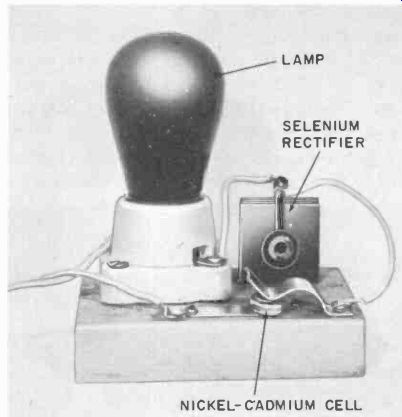
Fig. 410. Simple charger for nickel-cadmium cells. The lamp takes the place
of a dropping resistor.
An important feature of the nickel-cadmium reaction is that the specific gravity of the potassium-hydroxide electrolyte does not change appreciably during charge and discharge cycles.
Nickel-cadmium units appear to have the longest lives of all commercially available secondary cells, and are not as adversely affected by low temperatures as other types.
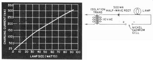
Fig. 411. Lamp-load come for the changer shown in Fig. 410.
Terminations of this type cell are either nut and screw or button. Smaller sizes (Fig 409) are finding large-scale application in subminiature electronic devices, and they can be recharged very easily with simple equipment.
Recharging nickel-cadmium cells
Fig. 410 shows a home-made charger for use with button type nickel-cadmium cells. These are available in three popular sizes ranging from 80 to 1,750 milliampere-hours (mah). ( Chargers of the type shown in Fig. 410 present a very real shock hazard.
Always use an isolation transformer between the charger and the power line.) These cells can also be charged from conventional car batteries by putting a 100-ohm 10-watt rheostat in series with the nickel-cadmium cell and one 2-volt section of the car battery.
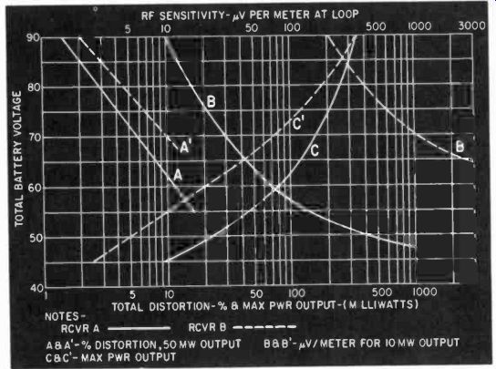
Fig. 412. Curves for B-battery rf performance. (Courtesy National Car bon
Co.)
A series milliammeter is a great help in adjusting the rheostat for a charging current of the desired value.
The curve in Fig. 411 shows the size lamp to be used to give the proper charging rate. In the case of the 250-mah cell, the cell can be fully recharged at a rate of 5 to 25 ma, which would call for a 10-watt lamp used to charge two cells in parallel, each cell taking about 25 of the 50 ma that the lamp passes. Charging current of the 500-mah unit is about 50 ma so that a single cell in series with the 10-watt lamp would be suitable.
Silver-cadmium cells
This cell is composed of a cadmium cathode in combination with a silver-oxide anode. Discharge voltages are in the range of 1.4 to 1.2. Two types of cadmium electrode are commercially produced. In the first, the active cadmium is put in a spongy material; in the second, the cadmium is impregnated. Silver-cadmium cells are generally slightly heavier than silver-zinc cells having the same volume of materials. Early research and experiments to date seem to indicate that the silver-cadmium cell is better adapted to shallow cycles and low discharge rates than the silver-zinc.
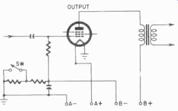
Fig. 413. Economizer circuit used to prolong B-battery life.
Using B–batteries
Unlike A-batteries in which current drain can be compared to discharge curves and life expectancies predicted, the life of the B-battery can be affected by several other factors. To say that a 22.5-volt B-battery is no good when its voltage under load drops to 18 is not sufficient. The B-battery end-point voltage is deter mined by rf considerations, output distortion in the circuit, maximum power requirements of the circuit, and oscillator stability in the case of oscillatory circuits.
Rf sensitivity is arbitrarily determined by choosing a transmitter, setting up a radiation pattern with known field strength and modulation, and making tests on the output of the receiving device. In the case of broadcast receivers, a typical set of conditions might be a field strength of 1,250 microvolts per meter at 1,000 khz, modulated 30% at 400 cycles to give an audio output at the receiver of 10 milliwatts. Fig. 412 compares two receivers.
Note that receiver A is a better design since, for a given B-battery end-point voltage, the maximum power output is greater and the required input signal for a given output is less. Receiver A can be used down to a 45-volt end point ( from a 90-volt original emf ) before the 10-mw output point is reached, but receiver B falls short at about a 68-volt end point due to the sensitivity figure going up above 1,250 microvolts per meter for the 10 mw output.
Battery performance

Table 4-2 .Charging Rates and Times for Dry Cells: type of cell , charge rote charge time end voltage
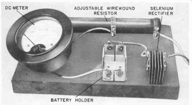
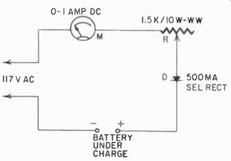
Fig. 414. Setup for rejuvenating dry cells. The table supplies the charging
rate and time for various types of cells.
Antenna design affects B-battery performance, since it is tied up with rf sensitivity through the Q of the antenna circuit. A high Q antenna, such as a ferrite or ceramic-ferrite-core loop, can improve B-battery life expectancy considerably.
Many circuit combinations are possible in which A- and B-battery characteristics are not matched for best life. The answer to such a problem is to ask for the battery manufacturer's recommendations.
A circuit for B-battery conservation is shown in Fig. 413. It consists of a self-bias resistor which has two sections. There is a shorting switch across one of these sections and, when the B-battery is new, the switch is left open. This over biases the output tube and also reduces plate and screen currents of the other tubes in the receiver. When the B-voltage falls off in use, the switch is closed.
This shorts the bias resistor and gives more power output. The disadvantages of such a circuit are that initial power is reduced a little and distortion is increased. However, the amount of power reduction and distortion is not enough to bother the average listener.
Testing batteries
No single standard exists today for battery testing. Each manufacturer makes special tests on his own batteries and those of his competitors. However, the American Standards Association has compiled a specification for dry cells and batteries under the sponsorship of the National Bureau of Standards. The specification ( ASA C18.1-1959) has been issued by the National Bureau of Standards as their circular No. 559. Tests are usually based on a load condition that. varies with severity of service and time. The purpose of each test is to simulate as closely as possible the actual conditions under which the battery will be used. Tests are normally made at 70°F.
Recharging dry cells
Although not recharging in the sense that reversal of chemical reaction occurs, a technique can be used to rejuvenate the Leclanche type of A- and B-battery. The process is really a depolarization effect in which the oxygen that collects on the carbon anode in discharge is driven off in recharging.
Fig. 414 shows a setup for rejuvenation experiments. A half-wave rectifier and resistor are used with a series ammeter (0-1,000 ma) and parallel voltmeter to furnish a dc supply adjustable for 1.5- to 30-volt batteries. Fig. 414 also shows the schematic and gives an approximate guide to what you can expect in the way of charging rates and times.
Several factors influence the success of recharging dry batteries. These include the formula of the battery mix, the age of the battery, the amount of moisture left in the battery and, probably the most important, the duty to which the battery was subjected prior to recharging. A battery that was used on short, light loads would be more likely to recharge successfully for more cycles than a heavily loaded one. After recharging, the battery should be left sitting for a few hours to allow the voltage to stabilize.
Otherwise, it will be somewhat erratic when it is first used after being recharged.