AMAZON multi-meters discounts
AMAZON oscilloscope discounts
Transistorized oscillators are unique in their ability to operate with good efficiency at dc power inputs of extremely low level.
Oscillation has been obtained when the transistor bias consisted of a few microwatts of dc supplied by such an unconventional source as a thermocouple, photocell, charged capacitor or saliva-and-coin makeshift wet cell.
Practical af and rf transistor oscillators are feasible in a wide variety of output power ratings. Like transistorized amplifiers, transistor oscillators make efficient use of their dc supplies. Because of the low power drain when using conventional small transistors, these oscillators are free from the high heating effects which cause severe frequency drift in vacuum-tube oscillators.
Single-frequency audio oscillator
Fig. 401 shows the circuit of a single-frequency audio oscillator of the tickler-feedback type.
Employing a Raytheon CK722 transistor, this circuit delivers a maximum output of 0.65 volt rms into a high-impedance load. Direct-current drain is 8 to 10 u-a at L5 volts. Higher-voltage batteries (up to 6 volts) will give larger audio output with increased dc drain.
The operating frequency is determined by the inductance of the low-impedance winding of transformer T and the capacitance C1.
A 0.05-uF capacitor with the transformer specified in Fig. 401 gives a frequency of approximately 1,000 cycles. The frequency may be raised by decreasing C1 and lowered by increasing this capacitance.
Transformer T must be connected as shown, according to the manufacturer's color coding to obtain feedback of the proper polarity for oscillation.
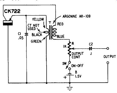
Fig. 401. Single-frequency audio oscillator.
The output waveform may be improved (distortion reduced) , as required by individual demands, by a resistance connected in the external base lead of the transistor. The amount of resistance, 200 ohms or higher, must be determined experimentally for an individual transistor and transformer.
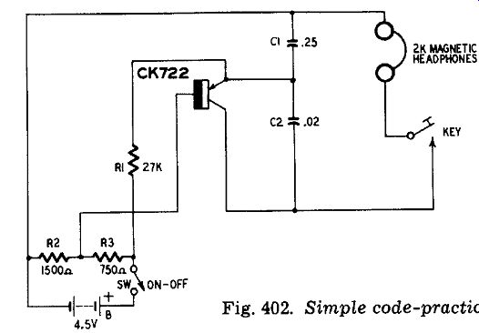
Fig. 402. Simple code-practice oscillator.
Simple code-practice oscillator The magnet coils of a pair of headphones supply the required inductance in the audio oscillator circuit shown in Fig. 402. This' arrangement makes a convenient code-practice oscillator of the Colpitts type, in which the operating frequency is determined by the capacitance combination C1-C2 and the headphone inductance. A Raytheon CK722 transistor is employed.
The headphones must be of the magnetic type. Crystal units are inoperative in this circuit. With a pair of Trimm 2,000-ohm headphones and with C1 = .25 µf and C2 = .02 uf, the operating frequency was measured as 750 cycles. The frequency may be raised by decreasing both C1 and C2 and lowered by increasing their values. At any chosen frequency, the ratio between the two capacitances must be approximately 10 to 1, as shown in Fig. 402.
Total direct-current drain is approximately 3 ma. A 50,000-ohm potentiometer may be connected as a volume control, if desired, in series with the collector lead of the transistor.
Loudspeaker-operating code-practice oscillator
Classroom code instruction often requires the use of a loudspeaker. This enables the instructor to give verbal directions while demonstrating sound signals-a task not easily performed when students are wearing headphones.
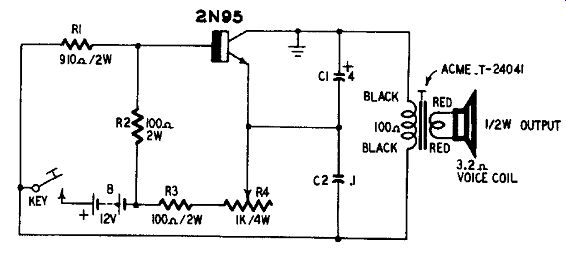
Fig. 403. Loudspeaker-operating code-practice oscillator.
Fig. 403 shows the circuit of a code-practice oscillator which will deliver 0.5 watt of audio power to a loudspeaker. This output is adequate for small- and medium-sized classrooms. A Sylvania 2N95 power transistor is operated from a 12-volt battery.
This oscillator employs a Colpitts-type circuit, similar to the low-powered oscillator described earlier. The frequency is deter mined by the inductance of the primary winding of transformer T and the capacitance of the C1-C2 combination. Using the trans former and the capacitances specified in Fig. 403, the frequency is approximately 360 cycles at the lowest-resistance setting of potentiometer R4. The frequency increases to approximately 3,500 cycles when R4 is set to its full resistance of 1,000 ohms. This gives a frequency range of nearly 10 to 1.
The dc drain when the key is closed is 170 ma. Because of the intermittent nature of code-practice oscillator service, the operating current may be supplied by a battery of size-D flashlight cells if compactness is a requirement.
Phase-shift audio oscillator
The vacuum-tube phase-shift oscillator is noted for its simplicity and low distortion. In this circuit, the operating frequency is determined by the resistance and capacitance values in a three-leg R-C network which transmits feedback voltage in the proper phase for oscillation. This phase-shift network is connected between plate output and grid input of a single-tube stage.
Many experimenters have failed to apply the phase-shift principle successfully to transistorized oscillators. The main reasons for poor results have been (1) failure to take into consideration the influences of the transistor input impedance on the phase-shift network parameters and (2) insufficient amplification in the transistor stage.
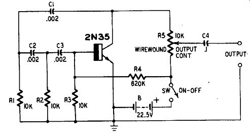
Fig. 404. Phase-shift audio oscillator.
In the oscillator circuit shown in Fig. 404, the required 180 degrees of phase shift are provided by the R-C network C1-C2-C3--R1-R2-R3. The resistance values in this network have been chosen with respect to the transistor input resistance shunting resistor R3.
The R and C values have been selected for 2,000-cycle oscillation, Adequate gain is provided by the Sylvania 2N35 transistor in the common-emitter circuit.
The maximum signal-output voltage across a high-impedance load is 3.5 volts rms when OUTPUT CONTROL. R5 is set to maximum.
Total harmonic distortion is 0.26%. Total dc drain is 1.1 ma from the 22.5-volt battery. Resistor R4 acts with the frequency-network resistor R3 to form a voltage divider for base-bias stabilization.
The oscillator frequency may be altered by changing the value of each network capacitor (C1, C2, C3) by the same amount.
Increasing the capacitance lowers the frequency and vice versa.
For low-impedance output with approximately 12-db power gain, a common-collector amplifier stage may be added to the phase-shift oscillator.
Step-type variable-frequency audio oscillator
The basic tickler-feedback circuit given in Fig. 401 may be modified to deliver several selected frequencies by providing switched capacitors to tune the transformer winding. Fig. 405 shows such a simple, step-type, variable-frequency oscillator circuit.
Capacitors C1, C2, C3 and C4 are selected experimentally for the desired frequencies. The capacitances will vary somewhat for individual transformers, depending upon the primary inductance of T, hence are not specified here. The capacitors are switched successively into the circuit in parallel with the transformer primary by switch S1. All other circuit constants are the same as those given in Fig. 401.
Tuned variable-frequency audio oscillator Step-type frequency control is limited to those applications calling for discrete test frequencies only. Most applications require, not spot frequencies, but a continuous smooth variation of oscillator frequency. Simple step-type oscillators such as the circuit shown in Fig. 405 or a smaller switched-capacitor version of Fig. 404, accordingly are special-purpose devices.
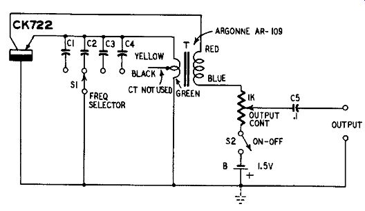
Fig. 405. Step-type variable-frequency audio oscillator.
Fig. 406 shows the circuit of a smoothly tuned variable-frequency audio oscillator covering the range 200 to 10,000 cycles in one complete turn of the tuning dial. This is a resistance-tuned oscillator based upon the Villard selective amplifier. Employing four General Electric 2N107 transistors, this oscillator delivers 0.75 volt rms open circuit. Its output is low-impedance. Higher output may be obtained with an output booster amplifier stage.
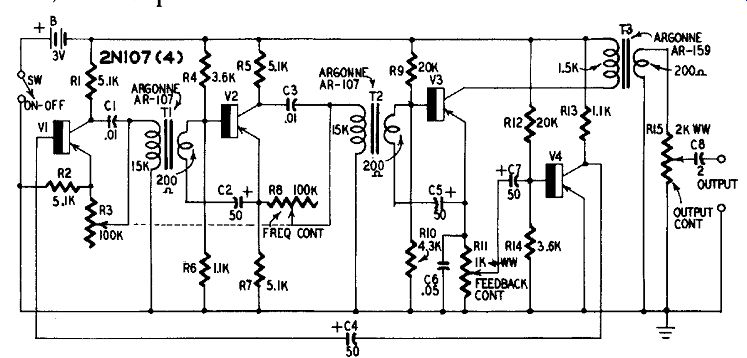
Fig. 406. Tuned variable-frequency audio oscillator.
Tuned phase-shift networks (C1-R3 and C3-R8) are included in the first two transistor amplifier stages ( V1 and V2) The adjustable arms of these networks are supplied by the dual, ganged 100,000-ohm potentiometer R3-R8. The two sections of this control must track closely and each must have an audio taper. This potentiometer is the frequency control and its dial may be calibrated to read directly in cycles per second.
The final transistor stage (V4) provides the regenerative feed back, through capacitor C4, required for oscillation. Oscillation occurs at the single frequency at which zero phase shift is provided by the C1 R3-C3 R8 network. The degree of oscillation is governed by the setting of the feedback-control potentiometer R11. By set ting this control to the point at which the circuit just begins to oscillate stably, output-signal distortion may be held to 1% or less.
Under these conditions it may be necessary to readjust R11 for oscillation as the frequency is shifted throughout the tuning range.
The polarity of connections to the transformers T1 and T2 is very important. If the circuit fails to oscillate or does not cover the 200-10,000-cycle range, the primary connections of T1 or T2 (but not both) should be reversed. All three transformers in the circuit must be mounted far enough apart and oriented so that no interaction occurs between their magnetic fields.
100- khz crystal oscillator
Fig. 407 shows the circuit of a 100- khz crystal oscillator suitable for use as a secondary frequency standard or general-purpose experimental signal source. This oscillator employs a Sylvania 2N94 transistor as a common-base oscillator and a Sylvania 2N34 as a common-collector output amplifier. Single-battery operation is made possible through this use of an n-p-n transistor in the common-base stage and a p-n-p in the common-collector stage.
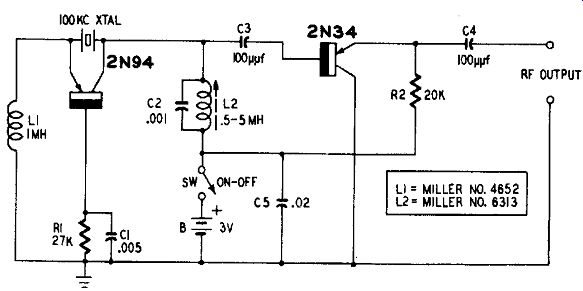
Fig. 407. 100-khz crystal oscillator.
The oscillator is tuned to the crystal frequency by adjusting the slug in inductor L2 for peak deflection of an rf vacuum-tube volt meter connected to the RF OUTPUT terminals. For maximum stability, capacitors C2 and C3 must be of the silvered mica type.
The open-circuit output-signal voltage is approximately-0.8 volt rms. The total, dc drain is less than 1 ma from the 3-volt battery B.
For long service at constant voltage, it is recommended that B consist of two mercury cells (Mallory RM1R) connected in series (total voltage _-_- 2.69 volts) .
Self-excited 100-khz oscillator
Fig. 408 shows the circuit of a simple, self-excited 100- khz oscillator employing a single Raytheon 2N112/CK760 rf transistor. Drawing a total direct current of 1.25 ma, this oscillator possesses good stability and is recommended for applications not demanding the high stability of a crystal oscillator.
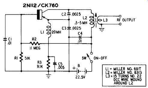
Fig. 408. Self-excited 100-khz oscillator.
A Colpitts-type oscillator circuit is employed. The operating frequency may be set exactly to 100 khz by the conventional zero-beat method using WWV transmissions, by adjustment of the tuning slug in inductor L2.
The signal-output coupling coil L3 consists of 15 turns of No. 22 dcc wire wound tightly around the outside of L2. This coupling coil delivers an open-circuit rf signal output voltage of approximately 1 volt rms.
Stabilizing dc base bias is provided by the voltage divider R1-R2.
The radio-frequency choke L1, prevents grounding the rf component of emitter current.
High-frequency crystal oscillator
The oscillator circuit shown in Fig. 409 may be used with crystals having fundamental frequencies up to 7.5 mhz. Employing a Sylvania 2N94A rf transistor, this is a conventional, collector-tuned, common-base circuit.
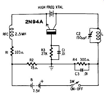
Fig. 409. High-frequency crystal oscillator.
A 7.5-volt battery (B) supplies the bias currents. A voltage divider is formed by resistors R2 and R4 in series. Emitter bias of 1.5 volts is developed by the voltage drop across resistor R2. Collector bias of 6 volts is developed by the voltage drop across R4. The bleeder (voltage-divider) direct current is 20 ma. This high value is required for stabilization of the 4-ma emitter and collector currents. Total dc drain is 28 to 30 ma.
The collector-tuned circuit L-C2 is resonated to the crystal frequency by means of variable capacitor C2. The coil may be wound for a particular crystal frequency according to tables and directions found in amateur radio handbooks. Tuning is indicated by peak deflection of an rf vacuum-tube voltmeter or crystal-diode meter inductively coupled to the tank coil L. The rf voltage developed across coil L at resonance is approximately 5 volts rms.
Energy may be coupled out of the collector tank by conventional capacitance coupling, inductive coupling or link coupling to coil L.
Self-excited rf oscillator
Fig. 410 shows the circuit of a self-excited Hartley-type oscillator having a continuous tuning range of 500 khz to 4.5 mhz. This stabilized circuit, employing a Sylvania 2N94 rf transistor, has a radio-frequency output of 0.65 volt rms (open circuit) and a total drain of 2 ma dc.
Tuning is accomplished with a single-section 350- or 365- Rif vari able capacitor C2. The tuning range may be set with the aid of the 1260411A padder capacitor C1 and the tuning slug of inductor L.
Inductor L is a miniature, commercial, transistor-type, high-Q oscillator coil assembly, consisting of a two-tap main coil and a secondary coupling coil. The figures shown on the coil terminals in Fig. 410 correspond to the manufacturer's labeling and must be followed to obtain oscillation.
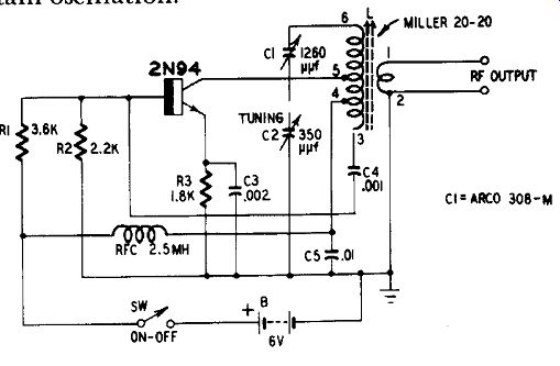
Fig. 410. Self-excited rf oscillator.
Base bias stabilization is provided by the voltage divider R1-R2.
The radio-frequency choke (RFC) prevents the grounding through the voltage divider of rf energy from the output tank circuit. Emitter current-limiting resistor R3 is bypassed by capacitor C3 to pre vent reduction of gain from degeneration.
Wide-range rf oscillator
Radio-frequency transistors have made possible the design of oscillators operating at higher frequencies than the standard broad cast band. The circuit shown in Fig. 411 employs a Philco SB100 surface-barrier transistor and oscillates as high as 44 mhz. Specially picked transistors possibly will oscillate at somewhat higher frequencies.
This tickler-feedback circuit employs either plug-in coils or coil switching. L2 is the tuned collector coil and L1 the low –impedance base tickler. For each frequency band, both coils are wound on the same form. The frequency coverage provided by the oscillator is
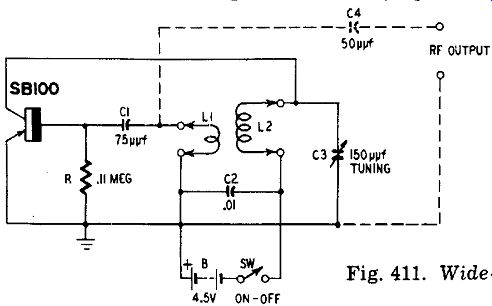
Fig. 411. Wide-range rf oscillator.
1 to 44 mhz in four bands: 1-2.7, 2.5-7, 6-17 and 15-44.
Table 4 gives winding instructions for the coils.
Rf output may be taken from the oscillator through capacitance coupling to the tickler coil, as shown by the dashed lines, or link coupling may be provided by two or three turns of the same size wire used in L2 and wound as close as possible to the ground end of L2.
Total dc drain of the oscillator is approximately 1.1 ma from the 4.5-volt battery B.

Table 4-Coil Table for Rf Oscillator
------------
Band A
L1: 25 turns No. 30 enameled wire closewound 1-2.7 mhz over ground end of L2.
L2: 100 turns No. 30 enameled wire close-wound on 1-inch-diameter form.
Band B L1: 9 turns No. 24 enameled wire closewound 2.5-7 mhz over ground end of L2.
L2: 35 turns No. 24 enameled wire closewound on 1-inch-diameter form. Space to winding length of 3/4 inch.
Band C L1: 7 turns No. 24 enameled wire closewound 6-17 mhz over ground end of L2.
L2: 23 turns No. 24 enameled wire closewound on 1/2-inch diameter form.
Band D L1: 7 turns No. 20 enameled wire closewound 15-44 mhz adjacent to ground end of L2 .
L2: 9 turns No. 20 enameled wire on 1/2-inch diameter form. Space to winding length of V, inch.
----------------------
Multivibrator
The multivibrator circuit shown in Fig. 412 is analogous to the symmetrical vacuum-tube multivibrator. Like the tube circuit, it consists of a two-stage R-C-coupled amplifier with positive feedback (through capacitor C4) from the second-stage output to the first-stage input. The n-p-n transistors are Sylvania 2N35.
With the circuit constants shown, the natural frequency of this multivibrator is approximately 2,000 cycles. For this symmetrical
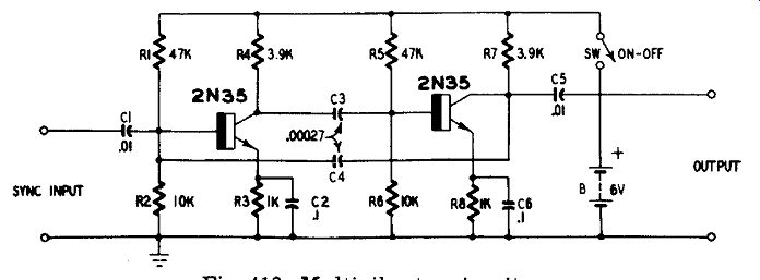
Fig. 412. Multivibrator circuit.
circuit the approximate operating frequency f = 1,000/ (2RC) , where f is the frequency in kilocycles, C the capacitance in micro farads of either C3 or C4 (both have the same capacitance value) and R the transistor input resistance. The latter will vary between 900 and 1,200 ohms with individual transistors. To change the frequency, both C3 and C4 must be changed by the same amount; increase the capacitance to decrease the frequency and vice versa.
The peak-to-peak output is approximately 2.5 volts. Total dc drain is 1.6 ma from the 6-volt battery B. The multivibrator may be synchronized readily by means of a 7-volt peak signal (sinusoidal or nonsinusoidal) applied to the SYNC INPUT terminals.
Blocking oscillator
Fig. 413 shows the circuit of a simple blocking oscillator designed for 1-Itsec output pulses at a repetition rate of 10 khz. For fast rise time, an n-p-n rf transistor ( Sylvania 2N94) is employed.
Operation of this circuit is somewhat similar to that of a vacuum-tube blocking oscillator. The transistor collector current normally is held at cutoff by the negative base bias due to the charge in capacitor C2. A positive pulse applied to the TRIGGER INPUT terminals momentarily discharges C2 through resistors R1 and R2 and causes collector current to flow. The circuit oscillates during this interval, which is determined by the C2-R1-R2 time constant because of positive feedback through the pulse transformer T. The peak amplitude of the positive input-trigger pulse must be better than 3 volts. The output-pulse duration is adjustable by means of rheostat R2.
Pulse-output voltage is delivered by the third winding of trans former T through capacitor C3.
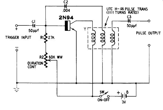
Fig. 413. Blocking oscillator circuit.
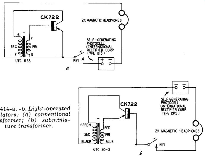
Fig. 414-a,-b. Light-operated oscillators: (a) conventional transformer; (b)
subminiature transformer.
Light-powered oscillators
The high efficiency of the junction transistor and its ability to operate at extremely low collector voltage make possible practical oscillators operated from microwatt dc supplies. A typical example is the light-powered oscillator in which the dc collector bias is sup plied by a self-generating photocell.
Two light-operated oscillator circuits are shown in Fig. 414.
While these are wired as code-practice oscillators, they may (by re placing the telegraph key with an on-off switch) be employed in any other application utilizing a tone signal generated by the action of light rays. The circuit becomes a telegraph when the headphones are removed to the distant end of a two-wire line running from the oscillator.
Self-generating selenium photocells are used in each circuit. Fig. 414-a uses a standard-size audio transformer for feedback while Fig. 414-b employs a subminiature unit. In Fig. 414-a, the tone frequency is approximately 2,000 cycles when the photocell is illuminated by moderate sunlight. The frequency decreases as the light intensity increases and vice versa. In Fig. 414-b, the frequency is ap proximately 900 cycles. In each circuit, the frequency may be lowered by connecting a capacitor in parallel with the secondary of the transformer.
Each circuit will operate with artificial illumination as well as with sunlight. In subdued room light, the arrangement shown in Fig. 414-b will develop a signal of 0.02 my rms across 2,000-ohm magnetic headphones. A 100-watt incandescent lamp 1 foot from the photocell produces a 0.5-mv rms signal. From 1 to 2 millivolts can be obtained when the photocell is in direct sunlight.
Oscillator operating notes
To obtain maximum performance from transistorized oscillators and to protect the transistors from accidental burnout, some pre cautions are necessary that often can be neglected in amplifier operation.
Keeping within maximum dissipation ratings is very important.
When no power is drawn from the oscillator, the transistor is called upon to dissipate the entire dc power input. The heating can destroy the transistor if it is excessive. When the oscillator must be unloaded, check the collector current and voltage values to be sure that the product V,. X I does not exceed the maximum allow able dissipation. At elevated ambient temperatures, the allowable dissipation falls. Follow the derating procedure recommended by the transistor manufacturer.
Heat sinks should be provided when power transistors are operated at their full ratings in oscillators. This will prevent heat destruction of the transistor. While bolting the power transistor to the metal chassis will suffice in most instances, a special large-area sink may be required for some types of operation where dissipation is high. Consult the transistor manufacturer's literature for definite requirements.
Use "stiff" dc bias networks to prevent collector current runaway.
Where required, such networks are shown in the circuits in this guide. An oscillator often is more inclined toward runaway than is an amplifier using the same transistor and dc voltages.
In audio oscillators, examine the waveform of the output signal, using an oscilloscope or harmonic distortion meter. The distortion percentage tends to run somewhat higher than in comparable tube oscillators because of semiconductor nonlinearity. Usually, one or more components in the circuit can be adjusted (with an individual transistor) to reduce distortion significantly.
Because the internal capacitances of audio transistors are high, tank loading can be severe in oscillator circuits. For this reason, it is a good idea to tap the transistor down the tuned circuit (when one is employed), whenever possible, instead of connecting it across the full tank.
REFERENCES
1 Rufus P. Turner, Novel Transistor Code Practice Oscillator, Popular Electronics, April, 1955; p. 88.
2 Rufus P. Turner, (Guy Dexter) , Transistorized Code-Practice Oscillator, Radio & Television News, April, 1956; p. 126.
3 Rufus P. Turner, Transistorized Phase-Shift Oscillator, Radio & Television News, April, 1956; p. 108.
4 Rufus P. Turner, Transistor Oscillator Is Powered by Light, RADIO- E LECTRON I CS Magazine, August, 1953; p. 66.
5. Rufus P. Turner, Experiments With Simple Solar Batteries, Popular Electronics, November, 1955; p. 66.