Simple touch-sensitive piano using ready-made keyboard -- part 1
by G. Cowie, B.Sc.
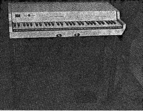
The instrument described is a simple touch-sensitive electronic piano which is small and portable.
The circuitry is designed on a modular basis using ICs extensively and is not difficult to construct.
It generates tones by an oscillator-divider system, the tones being keyed by individual touch-sensitive key circuits. Costing around (mult. by 1.25 for USD ) £70 to build, the design is believed to be the most cost-effective available, in terms of what it is intended to do, and a commercial instrument with this touch-sensitive feature would seem to cost at least (mult. by 1.25 for USD ) £300.
This design was built to fill a real need; if there had been an acceptable instrument on the market I would have bought it instead of spending three months and (mult. by 1.25 for USD ) £50 in making one. I was learning to play the piano and wanted an instrument of my own for practice. As 1 live in furnished flats, moving frequently, a full-sized upright just was not practicable. The alternatives were a "mini" piano or an electronic piano. I ruled out the first on finding that second-hand instruments were surprisingly expensive because of the demand; moreover they were not portable enough.
This left electronic pianos. I looked at several but they cost a lot of money and I did not like them. The trouble is that they all have the same artificial keying action in which pressing the key beyond a certain point suddenly generates a note of fixed loudness. On the cheaper instruments the note cannot be held after the key is released, I wanted an instrument which behaved just like a string piano, even if it did not sound much like one. The prototype is quite true to my original intentions: if you play loud the sound comes out loud, if you play very softly the. sound hardly comes out at all. In playing a chord, one can make some notes loud and others soft at the same time. There is a "loud" pedal which can be used to. sustain notes after the key is released, and the sound dies away just as in a real piano.
The low notes have long decay time constants, and the high notes have very short time constants. The tone is a bit like that of an electric piano, a harpsichord, and an electric guitar. Most listeners find the tone pleasant; it is much less harsh than that of a real piano. In any case to imitate a grand piano perfectly would be very difficult Most important of all, the instrument is about the size of a large suitcase and light enough to be carried by one person.
The essential feature of the design is that* the volume of sound generated depends on how fast the key is pushed down, a feature not then available to my knowledge on any other electronic piano.
This feature is what makes a pianoforte what it is, and its importance was impressed on me by a musician friend with whom I discussed the project. In simple terms, the effect is to add a new dimension, that of loudness, to the sound. Although 1 made no attempt to vary the tone along with the volume, the characteristics of the human ear and of the power amplifier cause such an effect with my instrument.
I find the instrument sufficiently interesting to play that I have not found it necessary to add tone-shaping circuits though this could be done quite easily. The only extra is a swell pedal which is useful for increasing the dynamic range. Functionally, the instrument is much the same as a string piano, except that there is no "soft" pedal.
Purists may argue that the key action is not the same as that of a real piano. Strictly speaking this is so, but the art of playing the electronic piano is so similar to the art of playing a real one that there is no difficulty in changing from one to the other.
To produce an electronic imitation of a real piano would be an ambitious undertaking, and potentially an uneconomic one.
If the imitation is to be useful by reason of its small bulk and competitive cost then compromises are necessary. The sound that a piano makes has a complex harmonic content. This is not an insuperable difficulty in itself, but the harmonic content varies according to the loudness with which the note is struck, and with time; it is also different for notes of different pitches, Loudness of course varies with time, with a fast attack and slow decay. As if this weren't enough to contend with, most of the notes employ two or three strings which do not vibrate in perfect unison.
The keys of a piano have a characteristic feel when pressed down by the finger; there is a constant resisting force caused by the weight of parts on the inner end of the key, a reactive component caused by the inertia of the fast-moving hammer, and a small amount of friction. The harder one tries to play, the greater the reactive part of the opposing force becomes. From the musician's point of view this characteristic of the piano is most desirable, as it makes it easier to exploit the touch-sensitive loudness which is inherent in the piano.
The faster the key goes down, the faster the hammer moves, the harder the hammer hits the strings, the louder the sound. Music tutors exhort one to think of the key speed rather than the pressure. Technically this makes sense as only the final speed of the hammer matters and it is easier to accelerate it by a smooth pressure than by jabbing the key (and the music sounds better). In this piano design, each key is linked to its own timing circuit so that sound output depends on the average velocity with which a key is pushed down.
Various electronic pianos are on the market. Those priced competitively with respect to conventional uprights seem to adopt similar solutions to the problems outlined above. Keyboards are similar to those used in electronic organs, with the same touch, and most of the instruments are not touch-sensitive at all. One infers that the acoustic waveforms are square waves treated by low-pass filters, and by highpass filters for special effects. All have the right sort of fast attack, slow decay as this is very easy to effect for square waves.
Again by inference the frequency generation is done by oscillators and dividers as in electronic organs.
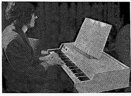
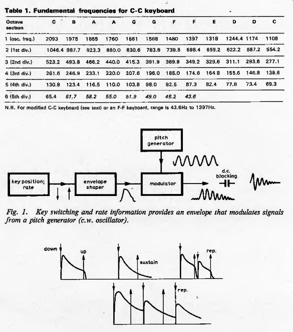
Table 1. Fundamental frequencies for C-C keyboard
Fig. 1. Key switching and rate information provides an envelope that modulates
signals from a pitch generator (c.w. oscillator).
Fig. 2. These envelope waveforms are determined by switches actuated by keys and the sustain pedal. Diagrams show single and repeated notes with and without sustain action.
Design considerations
After preliminary thought and discussion, I decided that my electronic piano would be touch-sensitive, have a sustain pedal, use square-waves as the working waveform, and have twelve master oscillators, using TTL. 7493 integrated-circuit frequency dividers to generate the lower pitches. On seeing ready-made organ keyboards and key-switches I decided to use these and, as five octaves is a standard size, that the little-used top and bottom octaves of the conventional 88-note piano keyboard could be dispensed with. This simplifies the work considerably and makes the finished instrument significantly smaller and lighter.
The essential features of electronic key circuit are shown in Fig. 1. The key position must be determined electrically, to control an envelope shaper whose output is used to modulate the amplitude of a continuous-pitch waveform. Tone is determined by the pitch waveform, and attack and decay are determined by the envelope. As the piano is to be touch sensitive then the initial height of the envelope must be variable.
A number of envelope waveforms are shown in the Fig. 2. These show a note played and released, a note played and sustained, and notes repeated without and with sustain. Generally, electrical key contacts are used to signal the states "up", "down" and "moving" and this can be done by a single contact moving between two busbars. But I found that the simplest and cheapest system must use more contacts to simplify the electronics. An electronic piano must have an electronic switch to block the pitch signal when it is not required; in my circuit a diode is used.
Twelve oscillators generate the twelve pitches for an octave, and the pitches for lower octaves are obtained by dividing by 2,4, 8, 16 (Table 1).
The oscillators use operational amplifiers instead of LC circuits --it is cheaper to buy opamps than to buy special coils.
Also, the op-amp circuit is easier to design and can be tuned by a cheap pre set potentiometer, A detailed discussion of this type of oscillator is given in Electronic Engineering, Nov. 1971, page 54. Complex MOS microcircuits are now available which wilt produce the twelve top-octave frequencies when driven by a radiofrequency master oscillator. Thus all the key pitches are synchronized with the master oscillator and the organ or piano never needs retuning. Such a device would add about (mult. by 1.25 for USD ) £3 to the cost of the project and a suitable (optional) module will be described in part 3 of this article.
Regulated supplies of +5 and -5 volts are provided as a regulated 5-volt supply was needed in any case for the t.t.1. divider circuits. The advantages of integrated-circuit frequency dividers over discrete dividers in cost, time, space etc are such as to make them the only choice. About half of the piano circuitry is inside the divider i.e. packages.
I devoted much thought to making the key circuits as simple as possible. As there are sixty-one key circuits, elimination of even one component could save hours of work and pounds of hard cash. Wood was the obvious choice of material for the case.. The case is styled after my own conception of how an electronic piano should look, and has no lid as this wasn't essential and would not fit into the design. There is more room at the rear of the case than is strictly necessary; this was deliberate in that making the case too big would cause nothing like as much trouble as making it too small.
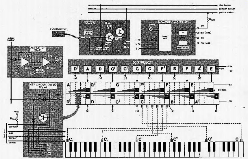
Fig. 3. Time between 82 and S ^ S, opening as the key is pressed determines
loudness of sound, achieved with the key circuit. Twelve RC oscillators feed
12 dividers (shown above keyboard in diagram), giving 60 of the 61 tones
for modulation by the key circuits. For a five-octave keyboard 61 tones are
actually required, the additional tone (C1 ) being provided by a 13th divider,
as the ICs will only divide by a maximum of 16. Outputs from the key circuits
are mixed in the amplifier via the output busbar. Three of the busbars run
alongside the keyboard so that three key switch leads can be directly soldered
to them /C-m is 1 k-O.
Circuit Description
Fig. 3 is a schematic diagram of the complete circuitry which is too complex to be drawn in full. Under the keyboard are 61 sets of three normally-closed gold-plated wire switches, one set being shown.
One pole of each switch is connected to one of three busbars which run under the keyboard. The other poles are wired to a key circuit, which is one of a letter-group of five as there are five octaves; and there are twelve letter-groups. There is a sixth note C for which an extra key circuit and an extra divider to give 32 provided.
Each letter-group of key circuits is fed with signals from an oscillator and frequency divider. The key circuit for one note is drawn in full to show the interconnections.
To each of the 61 key switches six connections are made. Three of these are common busbars (bias, damper, switch), and the other three are bias, damper, and switch signal lines and all go to One key circuit, linking the key to the electronics.
The power supply feeds +5 volts to the oscillators, frequency dividers, summing preamplifier and output amplifier and, via a resistor, to the collector bus which feeds all 61 key circuits. It also feeds an unregulated +8-volt supply to the switch bus, and -5 volts to the oscillators and amplifiers.
The output bus is a virtual earth line fed from all 61 key circuits. The bias and damper buses are controlled by the sustain pedal.
Key circuits
Though the key circuits appear simple (Fig. 4), each has three sections which are more or less analogous to parts of a string piano. Components C1, R1, R2, S1, S2, form a velocity-measuring circuit which gives the piano its touch-sensitive property. The charge in C,, when the key is depressed, represents hammer velocity. Transistor Tr1 provides isolation between the input and output sections of the circuit --the equivalent in a real piano is a device allowing the hammer to fall back. Capacitor C2 has a charge representing the vibrational energy of a string. Components D2, S3, R3 form the damper circuit, which may be disabled to give a sustain action.
Diode D1 blocks the pitch signal when the circuit is on standby and, when the circuit is active, forms a chopper and output circuit with R4 and R5s.
The discharge times of capacitors C2 vary to imitate the peculiarity of the string piano whereby bass notes die away more slowly than the treble.
Velocity section. Standby operation is as follows: current flows from the switch busbar, which is at about +8V, through S1, R1, S2, to the bias busbar at about +0.7V, so that TV, is just cut off.
Capacitor C2 is charged to about +0.4 V. When the key is partway depressed, contacts .S1 and S3 open, and C1 discharges toward +0.7V, with a time constant of 18ms. (This is a critical time constant that influences the playing properties of the instrument.) When the key is almost fully depressed, 5, opens and the remaining charge in C1 passes through it, into the base of TV,, which conducts heavily, causing a corresponding charge to appear in C2. If R2 were not included in the circuit, then S2 having opened, a capacitance of C1 times the gain of TV, would be added to C2; R2 ensures that C, always discharges faster than C2.
When the key is released, S2 closes first, V, closes discharging C2, and 5, closes, recharging C1 from the other 60 capacitors in parallel. The resulting current surge does not damage the contacts as they will handle up to 2A at low voltages, and the power factor of the capacitors is very poor. All the contacts have so far survived 21 months of use. The action of the circuit is such that when the key is pressed very swiftly, C1 loses potential by only a volt or so, and a potential of nearly five volts appears on C2. When the key is pressed very lightly, C1 discharges almost to the bias voltage, so that a very small charge is delivered to C2.
Envelope section. Capacitor C2, having been charged, begins to discharge in pulses through R4, D1 and the 7493 i.e. (Fig 5) with a time constant 2R4 C2. A square chopped signal appears across R1 and is taken out via Rs-, the amplitude of the signal being C2 voltage minus D1 volt drop.
The t.t.l. divider outputs have two transistors in a sort of class B arrangement so that in the high state it acts as a current, source; in the piano circuit this is a nuisance and is blocked by D1. In the low state, it acts as a current sink to ground. The voltage applied to the output must not exceed 5V. This diode chopper was chosen because it is the simplest modulating circuit with a precisely definable output and a low feed-through of pitch signal in the off state. The impedance of this section is low to reduce the effect of D1 leakage and capacitance in its off state. Hence C2 must be relatively large. The impedance of the velocity section is relatively high to minimize standing currents, hence a current amplifier TV, is necessary.
Damper section: When the key is released, S3 closes, discharging C2 through R3 and D2. The value of R3 is made large enough to avoid a key click. A sustain action is effected by raising the potential of the damper bus so that no current can flow into it through D2, and so C2 discharges through the chopper, irrespective of the key position. Normally, R2, D2 drain some leakage current from C2. The sustain allows capacitors C2 in circuits on standby to charge up slightly via TV, until D, begins to conduct.
To suppress this chorus effect, the bias busbar potential is reduced.
Resistor R4 varies from 1 k-Ohm (top C) to 15 k-Ohm (low C) --Table 3 lists values.
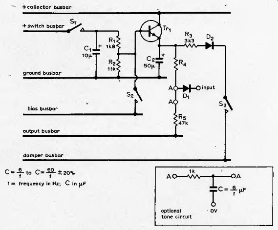
Fig. 4. Key circuit (one of 61) acts as envelope shaper and modulates input
from the dividers to feed amplifier via busbar. The three busbars wired to
the three switches run alongside keyboard switches. Optional tone circuit
was used on the bottom twelve keys of the author's design to make low tones
less harsh.
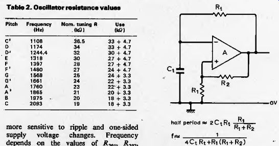
Table 2. Oscillator resistance values.
Oscillator circuits
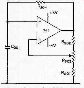
The 12 oscillators use operational amplifiers in a precision relaxation oscillator circuit (Fig. 5). The output of the op-amp switches between nearly the positive and negative supply voltages. When the output has just gone positive, the negative input voltage starts to change positively as charges. When it reaches the positive input voltage, VoR1 (R1+r2) the invering action causes the output to fall negatively, almost instantaneously. The circuit has a bridge configuration which almost eliminates the effect of load and supply voltage, _ At the instant of switching a differential voltage of 2 VrR JiR, + exists at the amplifier inputs, which limits the ratio R., iR 2 that can be, used at the chosen supply voltage with 709 series op-amps (but not 741 types). Sources of drift in the circuit include offset voltage and bias current changes.
Supplies of +5V, -5V were chosen to simplify the power supply and buffer circuits. This has rendered the oscillators more sensitive to ripple and one-sided supply voltage changes. Frequency depends on the values of .R201, J{202, T?204v and Czol, and is set by R1Q2 (Fig. 6). High-stability components are required.
A buffer circuit Rlu., 7V20, is incorporated as the load of the divider input and the discharge current from the top octave key circuits may be as much as 6.6mA, which is more than the op-amp can be guaranteed to drive. The 7493 i.c. divides the oscillator frequency by 16 and has outputs for 2, 4, 8, divisors also. It changes state for an input transition from high to low, and has two reset inputs, one of which must be grounded for operation as a divider or counter. The outputs will sink more than 16mA ample for driving the key circuits.
Eleven of the oscillator and divider circuits are as shown, but for C an overall divisor of 32 is required and so the output -F 16 is wired to the input of another divider stage whose output then feeds low C.
hatf period as 2CtR+ --Ri + Rj
1 4Ct Rt+Ri (Ri + R^)
Fig. 5. Relaxation oscillator uses bridge configuration to keep effects
of load and supply voltage changes to a minimum.
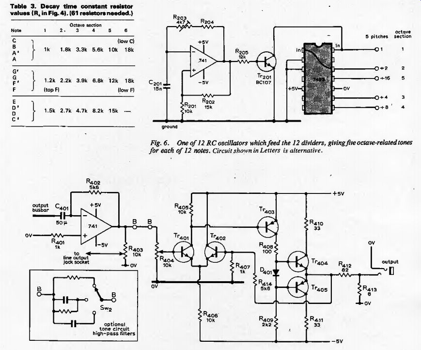
Table 3. Decav time constant resistor values tR., in Fig. 4). (61 resistors
needed.)
Fig. 6. One of 12 RC oscillators which feed the 12 dividers, giving five octave-related tones for each of 12 notes. Circuit shown in Letters is alternative.
Fig. 7. Amplifier accepts inputs from 61 key circuits via output busbar. Discrete-component amplifier can be omitted if headphone operation is not needed.
Summing preamplifier
The summing circuit is a standard op-amp arrangement. Capacitor C_401 (Fig. 7) blocks the DC component of the output, i.e. the C2 voltages which would be summed to about 25V. Resistor R_401 is not mounted on the board but at a suitable point among the key circuits, thereby using the differential inputs to minimize pickup of unwanted signals. The headphone amplifier likewise is a fairly standard discrete-component op-amp with complementary emitter-follower output. It can be readily altered to drive various loads.
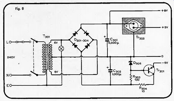
Power supply
The power supply unit (this page) provides regulated voltages of +5V at 600mA -5V at 50mA, an unregulated -1-8V at. 250mA, and a low-voltage a.c. .to light an indicator lamp. The twin full-wave rectifier arrangement produces two "raw" DC supplies with a minimal voltage loss across diodes, A simple discrete component regulator is used for the negative line, and an integrated regulator is used for the positive supply to maximize reliability. The t.t.l. divider circuits may be ruined if a regulator failure causes their supply voltage to exceed 7V. Regulated supplies assist in maintaining the frequency stability of the oscillators.
Busbar lines
A number of wires feed signals and power to all parts of the piano circuitry (Fig. 3.) These wires are for the +5V regulated power line, the -5V regulated line, ground potential, the switch bus fed via a resistor from the unregulated + supply, the output bus, the bias bus and the damper bus.
The bias bus is returned to ground via a rectifier diode and trimming potentiometer in parallel, so that the bus voltage may be finely adjusted. When the sustain pedal is pressed, thus closing a remote switch, the bias, voltage is reduced, cutting off Tr501 whose base is connected to the bias bus. An emitter-follower Tr501 is used to control the damper bus, whose potential is 0.7V below that of Tr501 collector. Therefore when the sustain pedal is depressed, the damper bus potential rises by 5V to +4.3V.
Keyboard
The keyboard used in the prototype is a five-octave plastics-keyed C-C electronic organ keyboard of Italian origin, supplied by Eivins Electronics, Other keyboards may be obtained, e.g. from Harmonics Ltd and from Kimber-Allen, and if these are used some of the cabinet dimensions may have to be altered.
For musical reasons it is most preferable that the keyboard be F-F with low F at 43Hz, I believe that such keyboards may now be obtained to order. With a C-C keyboard, one has the option of modifying it to F-F by cutting away the bottom five notes and re-attaching them at the top of the keyboard.
Converting the C-C keyboard. Unhook the springs from the bottom ends and poke out the pivot wire. Put the keys aside in order. Gut the frame flush with low F and cut off the top C mountings also. Rearrange the C-E portion at the top of the keyboard with the top C (now top F) above it, and repair the saw cuts with sheet metal and self-tapping screws, being sure to get the key spacing exactly right. Replace the keys on the board, threading the pivot wire from the bottom end. A similar operation can be performed on the Kimber-Allen keyboard. If you are at all doubtful about cutting up the keyboard, it would be better to order the F-F version. As the. pitch of the mountings varies over an octave, it is not possible to simply shunt the keys down the board.
--------------
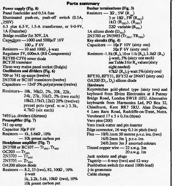
Parts summary
Power supply (Fig. 8)
-------------------------
Part 2--assembling circuits and case
by G. Cowie, B.Sc.
The piano is designed so that the 33-in keyboard will just fit inside its case. There is a metal projection at the low end of the keyboard that must be sawn off flush with low C for the keyboard to fit. The keyboard base plate is used as a chassis for the keying circuitry, and the remaining circuitry is mounted in the upper rear of the case.
Before starting work, you should consider the finish for the case. As described, the case is suitable for finishing with paint, leatherette, or, like the prototype, with Formica. If a Formica-type finish is wanted then a lot of time can be saved by using a plastics-surfaced board for parts 2, 3, 5, 7 and possibly 11 (Fig. 9). Some dimensional changes will be necessary, and parts 4, 5 and 6 must be shortened to 33.1 in. Exposed wood edges may be painted. Wood parts are fastened together by gluing and do welling or nailing.
Start by cutting the wood parts to shape, using a rasp if necessary to trim them to exact size. Parts 2 have notches cut in them to fit parts 4 and 6. Parts 2 should be identical, and this can be checked by clamping them together. It is important that the internal width from front to back is a fraction over 33in (say 33.1 in) otherwise the keyboard will not fit. This dimension is identical to the length of part 3.
The case is deeper from front to back than strictly necessary, and if you do not intend to put anything other than the circuitry described inside the case, you can reduce the front-back dimension by up to three inches. This involves shortening parts 1, 2 and 7.
Case assembly
Begin assembly by gluing and panel-pinning part 1 to part 4. Add parts 2, and dowel part 4 to parts 2. Next attach part 6 with glue and dowels. (Dowelling should be done by drilling one of the parts to be joined and then, holding the parts in their final position, passing the drill through the hole already drilled to drill the mating part to about an inch deep. Spread glue on the dowel and the mating surfaces, place the parts together and knock the dowel fully in.) Part 3 rests on top of part 1 and is fixed to parts 2 by dowelling. Tack parts 3 and 1 together with a few panel pins and fill up the crack with glue and strips of wood. Part 3 has one edge planed off at 45°, and the opposing edge is also planed at 45° to fit against part 1, Part 5, the back panel, should be left slightly oversize until fixed in place. It is more convenient to drill the holes, with a bit and brace, before fixing. Three holes of |-in dia. and two holes for a mains connector and fuse are required, their positions not being critical. Apply glue to mating surfaces and secure the part 5 with panel pins.
At each step in the assembly check that the parts are squared up. If a rear panel of plastics-coated board is used, cut out a neat aperture about 3” x 4” before assembly.
Subsequently the aperture can be closed by a connector panel fixed to the inner surface of part 5. When the lower case assembly is completed set it aside for the glue to harden.
The keyboard is bolted to two metal channel sections 13, which in turn are screwed to the hinged upper half of the case.
In their normal position, parts 13 rest on part 1, touching parts 2, so that they fix the height of the keyboard and its position; ideally 0.5in clear of parts 2.
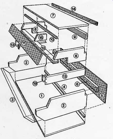
Fig. 9. Top part of the case, comprising nine wood parts
and a front panel, carries the keyboard-bolted to parts 13 with angle brackets-and
lifts to expose wiring about hinge (14.). Parts 16, 17 & 18 are shown
in Fig. 10. Dimensions given in parts list.
Parts 13 are fixed to the vertical front part of the keyboard chassis by two brackets of 0.75 inch angle, 1 1/4-in long. For each fixing, drill two holes in the keyboard chassis and two in parts 13, the last-mentioned being countersunk. A section of flange of each part 13 must be cut away over a length of three inches to clear the top and bottom C actuator slots and the key-switch mounting area behind. (To do this with an ordinary hacksaw cut and file away a portion of the flange so that the hacksaw blade can be got into position to cut away the remaining scrap section with a longitudinal cut.) Bolt the parts 13 in place, with the nuts inside, and place the whole assembly on a flat surface. Make sure that parts 13 are square to the keyboard, and drill at each end of the keyboard, near the springs, a 6BA-dearance hole so that the chassis plate can be bolted to part 13 flange.
Place the assembly inside the lower case to check that it fits without jamming, and decide on the precise position of the keyboard with respect to part 3. If the keyboard is to be well forward, as in the prototype, then the edge of part 3 must be relieved so that the white keys do not strike it. (It is a good idea to put small packing pieces underneath parts 13 as then it will not matter so much if swarf and shavings collect there.)
On looking at the top of the keyboard, there is an obvious transition between the seen and unseen parts of the black eyes. It is important to know the exact horizontal distance (about 11 in) between this point and part 6. This dimension, less 0.05-in clearance, less the hinge thickness, less the thickness of any laminate finish on part 11, is the front-to-back depth of the upper case assembly. If a mistake is made then either the black keys will strike on part 11 or there will be an unsightly gap.
==================
Notes on components
The pieces of Veroboard for the key circuits boards are 17 x 5 in, as advertised by various suppliers, but which does not appear in Vero's current lists.
If the board specified cannot be obtained, a slightly longer and narrower board could be used instead.
The resistors used on the keying boards are |-watt because larger resistors would be more difficult to fit in the space available. Similarly the diodes should not be bigger than the Do 7 size, which is about 0.3-in long excluding leads.
"Untested" silicon signal diodes were used in the prototype, and proved to be satisfactory. They are very cheap, but it is necessary to test them with an ohmmeter, both to weed out a few faulty diodes from the batch and also to determine the polarity of each diode. The ohm-meter will give a reading characteristic of a silicon junction when its red lead is applied to the cathode (+) end the diode and its black lead to the other end.
"Untested" transistors may be used to save money but in my experience they are less satisfactory than cheap diodes.
It is to be expected that nearly ail the batch wilt be usable for something, but that half will be leaky with a tendency to deteriorate. They should be tested as thoroughly as possible to ensure that the transistors used have a gain of greater than 40 at 100mA and a leakage of less than a micro-amp or so. The transistors specified are a medium-power type, and low-power transistors should not be substituted in the key circuits. The dividers and op-amps must be good devices, not rejects. They can be bought nowadays for little more than 55p and 25p each, respectively. In the remainder of the circuitry the choice of semiconductor devices is not critical.
Capacitance values for the key circuit capacitors C1, C2 should be adhered to as closely as possible. Voltage ratings are low to minimize bulk and cost, but are not critical provided that C1 is 10V or more and C, is 6V or more. Tantalum capacitors are preferred as the tolerance on capacitance values is closer. On the other hand it is not known what effect the better power factor of the tantalum capacitors (without series resistors) will have on the life of contacts S_ and the tantalum capacitors are more expensive.
Aluminum electrolytic capacitors performed adequately in practice. Essentially the question is one of initial cost versus reliability.
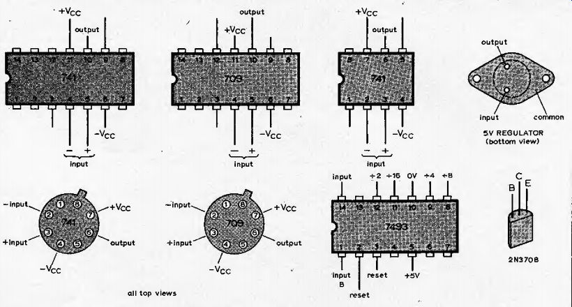
The operational amplifier used for the summing preamplifier should be a 741 as this type is internally compensated. As no compensation is needed for the oscillator op-amps the slightly cheaper 709 type can be used instead. Lead connections for several packages were given in part 1.
==================
--- Footswitch for sustain action is simply a push-button switch embedded in a wood block.
Lay the parts of the upper case, 7-12, together to check that they form a structure of the right size when fitted together. Parts 8 rest on parts 13, and part 7 placed on top should be flush with the top of the lower case. Make sure the gap between pieces 12 and 13 is sufficient to clear the keyboard.
Glue and nail parts 7 and 9 together, and add parts 8, dowelling it to part 9 and dowelling or nailing them to part 7. Plane the front edge of part 12 to a 30° angle and fix it to parts 8 with dowels. Add part 15 with dowels to give some central support to piece 12. Leave this assembly to dry. Check that the upper case assembly fits into the lower case without jamming or leaving an excessive gap at the sides.
Part 11 is thin so that the mains on/off switch and any extra controls can be mounted on it. Fit it by relieving the front of part 7 at 30" or by relieving part 11, leaving some gap to be filled or concealed, the lower edge of part 11 should be relieved at 30® on the inner side. Use glass paper or a sanding disc to smooth down the mating surfaces for part 1). Attach part 11 with glue and a few panel pins. Use the parts 10, suitably shaped, and some glue to fill and strengthen the join between parts 7 and 11.
Put the assembly aside to dry upside-down so that parts 10 will stay in place. (At this stage the upper and lower case halves may be painted on the inner surfaces.) Attach two lengths of j-in or f-in square wood (parts 16 and 17, Fig. 10) to the keyboard chassis plate to act as bearers for the key circuit boards, which are to be 7/8 to 1-in below the main plate. Fix part 16 by woodscrews to the front vertical plate, which must be drilled for four fixing holes. Secure part 17 by woodscrews at its ends to parts 13; a countersunk, hole is required in each part 13. Drill the main plate in two places by the springs, about one-third and two thirds of the length of the board, so that packing pieces can be fixed in place to stiffen part 17. The keys scratch easily so protect them during drilling.
The desired surface finish is most conveniently applied to the outside of the upper and lower case at this stage. In the prototype all visible surfaces are white Formica except for the inner surfaces of parts 2 and the top edge of part 3, which are black, Various accessories are next fitted to the case. Fit the three jack sockets, the mains connector socket, and the mains fuseholder to the rear panel. Next fit the mains switch and indicator lamp to the front panel.
Attach the piano hinge to. the upper case, with the axis rod above the top surface.
Arrange the upper case in the fully open position, supported on a block, and screw the hinge to the lower c .se. This is trickier than it seems and it is best to put in two small screws first so that the assembly can be closed to check whether it is all lined up and fits properly. If all is well then the hinge may be securely fastened by y-in countersunk-head brass screws.
Screw parts 13 to parts 8, thereby fixing the keyboard into the upper part of the case. Screw an eyelet into each side of the case, inside, next to part 3, and provide a similar fixing on the keyboard chassis. Permanently attach two restraining cords to hold the upper case open in a suitable position for working inside. Check that the assembly still closes,. Fit the case carrying handle and add metal ties between parts 3 and 1 at the handle location. Two large self-tapping screws are used to hold the case closed. Turn the case upside-down and drill two holes near the front of the case in such a position that they pass through the flange of part 13. These holes must be of the root diameter of the self-tapping screw. Next drill the wood to the clearance diameter, grease the screws and screw them into place by repeatedly making one turn in and half a turn out.
Circuit assembly
In one sense the assembly work is very, simple as there are only five major circuits involved, none of which has more than a dozen components. There is, on the other hand, a great deal of work to be done, and very boring and repetitious work at that.
To give some idea of the time involved, fitting 60 components on boards will take 1.25 to 1.5 hours from unpacking to checking the soldered joints, and putting in the 183 key wires will take at least a day. Clean soldering and general neatness are very important, greatly increasing the chances that the circuitry will work as intended.
Make up the power supply, oscillators, and amplifiers first, so they can then be used to test the key circuits.
No detailed assembly is shown for the power supply as it is a simple wired unit and the original was made from junk. For safety it is best to make the power supply on a metal baseplate and completely enclose it in an earthed metal case. Mount the +5-V regulator on a small heatsink of j^-in thick aluminum forming the lid of the case. As the case of the regulator forms its 0-V connection it should be isolated from the heatsink with the standard kit of mica washer etc, so that the 0-V line can be floated or grounded as necessary. Make sure that no live terminal is within j-in of anything on the low-voltage side. Earth any metal parts of the on/off switch showing on the front panel, as well as the metal case of the power supply. Mount the unit in the lower left hand part of the case.
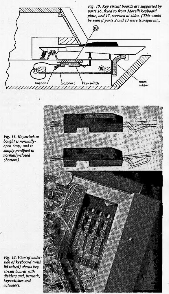
Fig. 10. Key circuit hoards are supported by parts 16, fixed to front Morelli
keyboard plate, and 17, screwed at sides. (This would be seen if parts 2
and 13 were transparent.)
Fig. 11. Keyswitch as bought is normally open (top) and is simply modified to normally-closed (bottom).
Fig. 12. View of underside of keyboard ( with lid raised) shows key circuit boards with dividers and, beneath, key switches and actuators.
Keyswitch modification
The key switches as bought are of the triple normally-open type, not normally-closed as required. This is of no consequence as it is a simple matter to hook the bent wire of each pair around the straight wire, so that the switch becomes normally-closed (Fig. 11). It is less easy to arrange for the contacts to open in the correct sequence. In the prototype this was done by mounting the keyswitches and then bending both wires of all three pairs until the desired result was achieved. As the differential between S, and S2 opening is fairly critical, and there are 366 wires in ail, this was tedious. 1 therefore devised a procedure which is not only less laborious but should give more satisfactory results.
Under each key is a plastics actuator rod capped by a rubber boot which is designed to push the straight key switch wires (see Figs 12 & 13). A notch 0.1-in deep must be effectively produced at one side of each pusher, and the simplest way of achieving this seems to be to stick a tiny square of plastics sheet, not to the rubber boot, but to the two wires that must move first (Fig. 13). This should be 0.10-in (2.5-mm) thick, and about 0.15-in (4-mm) square. One side of the. keyswitches has a large rectangular notch which exposes the wires. This is the visible side, and the opposite side is the mounting, side. The plastics squares of course go on the mounting side of the wires.
Simplest way to attach, them is to apply a little glue with a matchstick to the ends of the two wires, touch them on the square to pick it up, adjust it carefully for position, and leave the assembly upside-down to set.
Contact adhesive should stick most materials; alternatively a solvent adhesive or Araldite could be used.
The keyswitches must be mounted on a spacing piece (part 18, Fig. 10) stuck to the main plate of the keyboard chassis. The thickness of the spacer must be determined before the keyswitches are mounted. Find a piece of packing which wilt support one of the keyswitches in an operating position so that the rubber actuator is almost touching the plastics pad. This should ensure that when the key is pressed, the actuator opens first two contacts almost together, and the third before reaching the end of the travel (the differential is 0.01in). A piece or pieces of packing, preferably of plastics, two inches wide and in all 33-in long are stuck down with contact adhesive, and the keyswitches are stuck to this with contact adhesive. They should be as far back as possible consistent with correct operation; and they can be placed with sufficient accuracy by hand.
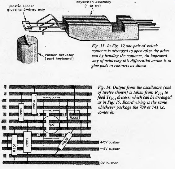
Fig. 13. In fig. 12 one pair of switch contacts is arranged to open after
the other two by bending the contacts. An improved way of achieving this
differential action is to glue pads to contacts as shown.
Fig. 14. Output from the oscillators (one of twelve shown) is taken from R205; t0 feed Tr201, drivers, which can he arranged as in Fig. 15. Board wiring is the same whichever package the 709 or 741 i.e. comes in.
Oscillator assembly
The twelve oscillators (Fig, 14) are identical except for the tuning resistors (see Table 3 in part 1). The frequencies used depend on whether a C-C or F-F keyboard is chosen; 2093 to 1108 Hz and 1397 to 739.8Hz respectively.
The layout shown in Fig. 15 is designed to enable six oscillators, and six buffer transistors to be assembled on a 2.5 x 5 x 0.1 in pitch Veroboard. In the prototype two of these were mounted on plug-in carriers so that the oscillators could be removed easily for tuning and repairs, but to make things as simple as possible I recommend that all twelve oscillators and the buffer transistors be mounted on a piece of Veroboard of at least 5 x 5.5 in which is wired for plugging into a suitable edge connector with a minimum of 16 ways (that is twelve outputs, three' power lines, and a space for a polarizing/locating key). Use the layout given, placing the oscillators in four rows of three. The order is not important, but it is helpful if they are arranged on the board in strict alphabetical order. Break the copper tracks where shown with a Vero spot face cutter or drill. All tracks should be broken between oscillators except the three power lines, and the four tracks under the i.e. must also be broken, Wire resistor R205 to the buffer transistor.
The integrated circuits may be either the 709 or the 741; see part 1 for pin connections. Note that the twelfth or eighth pin is not connected in the 741 but is internally connected in the 709 and so no connection must be made to it. Either skeleton or button-type preset pots may be used, the skeleton type being easier to mount. Resistors R201 to R104 should be 2%, 0.5-watt types, and the capacitors polystyrene or polyester. The component leads may be left a little long to stand them off the board. The presets form a small part only of the tuning resistance so their stability is less important: Mount the edge-connector of the oscillators in the upper right part of the case, and arrange a clip to hold the free end of the oscillator board.
Amplifier assembly
The summing preamplifier and headphone amplifier (Figs 16 & 17) can both he assembled on a 2.5 x 5 in piece of Veroboard, of 0.1-in pitch, and arranged to plug into a suitable edge-connector. An internal connection must .be made between R404 and the input of the headphone amplifier, and the external connections are the three power lines, two inputs, low level output, and headphone output. A 741 op-amp must be used in this circuit.
Mount the edge-connector for this board in the upper right part of the case, together with a 12-way tagstrip.
Wire the three power lines to the tagstrip, using fairly thick stranded wire f24/0.2mni). Connect a lead for the -i-8-V line from the power supply to the tagstrip, and check that none of the wires can be trapped when the case is closed. Mount the dropper resistors RJ06 and R507 on the tagstrip. Mount the components Rjoi-j, Dsou 7>5()1/2 on the tagstrip, making connections to the power lines. Two of the tags are also terminals for the bias and damper lines. Wire the amplifier edge-connector to the two output sockets. The low-level socket should be wired conventionally, but the headphone socket should be a three-way socket with the 0-V line wired to the middle contact and the signal to the inner contact, so that normal connection is made to a two-way jack, but the coils of stereo headphones are connected in series. Wire the sustain pedal connection from the tagstrip to the sustain pedal socket. Connect power lines to the oscillator and 1 amplifier edge-connectors from the tagstrip. If the power supply uses a 9-volt transformer then /f507 must be about 18 ohms to drop the raw direct voltage to the 8V required for the switch busbar, and for a 6.3-volt transformer it must be about 3 ohms.
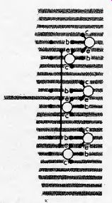
Fig: 15. Twelve top-octave driver transistors (Tr20l, six shown) can he
arranged to enable six oscillators and drivers to he accommodated on x Sin
Veroboard or, preferably, all twelve on a 5 v. Sin hoard.
Key circuit assembly
The key circuits are assembled on two. large pieces of 0.1-jn pitch Veroboard, one 5x 15in, the other, containing the odd key circuit, 5 x i6jin. The overall length is calculated to be just less than the distance between parts 13 flanges. The 12 groups of key circuits are identical, and the 61 key circuits are themselves identical save for the connections of diode D. The assembly details are given in Fig. 18 which shows the divider and the top key circuit. The whole: group should be exactly five inches long, the pitch of the key circuits being 0.9m.
Mark each circuit board with two rows of three 2^ x 5in rectangles, using a scriber, Mark within these the areas occupied by the key circuits. Each occupies a width of eight holes, the boundaries between key circuits falling, on the ninth rows of holes where several tracks must be cut to electrically isolate the circuits. Fit the divider ICs in their correct positions, at the top of each rectangle and one hole from the left-hand edge. Use Veroboard pins or some cheaper equivalent to attach the key wires, three to each key circuit, At the assembly is quite a large operation, much time will be saved if it is approached methodically, for instance by taking 61 components (e.g. /i3), bending all the leads, fitting to the board, bending the leads flush with the tracking, clipping the leads to 0.1 in from hole, and then soldering.
Each group of key circuits must be assigned to a letter, C, A etc.. and the resistors /?4. fitted, following Table 3; The lowest values go with the highest pitch notes, and so the key circuit nearest the divider will have R4 of 1k, i .2k or i .5k (mult. by 1.25 for USD ) £l. The positions of diodes Dl vary; in the no. 1 key circuit the cathode goes to track I (pin 14 of i.e.); in no. 2 to track 3 (pin 12); in no. 3 to track 6 (pin 9); in no. 4 to track 7 (pin 8) and in no. 5 to track 4 (pin 11). The lowest pitch key circuit takes the form of a small 13th letter-group, in physical arrangement. It fits on the extra )^-in of board next to the C letter-group.
The divider could be almost any t.t.l. flipflop but 1 recommend a 7493, mounted on a dual in-line socket so that it can be changed easily. The connections are easily deduced; pin 14 is wired to track 4 of preceding stage, D, cathode goes to track 3.
Lines for +5-V, 0-V, output, and collector busbars run the length of each board Three tracks should be commoned for the ground busbar to reduce the resistance.
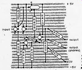
Fig. 16. Summing preamplifier and headphone amplifier (Fig. 17) can he included
on the same board?

Fig. 17. Headphone amplifier, together with R404, could be omitted if an
external amplifier is Used. ?
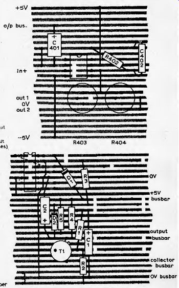
Fig. 18. Layout of one divider and key circuit.
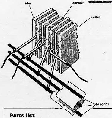
Fig. 19. Three busbars alongside the keyswitches are insulated by tape,
the "switch" busbar being soldered and insulated first.
Outputs from divider feed four similar (except for D, position) key circuits alongside that shown.
(Thirteenth divider feeds only one key circuit). Two large hoards hear 61 key circuits and 13 dividers.
In the five key circuits related to any one divider, uppermost wire of D, connects to different i.e. terminals or tracks (see text). A minor modification to this board is suggested in part 3.
--------------------p94
Parts list
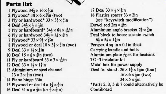
---------------------
Key wiring
Six wires about j-in long extend from the back of each keyswitch (Fig. 19). Bend down the extreme right-hand wire of each switch (looking from the rear), and solder to them a bare tinned-copper wire of about 22 s.w.g. Inspect this work and cover the wire (switch busbar) with a length of adhesive tape. Do the same for the third wire from the right (left, as shown), and cover the damper busbar with tape. The third, bias, busbar should be of slightly thicker wire, and is soldered to the gold wires as shown. The bias contacts are the pair that open last. Bend the remaining gold wires upwards and outwards to make it easier to connect the flex wires.
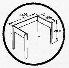
Fig. 20. Simple stand for the piano can he made from deal.
To mount the two key circuit boards, use six small nails, bent over at 45°, in part 17, on which the boards rest. To hold the boards while the case is closed, drill four holes in part 16 to take retaining screws with large washers, which overlap the boards.
Key wiring must be done with miniature stranded flex wire. Connect a wire to the switch contact, top C. Pass the wire through the gap between part 17 and the keyboard plate and lead it along part 17, then up through a right angle towards the connecting point-the pin on track 11 of the top C key circuit. Similarly, connect the damper wire to the pin on track 2, and the bias wire to the pin on track 18. Place cable ties at intervals along part 17 to hold the wires and tie wires together to the board in groups of six where they pass up over the lower edge of the boards.
When several keys have been wired up check whether the system works. Wire the bias, switch, and damper busbars to the tagstrip, and connect the ground 0-V line to each key circuit board. Check that the power supply delivers the correct voltages and connect the + 5-V and collector busbar lines to both boards. Connect oscillator signal lines for the letter-groups in use, plug in headphones, connect the output busbar to the amplifiers, temporarily ground the positive input of the summing preamplifier, plug in the oscillators and amplifiers, and switch on. If the wired keys do not work look for faults as detailed later (part 3). The remaining key wires may be put in when you are satisfied that the system is more or less in working order. The wires should be cut a little long, leaving about two inches of slack.
Part 3--tuning the touch-sensitive design, an MOS master oscillator and other optional circuits.
by G. Cowie, B.Sc.
When you have completed the wiring of the piano the remaining work is to commission and tune it. In a project of this complexity it is inevitable that a number of faults and wiring errors will occur and the purpose of the commissioning stage is to weed these out and make various adjustment.
Start by applying power and making the following voltage checks.
supply busbars, 0V, +5V, - 5V
collector busbar, about 0.5V
switch busbar (after ) 7 to 8V
damper busbar, about -0.4V
bias busbar, about +0.8V
output busbar, + 0.4V.
Turn both potentiometers on the amplifier board to mid-position, and check that the pre-amp and amplifier outputs are about 0V before proceeding further.
Connect headphones or an audio amplifier to one of the output sockets, A hiss and probably some whistles will be audible but ignore this for the moment. If nothing is heard, check the output amplifier and preamplifier. Check that a note is heard when each key is struck, and that the pitches are more or less in the right order, bearing in mind that the oscillators are not tuned.
The system is organized in such a way that with a little thought any fault evident can be localized to one or two connecting lines, or a few components either in a letter-group or in a key circuit. Absence of signal from a key circuit will most likely he caused by absence of input signal, resulting from a reversed diode, or a mis-connection at a divider or oscillator. Whistles, traceable by their pitch, will be caused by leaky transistors or bias connection faults, or damper faults. Faint notes will be caused by collector open-circuits. Open or bent key-switches will show up as faults. The sort of defects to look for are missing wires, missing links near ICs, bad soldered joints, assembly mistakes, solder bridges, parts touching where they should not touch, tracks not cut.
It may possibly be necessary to add power supply decoupling capacitors on the various circuit boards.
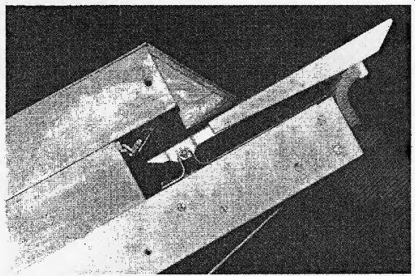
Fig. 21. To simulate the inertial load of the keying action, a piece of
foam plastics material is inserted between the key undersides and the lower
flange on the keyboard chassis.
If the power supply uses a 9-volt transformer, R507 must be increased to about 18 ohms to drop the raw direct voltage to the 8V required for the switch busbar.
Check that each note ceases when its key is released, then short-circuit the sustain pedal socket and check that the notes now are sustained after the keys are released.
When all the circuits have been made to work, several finer adjustments can be made. Disconnect the positive-signal input of the summing preamplifier from 0V and extend it from the edge-connector with about 30in of flex wire. Solder the wire to the end of resistor, and then attach R_401 the 0-V busbar on the key circuit boards, in a position that gives minimum pick-up of unwanted signals. Run the positive signal lead alongside the output busbar as far as possible. It is important to arrange the 0-V lines carefully, to minimize stray signals. Connect a lead directly between the key circuits 0-V busbar and the preamplifier ground. Hiss should be inaudible while the instrument is being played.
If there is still too much background hiss then reduce the value of R501, until the hiss is reduced to a low level. If the resistance is reduced too much there will be an undesirable effect whereby the keys refuse to work at all when pressed down very slowly.
If the damper action is felt to be too abrupt then the potential of the damper bus can be raised by connecting a resistance of a few hundred ohms in series with R5o2and connecting the base of Tr5al to the junction of the resistors.
If the action of any of the keys is noticeably different from that of the majority, the cause should be looked for and put right, otherwise it will be a permanent irritation when playing the instrument.
It is important to alter the light spring-loaded feel of the keys if the touch-sensitive action is to be satisfactory. The ideal arrangement would compromise 61 viscous dampers simulating inertial loads, but in the prototype a much simpler device was adopted which proved to give an acceptable result.
Cut a piece of flexible foam plastics material to dimensions of 2 x | x 33in. If a piece 33-in long cannot be found then use shorter lengths. Push this into place between the white key undersides and the lower flange on the key chassis (see Figs 10 & 21).
In this position the black keys will rub against the foam and the white keys will deform it so that a drag is felt on the keys. Key action wilt not be satisfactory unless this is done.
Tuning
The easiest and most satisfactory way of tuning the oscillators is to remove the oscillator board from the instrument and take it to a laboratory which has. a suitable digital timer/counter and DC power supplies. The oscillators should be connected to a +5-V supply. They should be monitored at the op-amp output where a clean square wave is present. It is advisable to use an oscilloscope to look at the waveforms and see that all is well.
The oscillators can then be adjusted to the frequencies in Table 1 (part 1) by the tuning pots to an accuracy of +2 parts in 1000. If an adjustment is outside the span of the potentiometers it will be necessary to add padding resistors. Label the oscillators after they are set so that they can be wired up without confusion.
If you do not have access to the above equipment, either through work or friends, the oscillators must be tuned in situ, by ear.
The person doing the tuning must have a musical ear and be equipped with an "A" tuning fork. The piano case must be open so that the tuning pots are accessible. Tune the A group of notes against the fork. Notes F are next tuned against the A; the interval should be a major third. Next tune C by means of the major chord F-A-C, and adjust F again if necessary. Use C to tune E, the interval being a major third, then tune G in the major chord C-E-G. Use G to tune B (major third) then tune D using the major chord G-B-D. This completes the white notes.
Tune E_b using the chord F-A-C-E and using the major chord Ej-G-Bb. Tune Afc. using the chord Bj-D-F-A j or the major third C-Ab. Tune F# using the major third D-F'-. Tune using the major chord A-G*-E. You will probably need to go over the process several times. Fortunately the electronic piano is much easier to tune than a string piano, which has over two hundred adjustment points.
If you use a m.o;s top-octave synthesizer i.e., only one tuning adjustment will be necessary, and will take only a few minutes (see later).
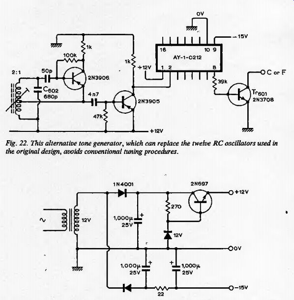
Fig. 22. This alternative tone generator, which can replace the twelve RC
oscillators used in the original design, avoids conventional tuning procedures.
Fig. 23. Power unit to provide a the preamplifier and headphone Fig. 8 (part 1) can be omitted.
Circuit options
On the key circuit boards (Fig. 18), remove the links between track 24, to which resistors R7 are grounded, and track 23. Link the tracks by a silicon signal diode on each board, connecting the cathodes to track 23. This modification is based on work done after the prototype was completed, and if carried out should slightly improve the keying action at the "soft" end of the dynamic range.
The prototype is a basic instrument in that no attempt is made to modify the inherent tone of its working waveform, except by a single low-pass filter. It is purely by coincidence and the laws of physics that it sounds as much like a harpsichord as anything. If this tone is not acceptable then additional wave-shaping can be added fairly easily. There is room on the keying boards to fit a low-pass filter between D1 and R5.1 fitted filters on the 16 lowest notes to take harshness out, with resistors of 10 kO and capacitors of 20nF. More complex circuits could be built on a separate board, linked by a 61-way cable form.
A power amplifier could be fitted inside the case, but as this would need a separate power supply it does not seem worthwhile.
Similarly, loudspeakers could be fitted in the case, but as fairly large speakers will be needed to reproduce the bass notes properly, and as the case is not designed as a loudspeaker enclosure, this is not recommended; A tremolo circuit could easily be fitted after the preamplifier. It is hot known whether vibrato can be applied to the oscillators successfully, and anyway this seems inappropriate.
The headphone amplifier could be replaced by an integrated circuit. The MFC 4000 is a cheap i.e. designed for the output stage of transistor portable radios.
A board containing twelve L-C oscillators could be made as a plug-in replacement, but as discussed in part 1, relaxation oscillators are preferred for several reasons.
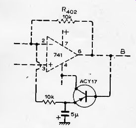
Fig. 24. Optional "anti-thump" circuit comprises three additional
components to the circuit of Fig. 7.
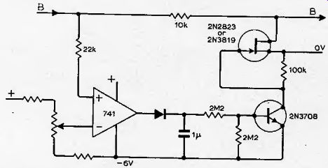
Fig. 25. Use this squelch circuit to eliminate "hiss" due to leakage
currents (hat may be evident during standby. Suitable values for potential
divider are 10-kO and 5-kO for the preset resistor.
Amplification
For low-power amplification, as for practicing, almost any amplifier and speaker can be used provided that the speaker is of adequate size, A speaker of 8 in diameter should give good results, bearing in mind that the bass notes have more fundamental than those of an acoustic piano. If high powers are wanted then it is essential to use heavy-duty speakers of the type used for electric guitars. The speakers should have a higher nominal rating than the amplifier otherwise the percussive piano waveform will probably damage them.
A standard volume control pedal may be bought and fitted between the piano and amplifier, and R403 preset to a suitable level.
MOS master tone generator
The RF oscillator and AY-0212 ohm master tone generator replace twelve oscillators (Fig. 22). The frequencies generated are within 0.1% of an equal-temperament scale, so the piano will work perfectly well without being tuned at all! It can easily be tuned against another instrument or a frequency counter if desired. It would be possible to arrange the circuit for rapid transposing; this is impracticable with twelve oscillator generators. It is still necessary to have twelve interface circuits to the t.t.l. dividers.
An extra power supply is necessary also.
The circuit shown (Fig. 23) provides regulated + 12V and smoothed unregulated 15V for the AY-1-0212. The --5V supply of the original piano design is omitted. The preamplifier and headphone amplifier should be powered from the + 12V, --15V power supply.
A coil of the 470kHz, IF type, with a 2:1 turns ratio is needed. It may be necessary to change C60 2 to get the frequency into adjustment range of the ferrite screw core. The circuit will oscillate with any coil of about the right turns ratio.
The AY-1-0212 will stand a certain amount of abuse but should nevertheless be treated with care. It should be mounted in a 16-pin dual in-line socket. The one-off price is about (mult. by 1.25 for USD ) £5.90. A Veroboard of 3 x4m should give ample room for the oscillator, i.e. and the transistor/resistor array. It is advisable to bring the connections out at the edge of the board in scale order; the i.e. outputs are in a random order.
If high-frequency noise causes trouble on the lower octaves, additional power line fitter capacitors should be fitted on the circuit board, or In F capacitors can be fitted at the 7>601 collectors or bases.
Squelch and anti-thump circuits Some degree of "thump" will always be present where waveforms are not generated symmetrically about ground potential. Fig. 24 shows the anti-thump circuit now fitted in the prototype.
Hiss due to leakage though the reversed-biased diodes D1 is very low, but can be completely eliminated by the "squelch" circuit of Fig. 25. Connect between points B-B in Fig. 7.
---------------
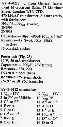
Parts for MOS tone generator AY-1-0212 i.e. from General Instrument Microcircuit Sales, 57 Mortimer Street, London WIN 7TD. 470-kHz IF transformer, 2; 1 turns ratio, with ferrite core 2N3708-7>601 (twelve) 2N3906 2N3905 Capacitors-50pF, 680pF (C602), 4.7nF Resistors-Ik (two), 100k, 39kFl (twelve)
16-pin d.i.J. socket Power unit (Fig. 23)
12-V, 50-mA transformer Capacitors-100 OpF, 25 V (three)
Resistors-270, 22Q IN47001 diodes (two)
BZYS8-CI2V zener diode 2N697 or BFY52 transistor
-----
---------------
Letters to the Editor
Tuning electronic pianos
Readers who are tempted to construct the novel design of electronic piano by G. Cowie, and who try to use the tuning method outlined in the third part of his article (May), will find themselves faced with a very difficult task. Tuning any instrument to equal temperament is not easy, but the job is straightforward, if a little arduous, if the method used by professional pianoand organ-tuners is employed.
The main difficulty arises because the major third is such an imprecise interval. An instrumentalist who can vary the pitch of his instrument (a violinist, for example) will say that he varies the interval of his major thirds (and minor ones, for that matter) according to the mood and tension of the music; yet the interval still sounds in tune. The same cannot be said of the mathematically defined intervals of an octave, fifth or fourth. I put these intervals in that order deliberately, because we can tolerate mis-tuning least in the octave, more so in the fifth, and most in intervals like the third, sixth, second and seventh.
This suggests that we should tune a scale by means of the intervals to which the ear is most acutely sensitive, the octave (I am neglecting the unison, since it is not relevant to laying a scale) and fifths and fourths. This sounds simple enough, but this is where the arduous part comes in.
Because in the Western world we are used to music in dodecaphonic scales (containing twelve intervals) we like to be able to use these intervals freely to construct scales starting on any key-note. It is also convenient to be able to modulate from key to key at will without losing proper tuning, and herein lies the problem. A scale of C major, for example, constructed mathematically by using the exact ratios of the octave (1:2) and the fifth (2:3) has twelve intervals which are. not all equal, and when these are used in other keys, the different sized intervals occur in the wrong places, making the scale out of tune. In equal temperament, all intervals are theoretically made equal. Like George Orwell's animals, some turn out, in practice, to be more equal than others, but as an ideal to aim for, it is satisfactory.
In order to make the intervals equal, the intervals are "bent" slightly, the fifths being made slightly flat and the fourths slightly'sharp. Octaves are of course tuned exactly. Around middle C, the amount of this flattening or sharpening is a little less than one beat per second on average, and takes a careful ear to hear and quantify it.
It is easiest to notice if the interval is first tuned exactly (no beats apparent) and then narrowed or widened slightly accordingly.
The method, then, is as follows: tune A (440Hz) exactly with a fork; take the A below middle C (which the divider circuits have tuned for you) tune up to E, up to B, down to F sharp, down to C sharp, up to G sharp, down to D sharp, up to A sharp (B flat), down to F. down to C, up to G, down to D, and if you are lucky, up to A. The first time round, you will probably find you have overdone the interval "bending", but work back in the opposite direction and adjust slightly until you have laid a perfect, equally tempered scale, then celebrate by playing the entire 48 Preludes and Fugues by J. S. Bach, written for just such a keyboard instrument.
Interested readers can find an excellent article on tuning and temperament in Percy Scholes' Oxford Companion to Music, which gives more details than I can.
David K. Taylor, Charlbury, Oxford.
Tuning the electronic piano
I would like to suggest the following method of tuning any locked-divider electronic polyphonic keyboard instrument.
1. Ensure vibrators or tremulants are "off". Tune middle A to 440Hz, using a fork or BBC test tone transmission.
2. Tune the D below so that it sounds a perfect fifth (zero beat) with the A440. (This should be easily recognized as the commonly heard violin tuning procedure.)
3. Sharpen the D (increase frequency) until it beats with the A at approximately 1 beat per second.
4. Now play the D and the G below it and tune the latter (first to a perfect fifth, then sharpened to 1 beat per sec.).
5. Continue sounding the G one octave above (392) and tune the C below in like manner.
6. Confine the sequences to the middle octaves (by jumping up one octave as required) and carry on tuning in fifths (adjusting the lower note each time) until the final interval is reached, which is E (659) sounded with the fifth below (your original A440).
This should sound like the other intervals (a perfect fifth slightly diminished). The musical reason for diminishing each interval is simply that all modern keyboard instruments are "equal temperament" tuned so that they can be played in any key.
To prove the point; if the instrument is tuned in fifths as described without diminishing each interval the final check interval (E to A) will be so diminished as to sound appalling!
For greater precision, if the instrument can be made to sustain, the beats can be counted over 10 seconds, as per the table given in the interesting book by Richard H. Dorf, Electronic Musical Instruments.
Kenneth Palmer, Kensal Rise, London.
Electronic piano design
I would like to reassure actual or potential constructors who may have been disturbed by Mr Mitchell's letter in the August issue.
The reliability and objectivity of Mr. Mitchell's remarks leave something to be desired. He refers, without being specific, to "considerable circuit duplication". Now it should be clearly understood that while the piano does contain many duplicated circuits, none of these is redundant.
Electronic pianos and organs can be designed along very much the same lines; the main differences being in the key circuits. Now in a polyphonic instrument (and any worth-while instrument must be polyphonic) each key must have an entirely separate piece of circuitry associated with it. In an organ these circuits are quite simple, but in a piano they are not, neither do they lend themselves to total integration.
On the subject of cost, it should be pointed out that the electronics represent only half of the total cost of the project.
It does not seem to be possible to significantly cut the cost of the electronics even by a major redesign; they are already very simple and use cheap components.
There are only about three possible realizations of the oscillator section that are at ail likely to be satisfactory in terms of frequency stability; these are LC oscillators, RC oscillators using high-gain op-amps, and full-octave synthesizers driven by a single oscillator. See the May 1974 Wireless World pp. 143-5 for details of the latter. Special ICs of the "555" type probably are not stable enough. The most costly solution, the full-octave synthesizer i.e., is probably the best. The necessary buffers cost little, I hope that those readers who ordered demonstration cassettes found them helpful;. they were of course intended to demonstrate the characteristic "electronic piano" timbre which differs somewhat from acoustic piano sound. My apologies are extended to anyone who was expecting anything musical; nothing of the sort was promised! Geoff Cowie, London, N10.
Electronic piano design
May I suggest an improvement to G. Cowie's electronic piano (March-May issues)? My experience of his ivC relaxation oscillators has been that they are potentially extremely stable, but suffer from variations in contact resistance of the preset.
The problem can be minimized by a simple rearrangement of components as shown in the diagram. Any change in contact resistance is to be compared with the input resistance of the 741, not R 2m.
Since the input resistance of a 741 is typically 1MQ an increase in stability greater than an order of magnitude can be expected.
The formula for frequency of oscillation should be
/= Ri E R 2 M. Walne, Brighouse, Yorks.
and not as published.