A five-channel unit using active band-pass filters
New ideas in tone controls have appeared in the last few years which improve or supplement bass and treble controls, which are usually of the Baxandall type.
If the function of these controls is clearly understood, a fairly flexible amplitude frequency response curve can be built up. However, an easier and more versatile method of building a desired response is to use a number of overlapping, variable gain, frequency channels, spaced evenly throughout the audio spectrum. By using linear slider potentiometers, the control panel presentation can be made to resemble a response against frequency graph. In this form the system is sometimes called a "graphic equalizer". The unit which will be described for construction has five channels with center frequencies of 50Hz, 200Hz, 800Hz, 3.2kHz and 12.5 kHz.
The linear slider potentiometers used give a control range of ± 12dB, The designed signal level for normal use is around 0-dbm (approximately 800 mV), a level matching most modern amplifier and recording equipment inputs.
Negative feedback system
The usual method of obtaining a multichannel response is by using an LC bandpass filter and gain control for each channel.
The range of inductance needed to cover the ten octaves or so of the audio band makes the filters expensive and unattractive. In addition, much trimming is normally needed to obtain a basically flat response, due to crossover interactions between channels.
Negative feedback methods offer many advantages, such as reduced noise and distortion and accurate gain setting using potentiometers of linear law. In the case of the multichannel system, the filter specification may be greatly relaxed, and trimming can normally be eliminated.
A block diagram of this type of system is given in Fig. 1. At the center frequency of a channel, and assuming no interaction between channels:
1K. \Vin\ = K/Rb
If a simple tuned circuit bandpass filter is used, in order to cross over evenly between channels the Q value should be: _/2^x/(2^x-1), where x is the channel spacing in octaves. In a negative feedback system this is not critical and the value of Q can be raised to reduce the interaction, the penalty being a rise in noise at the crossover points. Error in the center frequency of a filter has a similar effect; as a guide, approximately 1.5dB increase in noise is produced by 50% Q error, or 15x% error in center frequency.
At a first glance it would seem desirable to make the first and last filters low and high pass respectively, but in actual fact this response is produced in a negative feedback loop using only bandpass filters. The penalty is increased noise again, but this time well outside the audio range, assuming a reasonable choice of channel frequencies has been made. Using only bandpass filters simplifies the system since only one basic filter type is required. The design of this network will now be considered.
----------
Performance of the five-channel tone control
3-dB bandwidth at 1V RMS signal level, controls flat: 8Hz-30kHz distortion at IV RMS signal level, controls flat: 100Hz-0.05%
1 kHz-0.05 %
10kHz-0.05%
clipping level, controls flat: 2.9V RMS
------------------
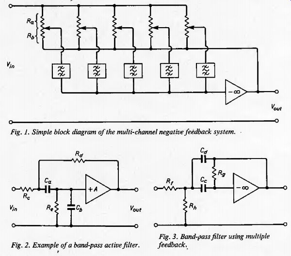
Fig. 1. Simple block diagram of the multi-channel negative feedback system.
Fig. 2. Example of a band-pass active filter.
Fig. 3. Band-pass filter using multiple feedback,
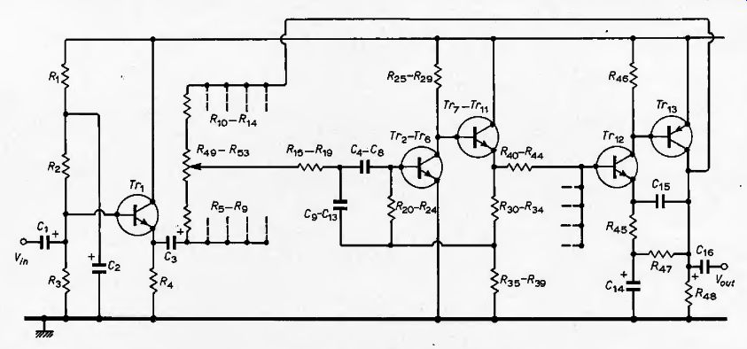
Fig. 4. Circuit of the five-channel tone control unit. Only one of the filters
and linear potentiometer is shown.
Fig. 5. Suggested power supply circuit using an integrated regulator.
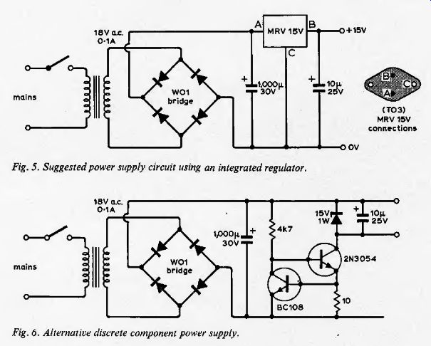
Fig. 6. Alternative discrete component power supply.
---
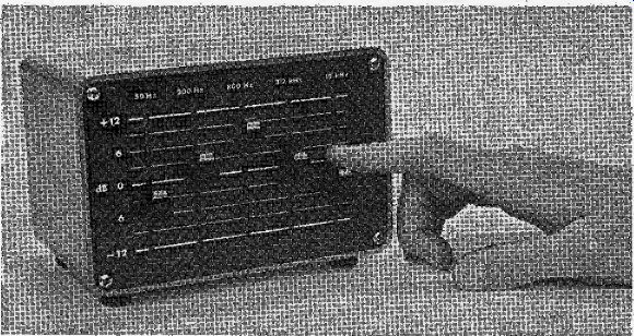
Five slider potentiometer controls on the front panel can he set to represent the required amplitude frequency response.
Active bandpass filter
In some systems there could be thirty or more channels, and since there is one filter circuit per channel, this must be designed as economically as possible within the limits of the specification. Assuming no inductors are to be used for the reasons mentioned before, the number of active devices should be minimized, unless component tolerances can be relaxed by using more. Close tolerance capacitors can prove especially expensive.
A simple circuit that meets these requirements is the Wien bridge derivative 4
Shown in Fig. 2, The response follows the tuned circuit law: VprntVin = -Ho)0(jod)l(i>0 2
-(jf+am0(jm)
where a = 1/g, w0 is the resonant frequency and the gain of the voltage amplifier is H = 1/3(6.5-a)
The component values are:
Cb = CJ1, Rc = 2/<»oCi R i = and Re = 2RC.
The most desirable feature of this circuit is that R and C values are independent of Q, and a>0 is independent of amplifier gain H. Unfortunately, the Q value becomes extremely sensitive to the value of for g ^ 1, and the margin of stability in such cases is narrow.
A circuit much more suited to this applications consists of an inverting op-amp with multiple feedback loops (Fig. 3). The response of this circuit is the same as before, but the component values are:
Rr \IH<J}QCC, H)(o0C, and Rs = 2Q/waCc.
If H = 2Q, Rh can be left out and F„u(/ Fin at resonance becomes:
KJVin = -2Q1 = Rf2Rf.
The minus sign in this expression indicates a phase reversal, so the main amplifier in Fig. 1 will now need an in-phase gain to obtain an overall negative feedback relationship.

Table 1; Table 2 --- Modified filter component values for narrower channel spacing. For worst case component tolerance, channel spacing error is 30%.
The above equations for this active filter circuit show that Q, passband gain and resonant frequency are determined solely by two identical capacitors and two resistors.
The demands on the op-amp are not great, and a single bipolar transistor suffices for low Q values. The transistors are used in the circuits to follow to provide a high stage gain in addition to filtering. This reduces the noise contribution of the main amplifier, and so long as the gain is greater than the number of channels used, the dominant noise contribution is that due to the first transistor stage of the active filter. This means a signal to noise ratio of about 70 db, which is better than most preamplifier inputs.
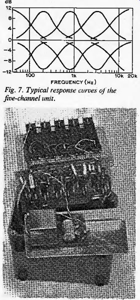
Fig. 7. Typical response curves of the five-channel unit. ------ Slider pots
mounted on the front panel are shown at the top with the main p.c. board (centre),
which carries the filter circuitry and input/output devices. The power supply
is on a separate board (bottom).
Practical circuit
The circuit is shown in Fig. 4. Only one filter is shown as the other four are identical, except for the values of Cx which are given in Table 1. An emitter follower Tr^ provides a low impedance input source for the bank of control potentiometers, The fixed resistors /f5.14 restrict the range of boost and cut to % 12dB. The active filter consists of a common emitter amplifier with a DC coupled emitter follower output. The Q value employed is unity and the passband gain at resonance should be approximately 28 dB. The filter outputs are fed to the main amplifier through ^40.4.4 which also provide the DC bias for this stage. Overall h.f, stability is obtained from the 6dB/octave roll-off provided by C13 and RAS. The unit complete with power supply fits into a 16 x IT x 11cm case without difficulty. A suitable power supply circuit using a monolithic regulator is given in Fig. 5. An alternative discrete component version, with a "ring of two" constant current generator feeding a zener diode in parallel with the load is given in Fig. 6. Either unit offers a ripple level which is inaudible with the unit in operation.
A small point worth noting is that calibration of the potentiometers in linear dB steps does not strictly follow the mathematical law, although only 10% error is produced over a 12dB range.
More channels
The performance of the five channel unit is encouraging enough to consider expanding the controls in range and number. As for range of control, about ±25dB is the most that would normally be required, even for special effects. One can obtain this range by reducing the values of if5_14 down to 2.7kfl.
To make sure that the overload margin is maintained under all conditions, it may be necessary to increase the standing current in Trl and Tr^ to provide sufficient drive voltage for the potentiometer bank. Transistors Tr1 and Tr^ may then have to be types of a higher dissipation rating. The number and spacing of controls will depend chiefly on application, thirty controls of one third octave spacing being a reasonable limit. The filter circuits can remain the same as the five channel unit; modified resistor values for two higher values of Q are given in Table 2, Using these modified circuits does not significantly alter the capacitor values for a given frequency, which are given by the equation
C(/iF) =1 (ffi0v/R7R9) ^ n.8//o(Hz)
Components
Values for the power supply components are shown in Fig. 5 or Fig. 6.
by J. R. Emmett, B.Sc.
----------
REFERENCES
1. Baxandall, P. J., ^'Negative Feedback Tone Control", Wireless World. Oct. 1952.
2. Ambler, R., "Tone-balance Control", Wireless World. March 1970.
3. Hutchinson, P. B., "Tone Control Circuit", Wireless World, Nov. 1970.
4. Sallen and Key, Transactions I.R.E., CT-2 No. 1, March 1970.
5. Huelsman, L. P., "Theory and Design of Active RC Circuits", McGraw-Hill, 1968.