Flexible design for use with Bailey 30 watt amplifier
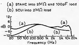
Fig. 1. Voltage/frequency curves of two well-known ceramic cartridges when
used with a conventionally-designed pre-amp with R itj=2MD, and a flat frequency
response.
[by B. J. C. Burrows, B.Sc.]
This article gives full circuit details of an economy and a high-performance preamplifier which use a new design principle to provide optimum performance from stereo and mono ceramic cartridges.
Many ceramic cartridges are capable of a very high standard of performance--but this is seldom realized in practice. This is because conventional pre-amplifiers cannot cope satisfactorily with the wide range of electrical parameters encountered in different makes of ceramic cartridge.
The two factors that cause the problems in pre-amplifiers for piezo-electric cartridges are: (i), self capacitance, and (ii), the degree of built-in mechanical equalization.
In conventionally designed circuits using high-value load resistances (1 -2 M-O). the pickup self-capacitance has a profound effect on low-frequency performance and hence on the rumble performance. Fig. 1 shows curves of output voltage against frequency for two well known pickups when operated into a conventional preamplifier with 2 M-o input impedance.
These show that the overall frequency response is far from flat.
Typical pickups vary in capacitance from 200pF to greater than 1500 pF, and with manufacturing tolerances plus the uncertain nature of the lead capacitance an overall variation of 180pF to > 2000pF is possible. To obtain good If. performance with 180pF needs a loading resistance of 18 M-o (not 1 M-o as commonly provided). If 18 M-ohm were used with a pickup of 2000 pF the bass turnover frequency would be 4.5Hz! This of course would result in very objectionable rumble and i-f arm resonance problems.
Conventional pre-amplifier designs do not allow for built-in mechanical equalization which varies from one pickup to another, and unfortunately the usual type of tone controls are not suitable for providing the necessary correction.
We can draw up a list of performance characteristics which an ideal pre-amplifier should possess:
(1) l.f. performance independent of cartridge capacitance;
(2) accurate rumble filtering independent of cartridge capacitance;
(3) means of correcting for variability in mechanical equalization (i.e. some form of 'tone balance' control).
(4) ability to cope with pickups of widely differing output voltages.
To these may be added; low noise/low distortion, good overload capability, built in tone controls, etc.
Economy pre amplifier
The complete circuit of the economy design is given in Fig. 2 for a positive h.t, rail system. A negative h.t. rail version is given in Appendix 1. For normal use connect A to A' and B to B' and use full circuit. For ultra-economy operation with any of the pickups except the Deram or CS91E, the second stage may be omitted by connecting A direct to B' and omitting the intervening circuitry associated with Tr2. Thus a very good, yet simple, gramophone amplifier may be built by using only 7>, and Tr3 directly connected into an amplifier with 100 mV sensitivity for full output.
Table of values for C1, C2 & R1 in economy circuit.

Fig. 3. First-stage design of equalization circuit.
Fig. 4 Operation of tone-balance control, Ra in Fig. 3.
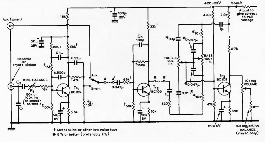
Fig. 5. Baxandall bass lift-and cut circuit.
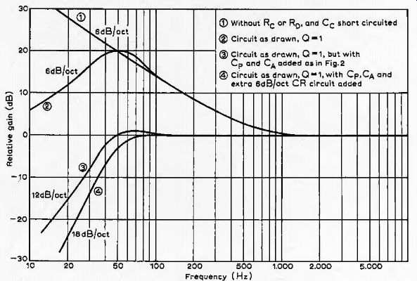
Fig. 6. Performance of circuit of Fig. 5 with fa=50Hz and f = 500Hz.
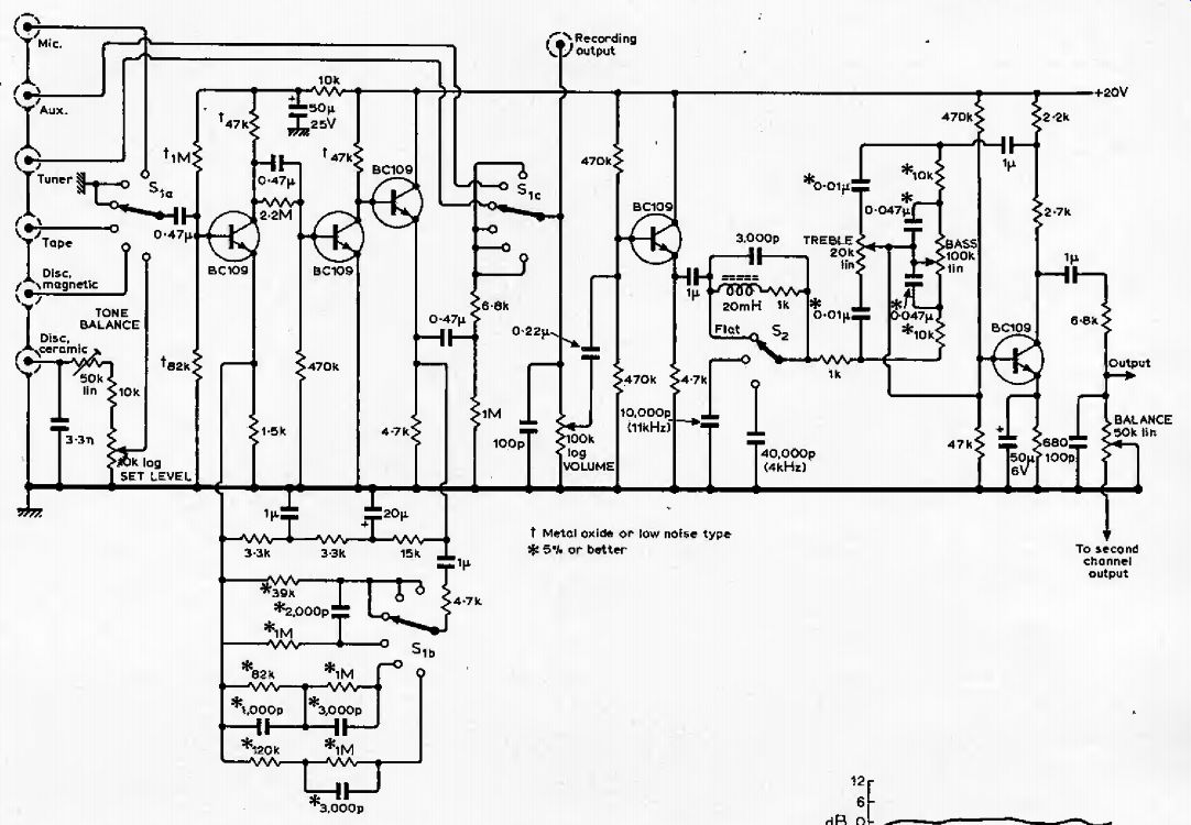
Fig. 7. Complete circuit of one channel of 'Bailey pre-amplifier’. No circuit changes are required for different ceramic pickup cartridges, only adjustment of Hone balance' and 'set level'.
Design principles of equalization stage
Last month the merits of the shunt feedback (or virtual earth) amplifier were mentioned as being very suitable for ceramic pickup equalization. Further, it was shown that loading the pickup with a low impedance had no effect on its internal e.m.i. In the present design, then, the effects of the variability in capacitance have been eliminated by swamping the pickup in every case with a shunting capacitor of 3.3nF or more. An input resistor of 75 k-o then gives an input time constant of 318us (equivalent to 500Hz); to match this, the feedback circuit has a time constant of 318's also (see Fig. 3); the complete circuit has a flat frequency response:
Vq RB CpACA T=r = constant= -p-& AM GJ3
If any one of the components suffixed A or B is made variable, a 'tone balance' type of control is achieved in a much simpler manner than circuits described previously', R is the best one to vary and provides performance variation as in Fig. 4. The value of Ra to give an overall flat frequency response is termed Rn. In practice only values of RA between Ra and R0/4 are needed to fully correct all ceramic pickups for their lack of complete mechanical equalization, e.g. the Sonotone 9TAHC pickup needs j?c/1.8 and the Connoisseur SCUI needs F^=F0/4, With an infinite gain amplifier in Fig. 3, overall gain is. flat down to DC theoretically. This is no use in audio work because of rumble and the If. arm resonance. Some form of rumble filtering is essential and may be built into the equalization stage by using the circuit due to P. J. Baxandalt. The essence of this circuit is in Fig, 5, and its performance in Fig. 6.
-----
Economy pre-amplifier specification
If a further high-pass RC filter is added, f o= 2rRc
... where a flat response to nearly 50 Hz is achieved with a rapid turnover to a slope of 18 dB/octave to attenuate ramble. Finally, with R A adjustable, the tone balance facility is still retained as with the basic circuit of Fig. 3. It is common to design rumble filters with cutoff frequencies much lower than 50Hz; but, to achieve adequate attenuation at 25Hz-a common frequency of the IF arm resonance-a high value off0 is required. The actual circuit of Fig. 2 achieves -28dB at 15Hz and -15dB at 25Hz. In practice this is very satisfactory.
The economy-design preamplifier closely matches the theoretical performance of Figs. 4 and 6 and provides excellent bass, good balance and excellent freedom from rumble. As shown in the table relating to the main circuit, the only circuit changes needed to accommodate different pickups are for curbing those with a very high output voltage with a capacitive divider. In connection with the table of values given for the input capacitors it is very important to stress that the values given must be used as specified and that the manufacturers' recommendations regarding load impedance and equalization must be totally ignored. This circuit has been specifically designed to take care of all the loading, matching and equalization factors and no further components are needed.
-------- High-performance pre-amplifier specification
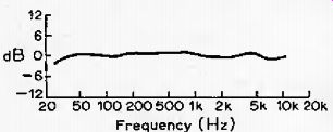
Fig. 8. Measured voltage/frequency curve for a 9TAHC operating into an 'economy
design' circuit with R^Rjl.8. The curve for the SCU1 would be just as flat,
but with RA=Rj4.
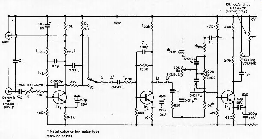
Fig 9. Economy circuit arranged for negative h.t. rail. For values o/C,,
C2, and Ru see table earlier.
The economy circuit as described fulfils all the design criteria enumerated earlier except for the slight inconvenience of changing two capacitors if pickups of widely differing output voltages are exchanged. The noise performance is very good with all the cartridges listed apart from two (the CS91E and Deram) with which it is satisfactory for everything but the most exacting requirements.
High performance pre-amplifier
This is based on the Bailey design of 1966 but with all the subsequent modifications to improve the filter and tone control 5 circuits, plus the addition of a complete ceramic-pickup equalizing circuit achieving the same performance with ceramic cartridges as the economy pre amplifier. The complete circuit is given in Fig. 7, which also incorporates one further modification to raise the cut-off frequency of the rumble filter in accordance with the design philosophy discussed in Appendix II. Equalization for magnetic pickups has been retained and is selected by the input selector switch.
The 'set level' control needs a mention. To avoid overloading the input stage, adjust the set level control with any particular cartridge to give comfortable listening level with the main volume control at about half of its maximum rotation. This control need be only a preset with screwdriver slot adjustable from the back of the preamplifier. The tone balance could be the same, or it could be brought out as a front panel control, or as a skeleton pot mounted internally or even a 'select-on-test' fixed resistor.
On paper, the specification of the high performance pre-amplifier looks most impressive, but subjectively the economy version is very good indeed, and both represent a considerable improvement on conventional designs in that reproducible low-frequency performance, effective rumble filtering independent of pickup capacitance, and a simple means of correcting for partial mechanical equalization have been incorporated. Fig. 8 in conjunction with Fig. I gives a comparison of the performance of the Sonotone 9TAHC and Connoisseur SCU1 using conventional loading (2Mf? plus flat amplifier), compared with the measured results on the author's 9TAHC using the economy circuit.
The calculated performance of the Connoisseur SCU1 with =RJ4 is a straight line coincident with the 0-db line on Fig. 8, although in practice there would be a variation of up to + 1dB about the 0-db line.
Modifications to provide a similar standard of performance with the Dinsdale Mark I and Mark II pre-amplifier circuits were incorporated in a previous article.
Appendix I
Alteration of economy circuit for negative h.t. rail operation, e.g. from a germanium transistor amplifier like the Dinsdale Mark I or 11, is basically to return all electrolytic capacitors to the positive potential rail, viz, the earth line (see Fig. 9). There are no modifications to circuit values apart from the voltage rating of the electrolytics.
Appendix II
Arm resonance (IF) is the tendency toward damped oscillation at a low frequency and is exhibited by most pickup arms. It has the effect of greatly increasing the cartridge output voltage at or near the resonant frequency. The frequency, fy, is normally in the range 10-25Hz, so its effect is to greatly increase rumble. The frequency of the oscillation is:
fir=I ^Hz
'TnfJW:
M is the mass of cartridge plus effective mass of arm measured at cartridge.
C is the compliance of stylus cantilever suspension. With M in grams, C is in cm/dyne.
With modern high compliance cartridges it is desirable to keep M very low-hence lightweight headshells-to make /yas high as possible. Generally speaking the lower the frequency of resonance the higher the Q, and vice versa. But a higher resonant frequency is more trouble electrically. A low-frequency high-{2 resonance causes mechanical difficulties-the pickup tends to leave the record surface when excited, A resonance at 25Hz is acceptable mechanically if the Q is low enough and its electrical effects can be removed with a steep slope filter. Below this resonant frequency the cartridge output voltage falls off very sharply indeed (24dB/cictave) thus providing the required severe attenuation of sub-audio frequencies.
With regard to pre-amplifier design, the point to note is that the highest amplitude rumble components will be at, or near, the IF arm resonance. A filter in the preamplifier should ideally provide 12dB or more of attenuation at 25Hz, yet not interfere with IF audio response. A cut off frequency of 50Hz with slope approaching 18dB/octave is a very good compromise since it causes very little error in the R.I.A. A. equalization, yet gives -15dB at 25Hz and 25dB at 15Hz.
References
1. Ambler R„ Tone Balance Control', (W. World. March 1970. pp. 124-6, Hutchinson P.B., 'Tone Control Circuit!, Wireless World, November 1970. pp. 538-40.
2. Baxandall PJ., 'Gramophone and Microphone Pre-amplifier', Wireless World January 1955. pp. 8-14.
3. Bailey A.R,, 'High Performance Transistor Amplifier', Wireless World, December 1966. pp. 598-602.
4. Bailey A.R. 'Modified Treble Filter for Bailey Pre-amplifier', Wireless World, June 1969. p. 275.
5. Quilter P.M,, Letter to the editor, Wireless World, April 1970. pp. 172/3.
6. Burrows B.J.C., 'Ceramic Pickups and Transistor Pre-amplifiers', Wireless World, February 1970. pp. 56-60.