Improvements for greater flexibility in tailoring audio signals
by M. V. Thomas, B.A.
The main disadvantage of the Baxandall tone control circuit is that if boost and cut are required at a particular frequency a much greater effect occurs at the extremes of the audio range. Modifications are described to limit the degree of this effect.
The Baxandall configuration has for some time been the almost universal choice of audio amplifier manufacturers for their tone control circuits. This is due in no small measure to its simplicity of construction and ease of use, and it is difficult to envisage any improvement of the circuit whilst retaining only two controls. However, once a decision to increase the number of controls is made, the field becomes wide open, the most obvious development being to have each control affecting the level of a limited band of frequencies. Such circuits are obviously much more elaborate than the basic Baxandall type, and require careful design to prevent excessive interaction between the controls. This article describes a modification to the basic Baxandall circuit which greatly increases its versatility whilst maintaining its simplicity.
The main disadvantage of the basic circuit is that it has its greatest effect at the extremes of the audio range, as shown in Fig. 1, For example, if a 6dB boost is required at 4kH2, one must simultaneously, tolerate a much greater boost of perhaps 18dB at 16kHz. Furthermore, the turnover frequency of the bass control depends on its setting, but this does not apply to the treble control! This effect is also shown in Fig. 1, and the reason can be seen in Fig, 2, which shows the basic circuit. At very low frequencies the impedances of the capacitors are high and the circuit is essentially resistive. The bass control then acts as a simple gain control and the treble control has no effect. As the frequency is increased, the bass control is progressively decoupled by C, and C2 , the relevant time constants being C^.^ and But the relative values of R2 and R3 obviously depend on the setting of the control, this causing the variation in turnover frequency as shown in Fig. I. For example, to increase the bass boost, Ji^ must be increased, thereby increasing the C2R2 time constant and increasing the turnover frequency. At higher frequencies (above IkFlz) the bass control is completely decoupled by C; and C2, and the impedance of C, has fallen to a value where the treble control begins to have a significant effect (capacitor is often replaced by two capacitors, one at each end of the track of the treble control, but the effect is basically the same). Resistor Rs prevents the bass control from loading the treble control, and the time constant which primarily decides the treble turnover frequency is C2R5, which is independent from the control settings. At very high frequencies (above 10kHz) the treble control acts as a gain control. Resistors R,,R4, R6 and R9 serve to limit the. effect of the controls at their extreme settings, and are comparatively small in value, so they do not affect the basic operation of the circuit.
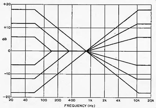
Fig. 1. Idealized responses of the Baxandall type tone control circuit.
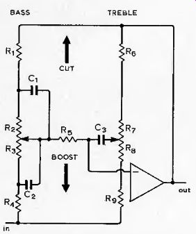
Fig. 2. Baxandall-type tone control network.
Fig. 3. Synthesis of "shelf" responses using completely separate
boost and cut networks. In the example shown, the maximum overall boost is
+ 12dB (curve C), but at 20kHz this overall boost is obtained by applying
40dB boost and 28dB cut (curves A and B), thereby causing overload or noise
problems, depending: on which operation is performed first.

Fig. 4. As Fig. 2, but with the addition of the two effect controls.
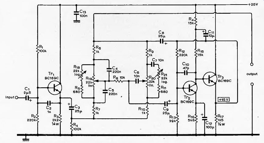
Fig. 5. Complete circuit. Resistors can be | watt unless shown otherwise.
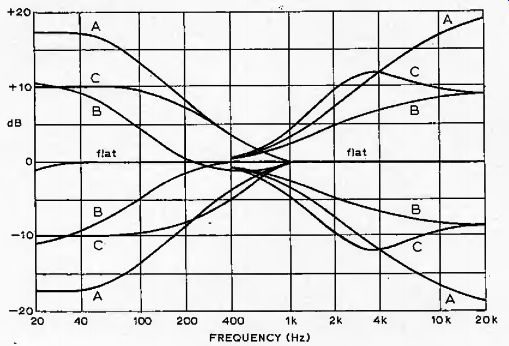
Fig. 6. Selection of the frequency responses obtainable with the circuit.
See text for further details.
Whether this difference in mode of action of the bass and treble controls, is advantageous is a difficult question, and one could no doubt argue either way.
However, it is about all one can do with a simple RC network, unless completely separate boost and cut controls are used. Using this approach it is possible to synthesize "step" responses as shown in Fig, 3, but in order to obtain a flat response it is necessary to simultaneously boost and cut the signal, which can. cause overload and noise problems as the two operations are performed in different parts of the circuit, in contrast to the Baxandall arrangement.
Possible modifications of the circuit to limit its effect at the extremes of the audio range were therefore considered.
It was decided that the most useful addition would be of separate "effect" controls for bass and treble, which would limit (in a symmetrical fashion) the maximum degree of boost and cut obtainable from the bass and treble controls, and further reference to Fig. 1 shows how this may be done. The maximum boost and cut of the bass control are decided by R, and respectively, so the desired result could be obtained by replacing these with variable resistors, but this arrangement has two disadvantages. Firstly, two controls are required, and secondly, changing the values of these resistors will cause some change in the turnover frequency of the bass control. However, the same result can be achieved with neither of these disadvantages, by connecting a single variable resistor directly across the bass control, as shown in Fig. 4. This control simply acts as a potential divider in conjunction with Rj and R4. As the resistance of the control is reduced, the fraction of the input and feedback signals appearing across the bass control is also reduced, thereby limiting its. maximum effect. A similar modification to the treble control will not have the desired result, because of the fixed turnover frequency of this control; it would indeed reduce the maximum boost and cut of the control, but one could obtain exactly the same frequency response by removing the "effect" control and by having the treble control at a less extreme setting! This state of affairs can be prevented by including a series capacitor, as shown in Fig. 4, so that the "effect" control is operative only above a turnover frequency decided by the values of this capacitor, R6 and Rp.
The complete circuit incorporating these modifications is shown in Fig. 5, and apart from the additions it is quite conventional.
The only extra precaution necessary is to ensure that it has a reasonably high drive current capability, as the impedance of the control network can be comparatively low at some control settings.
However, the worst-case maximum output of the circuit is approximately four volts RMS before clipping, which should be perfectly adequate. The transistors used in the prototypes were BC169Cs; these have a Vca of 30V, which allows the use of a fairly high supply voltage for the circuit. Transistor Tr, provides a low impedance drive to the network while 7>y and 7>j form a bootstrapped amplifier.
The low distortion and low .output impedance of this configuration make it an ideal choice for this application. The circuit has a gain of unity with the controls set flat, and C, and C10 reduce the RF gain to prevent instability. Resistors ^^2 and provide DC feedback to hold the emitter of Trs at 15V, this being a useful point to check when testing the circuit. Logarithmic pots are recommended for the two effect controls. The "top" end of each track should be left unconnected so that the controls will then have their smallest modifying effect when fully clockwise.
Resistors R, and R,/ in Fig. 5 prevent the effect controls from completely swamping the bass and treble controls when the former are fully anticlockwise; the values shown set the limits at the audio extremes to ± 4dB.
Fig. 6 shows a selection of the frequency response curves which can he obtained from the circuit. The set of curves marked "A" obtained with the effect controls fully clockwise shows the responses with the bass and treble controls at their extreme settings, and set "B" is similar except that this shows the responses with the bass and treble controls at approximately half maximum settings. These curves are almost identical to those obtainable from a conventional circuit-compare for example with those of the tone control circuit in ref. 3. The only difference is that the bass and treble responses have been deliberately arranged to overlap rather more than usual, so as to take fuller advantage of the effect controls. Set "C" is obtained with the bass and treble controls at their extreme settings but with the effect controls set to limit the responses at the audio extremes to the same as those of set "B", and this clearly shows the advantages of the extra controls.
Basically, by the use of these controls it is possible to alter the level of a band of frequencies far more uniformly than with a conventional circuit, and this advantage is very noticeable in use, being considered well worth the extra complexity.
References:
1. Hutchinson, P, B,, "Tone control circuit", Wireless World, Nov. 1970, pp.538-540,
2. Quilter, P. M,, "Low distortion tone control circuit". Wireless World, April 1971, pp. 199200.
3. Walker, H. P., "Stereo mixer". Wireless World, June 1971, Part 2, pp.295-300.