Using a single bass speaker in a stereo system
by D. C. Read, B.Sc.
The author finds that active crossover networks, giving better speaker damping and improved transient response, sound better than passive ones as well as being easier to adjust. But the system first designed (December 1973) needed six amplifiers. This article therefore describes three ways to reduce size and cost, by using a common bass unit with 1-cu.ft sealed enclosures, by using the bass unit with 0.33-cu.ft enclosures, and by omitting the bass unit.
Alterations to active filter circuit values for these options are given together with a modification to the "full" six-unit system.
The first and most obvious economy in the previous active crossover design was to follow the well-tried example of Baxandall* using . the fact that low-frequency sounds are non-directional and have a mixed mono and stereo system.
Fortunately, fpr modern living rooms of average size, this non-directional effect extends well into the audio band. By combining a single bass speaker with a pair of relatively small mid-range/tweeter boxes working in stereo there is an immediate saving of one power amplifier, its driving filter circuit and one large enclosure.
Although one filter and amplifier assembly would be unchanged, the other would be smaller, with about one-third of the components removed from the filter (front board in photograph) and two power amplifier boards instead of three.
An added practical advantage is that the bass speaker can be placed in any convenient position to suit the general room layout.
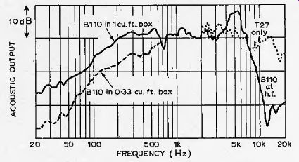
Fig, 1. For the common -bass system the mid and upper-ranges use B1J0 and
727 drive units, as in the original design. Graph shows axial response of
BJ10 in a 1-cu.ft sealed box (upper solid line). T27 curve (broken line)
shows an upper crossover of about 4kHz is suitable.
Lower B110 curve shows axial response for a small, 0.33-cu.ft sealed box, for which slope correction is needed (see Fig. 5). Acoustic response curves taken with a writing speed of 80 mm/s and a paper speed of 3 mm/s.
Choice of bass crossover
Having decided on a combined bass arrangement, the first requirement was to determine where in the audio band to make the change between mono and stereo operation. In doing this work, the ease of adjustment afforded by active filters was most helpful.
The single bass unit, KEF type B139, was installed in a box of about Scu.ft and then subjected to listening tests in a normal-size living room. For experimental purposes, the middle and upper frequency sounds were produced by units in the transmission-line enclosures described in the previous article. Simple A-B switching allowed repeated comparison between this combined bass set-up and the complete 2 X 3-way system, i.e. between mixed mono and stereo, and full audio-band stereo.
Initially, the bass speaker was fed with combined signals from the two channels up to about 490Hz: this was the bass crossover frequency already in use for the transmission-line speakers.
But stereo separation was not then maintained over the whole band: the single source of low frequencies could be identified and located when moved. The crossover point was then lowered by successive amounts until, with it set at 150Hz, the mono bass effect disappeared. Thus, when compared against the full 2 X 3-way stereo it was found that the IF speaker could be placed virtually anywhere in the room, facing in any direction, without noticeable change in the stereo image.
The 150-Hz crossover frequency determined as above provided for satisfactory (i.e. undetectable) mono bass for a stereo installation working in a room measuring about 15 feet square. In a listening room with dimensions considerably greater than this, however, the presence and location of the single source of IF may become apparent, and it will then be necessary to lower the stereo-to-mono changeover point.
To move the changeover point either way, the response curves of both the midrange band-pass filter (high-pass) and the bass-unit low-pass filter must be modified by altering the roll-off frequencies of the 6dB and 12dB/octave circuits (the circuits surrounding IC3/Tr5 and IC4/Tr6 in Fig. 2). As the change of frequency in each instance is likely to be relatively small, the appropriate new component values can be deduced by simple linear scaling. For readers who wish to re-calculate circuit constants, perhaps to satisfy the requirements of different units or considerably changed listening conditions, the procedure is. given in a section at the end of this article.
The component-scaling process is straightforward. In all instances, suppose the existing crossover frequency is /j and the wanted frequency is f2. Suppose also, for example, that the required frequency shift is that necessary to lower the crossover point (to raise it each multiplying factor would, of course, he inverted). In the feedback circuit to input 3 of IC3 (Fig. 2), either the two C values (33nF) or the R values (2 X 56kO and 36k omust be increased in the ratio f lf~. For the Trs input circuit increase either the series C {tof,//, x 0.033pF) or the two shunt ./?s (both to/,^ X 62kO). Similarly, in the IC4 circuit, new values are found for. the input 3 components such that either the 100 kQ and 15kQ resistors or the 33 and 6SnF capacitors are increased by the factor of /•.//. The Tr6 input circuit is modified in the same way. as for Tr5.
As a further practical point relating to the use of a single, combined bass system as suggested here, note that the power amplifier described in the first article (Fig. 4 of the December article) is easily able to provide the necessary drive for a single unit taking IF signals from both channels, or even from four channels.
Smaller mid and upper range stereo units With the optimum changeover point between stereo and mono working now established, it was necessary to construct a pair of small enclosures with speakers to produce the mid and upper audio frequencies. Identical units to those already used (KEF types B110 and T27) were used.
An obvious minimum requirement here was that the bass response of the midrange unit must extend at least to 150Hz.
Past experience suggested that for this an enclosure volume of about 1 cu.ft would be suitable. Accordingly, a sealed box of this size was made, with dimensions 10 X 20 X 9in. Damping was provided by a thick coat of car under seal on all internal surfaces and the box was filled with about ylb of long-fiber woo): an inside layer of 2-in. foam plastics material would be a suitable alternative.
With the units installed, the assembly was tested in non-reverberant surroundings. As the B110 axial response given in Fig, 1 shows, the arbitrary estimation of enclosure volume was about right and obviates the need for slope equalization in the. mid-range band-pass filters. The T27 response curve, drawn dotted in Fig. T, shows that an upper crossover frequency of 3.5 to 4kHz was suitable here; the Overall 6dB/octave slope is easily offset by making the high-pass filter IF roll-off more gradual.
Fig. 3 illustrates the three active filter responses as finally set for the mixed system. These curves are the voltage outputs from the full circuit given in Fig. 2, with R2 = 33kQ, R3 shorted and R5, R6, C, omitted. Note that two each of the band-pass and high-pass filters shown in Fig. 2 are needed but only one low-pass circuit
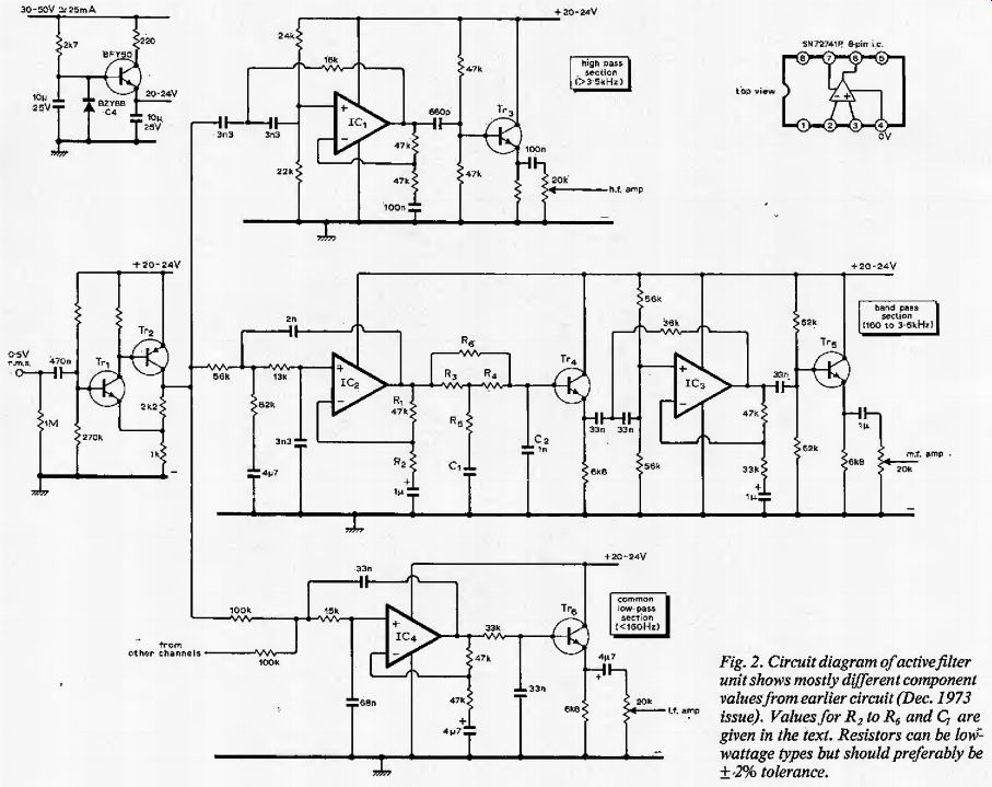
Fig. 2. Circuit diagram of active filter unit shows mostly different
component values from earlier circuit (Dec. 1973 issue). Values for R2 to
R6 and C, are given in the text. Resistors can be low-wattage types but should
preferably be ± 2% tolerance.
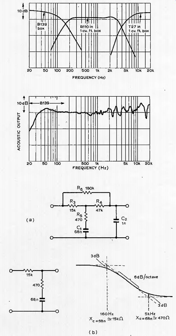
Fig. 3. Active filter responses for common bass system. Curves are voltage
outputs from Fig. 2 circuit, with R , R , shorted and Rs, R6, C, omitted.

Fig. 4. Axial acoustic output for B139 unit in separate If. enclosure and
1-cu.ft box using B110 and T27, in non-reverberant surroundings.

Fig. 5. Correction circuit used in bandpass filter to compensate for response
of0.33-cu.fl box in Fig. 1. Other components in (a) give part of the 18dB/octave
roll-off at the top of the passband (C2, R4) and R6 determines in-band slope
(see text for value of R2).
Overall response with combined bass
To check the overall acoustic output of the total system, the bass speaker together with a 1-cu.ft mid-range/tweeter assembly was tested in non-reverberant surrounding.
Fig. 4 shows the complete response.
Note that only one of the stereo pair was used to obtain the curve of Fig.. 4 because large differences in phase response between individual units of the same type (e.g. as exhibited by different examples of the BIIO unit) resulted in a spikey response with almost complete cancellation at some points. Such disparity in phase performance is,, of course, a well-known failing of cone radiators; plane-driven electrostatic speakers are much more consistent in this respect. However, in normal, domestic surroundings, multiple reflection tends to smooth out such variations in combined response and therefore largely overcomes the problem.
Active-filter phase response
While on the subject of phase performance, it should be mentioned that this was an aspect of active-filter operation which was carefully considered at an early stage. For the full stereo installation outlined in the December article, the various filter phase responses were calculated and their combined effect on acoustic performance tested. Specifically, this was compared to performance with the conventional passive-network equivalent. Detailed results of these tests have not been given because they showed only that even the largest differences in phase characteristic, particularly those occurring in the crossover regions, had little effect on sound output. The one observable change was a frequency redistribution, without increase in amplitude, of troughs and peaks in the overall response.
Even smaller stereo speakers
Although the combined-bass speaker enclosure used in the mixed system can be of any suitable shape and put in any convenient out-of (he way corner, the mid and upper-range assemblies must of necessity occupy particular positions, divided and directed so as to obtain the intended stereo effect. But, in rooms where space is at an absolute premium, even the Tcu.fl enclosures used as above may be too large. To meet this objection and to exploit other properties of active filter, notably their possible use in correcting speaker response deficiencies, a pair of 0.33-cu.fl boxes was built (dimensions 8 X 6 X 12in) to form part of a modified stereo/mono system using the same units as before, i.e. one B139 and two each B110, T27.
Mid-range unit slope correction The. IF axial response of a B110 in a 0.33-cu.ft enclosure is given by the lower, dashed, curve up to 1kHz in Fig. 1.This shows that slope correction is needed in the band-pass filters which provide input signals for the mid-range units. An R-C network feeding Tr4 can be used for such equalization. In Fig. 5a, the correction network is re-drawn with appropriate values. Here, R3, and C, give a 6dB/ octave bass lift over the required frequency range as shown in Fig. 5b.
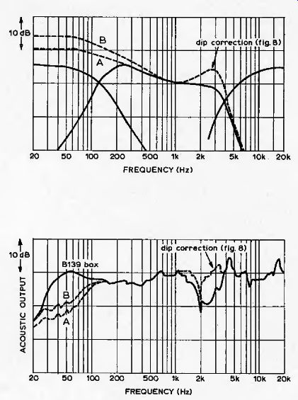
Fig. 6. Filler response for small enclosure, using values of Fig. 5 (a).
Curves A and B are obtained with high-pass part of bandpass filter removed
(by taking output from Tr4 emitter) and apply for an inexpensive system using
only the 0.33-cu.ft enclosures (see Fig. 7).

Fig. 7. Axial acoustic response for B139 unit in separate enclosure and
0.33-cu.ft box, in non-reverberant surroundings, showing dip at 2kHz before
and after correction. Curve A applies when common bass unit is not used,
and high-pass filter of bandpass section is removed (to the right of Tr4).
Improvement at B is obtained by making C, WO nF and R6 270k-o.
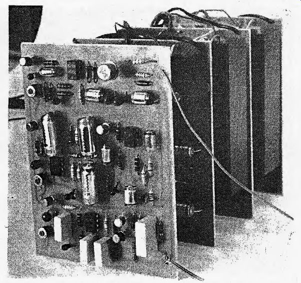
------- Complete amplifier for one channel. Front board is modified active filter, including IF
section and voltage regulator, not needed for the other channel. Note reduced-size heat dissipator for h.f power amplifier.
Components R4 and C2 provide a similar slope as part of the overall 18dB/ octave roll-off at the top end of the pass band. The value of R6 determines the amount of in-band slope obtained for the whole circuit.
Using the values shown in Fig. 5a, the band-pass filter output response is as shown full line in Fig. 6. The other two filter responses remain as before but are included here to show how they relate to the modified band-pass curve.
Mid-range dip correction
Fig. 7 gives the axial response in non-reverberant surroundings of the smaller mixed system, i.e. of the single B139 bass unit together with the B110/T27 combination in a 0.33-cu.ft enclosure. It shows that the bass response has been considerably improved, but there remains a large dip around 2kHz. Fortunately, since the response region requiring correction occupies a narrow range of frequencies mainly below the h.f, crossover point, the dip can largely be filled by creating a suitable peak in advance of the upper band-pass filter roll-off. This is done by adjustment of feedback over the first of the 74 IP amplifiers (/C, in the low-pass section of the band-pass filter). Fig. 8, which shows the roll-off characteristic for a 741P gain setting of 2.74, achieved with Rj = 47k-ohm and 7?;, =27k-ohm (gain= 1+7?j/ R ,). (Peak height can be changed by altering gain slightly.) With this modification to the band-pass filter circuit the overall response appears double-humped as illustrated in Fig. 6 by taking the upper dotted curve. The resulting acoustic response of the system is then as shown in Fig. 7 with the broken dip-corrected curve replacing the full-line one between 1.2kHz and 3.8kHz.
Miniature full stereo arrangement
A simpler stereo system was set up by using only the B1I0 and T27 units in the 0.33-cu.ft boxes, i.e. without the large combined bass enclosure. This economy also dispenses with about half of the filter circuitry; the parts now required are just the low-pass sections of the original band-pass filters and the two unmodified high-pass sections for the T27 tweeters.
Further equalization must be added to give the B110 units extra IF response and thereby compensate for the absence of the B139 speaker.
In Fig. 6, the dotted line from 230Hz to 20Hz (curve A) shows the output from Tr4 in Fig. 2. Because the lC3lTrs circuit is not included in this reduced-scale system, it is therefore the low-pass response applicable to signals feeding the B110 units. The high-pass filters and output characteristics remain as before. The axial response of one B110/T27 assembly (0.33-cu.ft box) as used for this full stereo arrangement is given in Fig. 7 by taking the full-line curve plus dip correction above 200Hz and adding to it broken curve A below this frequency.
Evidently, bass is still lacking below 100Hz, Curve B gives a possible 4dB maximum improvement here, and corresponds with the curve B filter response illustrated in Fig. 6. For such additional IF output, Cj in the correction network (Fig. 2 or Fig. 5a) becomes 0.1 pF and R6 is increased to 390kQ. More bass boost than is shown by curve B in Fig, 7 could be obtained by other changes to the R-C network values, but, whenever extra IF response is sought from the B1I0 in this way, there is a danger that excursion of the cone driving coil might become too great; limiting and consequent distortion is then inevitable.
For this reason such increased bass output must be accompanied by a restriction in overall listening level, especially for music with a heavy bass component.
Note that both the A and B filter curves give steady IF increase down to about 80Hz after which the response gradually levels off and the B110 characteristic takes over. This is a deliberate compromise. It not only helps to overcome the problem of excessive cone movement but also gives some protection against spurious low-frequency signals such as those caused by rumble.
Use of combined bass for quadraphony
A mono-bass arrangement using active filter circuits to the design described in this and the earlier article has been applied to a quadraphonic installation. When considering the extension of a split-band, multiple-speaker stereo system to quadraphony, the prospect of doubling-up yet again on most of the equipment is a daunting one, and any possible saving in outlay-especially if this can be done without reduction in performance-is an attractive proposition. The use of a single bass speaker offers just such an economy.
Obviously, twice the (stereo) complement of filters and amplifiers serving the mid and upper frequency ranges must be provided. For this quadraphonic application, however, the only change necessary in the basic circuit of Fig. 2 is that four mixing resistors, each of 200kQ, are now needed to combine the IF signals at the input to IC4. Although this input point is not a virtual earth, there is no danger of crosstalk between the four contributing channels because their outputs are fed from constant voltage sources as represented in Fig. 2 by the circuit containing Tr1 and Tr2.
Low output-impedance amplifiers in this position were, of course, already a necessity to prevent interaction between the stereo channels and, equally important, between the filters.
Although the foregoing outline suggests that bass combination is as easy to achieve for quadraphony as for stereo, there is a difficulty which may arise concerning the matrix system used and its effect on channel combination at low frequencies. In particular, the SQ coding system, and more especially the better QS system, which makes use of phase as well as amplitude relationships to improve separation, could create interaction problems at frequencies where the channels are combined. If this happened, it would be difficult to predict the subjective result; it would certainly depend on the program content.
In mono reproduction of SQ and QS records, sounds intended for the center back are heavily attenuated, and with QS records, left back and right back sounds would be 7.7dB down on the front sounds-Ed.
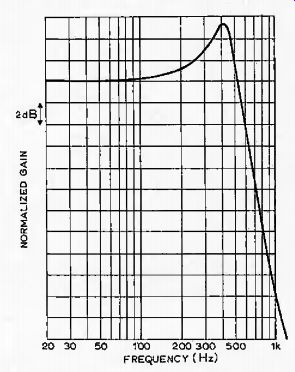
Fig. 8. Peak of appropriate height to compensate dip in Fig. 7 obtains for
R2.~27kQ, with R, -47kCl in IC 2 circuit.
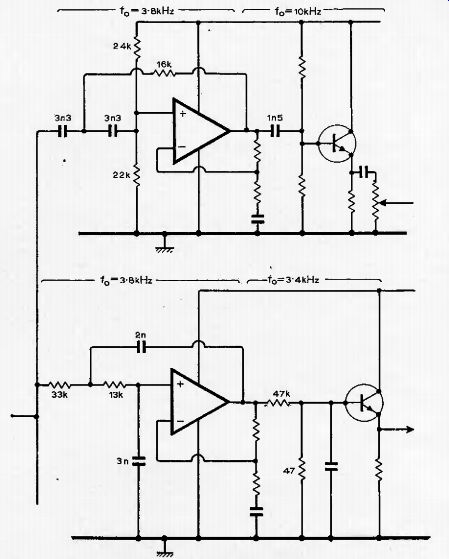
Fig. 9. Original active crossover design (December) can be improved by lowering
upper crossover frequency to 4kHz. New component values shown above.
Modification to original system
Readers who have either built or considered building the full 2 X 3-way system may be interested in a modification to the filter circuit given in Fig. 2 of the December 1973 article.
The change concerns the upper crossover frequency which has been lowered to 4kHz, In the original design, a 6kHz crossover was chosen so that a direct comparison of performance could be made with the Radford FN10 passive network.
But as mentioned in passing (p,576 of that issue), the subjective effect was improved by shifting the crossover down by 2kHz; the reason for this improvement was not obvious at the time. Howevet, subsequent discussion with the maker of the KEF B110 unit revealed that, coupling between coil and cone becomes increasingly less stable at frequencies above about 3 kHz (hence the response peak at 5kHz as shown in Fig.. 1 of this article). By reducing the mid-range response in this region and making more use of the available lower-end output from the T27 tweeter, adverse effects from the B110 are avoided.
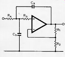
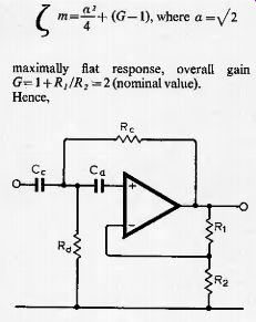
Fig. 10 shows the relevant parts of the circuit, taken from Fig. 3 of the December 1973 article, showing amended values.
Component layout. Photocopies of printed board positive transparencies, together with component layouts and a response curve for the modified crossover, are available from the Wireless World editorial office.
Please send a stamped and addressed envelope for these.
Appendix
Circuit below applies to a low-pass filter where Ca, C,. and Ra, Rb are the component values to be determined.
First, choose a suitable value for Ctt (in pF) and thus find a value for a number, A;, where k --¦ l'i Cj'. . In this expression, /„ is the 3dB-dowri frequency which can be related to a wanted crossover frequency (normally at the 6dB-down point) by inspection of the appropriate curve.
Next, calculate (= -+ (G1). where a =y/2 maximally fiat response, overall gain Gl+RJRi = 2 (nominal value). Hence,
Having thus established the basic curve shapes, further adjustments will have to be made to achieve the optimum performance. For example. Fig. 1 shows that the T27 tweeter output tends to fall at the higher frequencies and this tendency is counteracted by moving f0 for the 6dB/ octave section of the high-pass filler to about iOkHz. This 'softens' the roll-off shape and also gives the Wanted rising characteristic.
A similar technique was used to compensate for unit deficiencies at the IF
end of the band. Other forms of response adjustment, , such as roll-off "corner sharpening" and in-band dip correction are achieved as already described by altering the appropriate op-amp gains.
The above points are mentioned as a guide to the various ways in which active niters can be tailored to fit particular requirements. But, obviously, there are as many combinations and permutations of adjustment method as there are conditions to satisfy; it is largely a matter of trial and error which form is chosen to obtain the best result.
Letters to the Editor
ACTIVE CROSSOVER NETWORKS
As a designer of p.a. systems using active crossover networks, I was very interested to read the article by D, C. Read in your November, 1974, issue. However, I feel that readers may be confused by the graphs for the BUO unit in Fig. 1, and in particular by the conclusions drawn from them.
The graphs are obviously drawn for the free field responses, and predominantly show the effect not of internal cabinet volume, but of external cabinet dimensions. In fact the sound power output response for this unit is improved by the smaller cabinet, the 0.33cu. ft enclosure being near the optimum for the B110, the enclosure Q being just under 1 at around 75Hz, giving a response flat down to around 80Hz and dropping at 12dB/ octave below this. Response curves for small speakers such as this should always he taken under the same conditions as their normal use, in this case almost certainly up against a wall, corresponding roughly to half-space conditions. Under these conditions the BUO will show a flat response up to around 600Hz, rising after this up to about 2kHz, where it levels out again. This unit should hot be used on bass signals in as large a cabinet as leu.ft, as there will be almost no stiffness control over the low-frequency cone excursions.
A worthwhile improvement with these small enclosures is to provide, electronically, deliberate cross-talk between stereo channels below about 150Hz, thus cutting down considerably on cone excursions with bass signals predominantly in one channel or the other, unfortunately quite common with modem recording techniques.
To the best of my knowledge, the first company to do this cotnmerciaily was Servo-Sound.
K. C. Gale, Poole, Dorset.