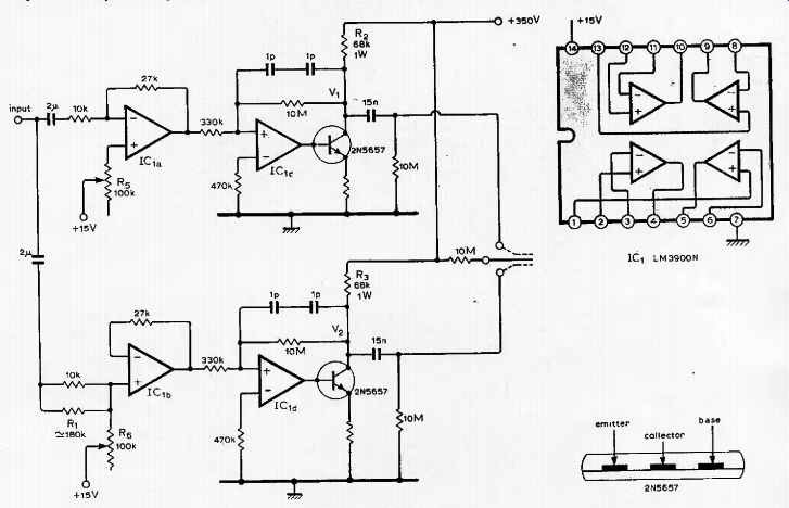
This circuit has been used successfully with a pair of headphones based on the W.W. design Dec. 1968. The amplifier can be driven from the headphone output of most power amplifiers. Potentiometers R1 and are used to set V1 and V2 at half the supply voltage.
Resistor R1 is required to compensate for the small signal resistance of a diode in the non-inverting input of IC_1b. If headphones of greater capacitance than 150pF are used it is necessary to reduce R2 and R3 to maintain the power bandwidth. It may then be necessary to heat sink the power transistors. The + 15V bias supply for lC_1a and IC_1b must be well filtered. The amplifier has a small signal frequency response of (-3dB) 10Hz to 40kHz, a power bandwidth of 10Hz to 15kHz, and a total harmonic distortion at 1kHz (almost entirely second harmonic) of 0.1% at 50V pk-pk and 1.0% at 300V pk-pk output.
N. Pollock, Sandringham, Australia.
---------