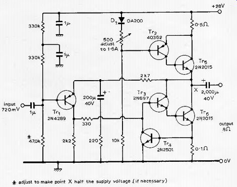
This circuit was designed using easily available components. Its operating conditions are unconditionally stabie, unaffected by individual transistor parameters and the transistor types are not critical. Short-circuit protection is provided by the constant-current source D1, Tr_2, Tr5 and Tr4. Transistor Tr4 may be omitted if short-circuit protection is not required. The amplifier may be altered for a different ioadimpedance (R) or power output (W) by putting the output-stage current 1 ~ 2W/R, and supply voltage equal to 2 + 0.61 + 2 √ (2WR). Dissipation in the output transistors is roughly W X 4 watts, so the heat sinks need to be adequate. The amplifier shown will deliver 10W into an eightohm load. Diode D1 and Tr-2 should be in thermal contact, A. H. Calvert, London NW1.
-----