An article summarizing the development of design theories and concluded with two systems for construction
by J. Dinsdale, M.A., M.Sc., Cranfield Unit for Precision Engineering
After a period in the infancy of the gramophone when it was universally employed, the horn loudspeaker has fallen from popularity, due probably to its relatively large size, complexity of manufacture and hence high cost. Although full-range horn systems are used today only by a small number of enthusiasts, most experts are unanimous in acclaiming their virtues as loudspeaker enclosures, especially their high degree of realism and "presence". These articles examine briefly the history of the exponential horn loudspeaker and discuss the theory of horn-loading and the technical requirements of a good design. Comprehensive data are included for a wide range of horns, together with outline designs for a large and a small horn, suitable for domestic use, The idea! exponential horn consists of a straight circular tube whose cross-sectional area increases logarithmically along its length from a small throat (at which is mounted the loudspeaker) to a large mouth.
Extreme bass notes demand a mouth of very large area (20 to 30 sq. ft) and a horn at least 20ft in length, whereas extreme treble notes require a horn with dimensions of only a few inches. For this reason most wide-range horn systems will incorporate a number of separate loudspeakers, each with its individual horn of appropriate length and mouth area. To accommodate these horn combinations within a cabinet of reasonable size, the bass and middle horns are generally of square cross-section and are "folded" into a complicated pattern. Unfortunately, the inevitable restrictions and compromises introduced by these departures from a straight axis and circular section can cause serious variations in the frequency response, and much of the art of horn design is concerned with achieving a product of reasonable overall size and cost, without sacrificing any of the astonishing realism which is obtainable from the ideal horn.
The efficiency of a horn system will be typically between 30 and 50%, a figure to be compared with 2 or 3% for a bass-reflex enclosure and less than 1% for a totallyenclosed box.
The principal reasons for the evident lack of popularity of the horn probably lie in its dimensions and cost. The overall size of a bass horn, even when folded into a cabinet of reasonable shape, wiil be larger than a bass-reflex or infinite baffle enclosure of comparable specification. But although one reads occasionally of straight horns up to 20ft long, excellent results may be obtained from horns of more moderate dimensions; for example a complete horn system may be folded into an attractive cabinet of volume only 6 cu. ft, a not unreasonable size for domestic listening. The cost of horn enclosures is often considered to be prohibitive, and it is true that there is considerably more work in constructing a folded horn than in other enclosures; furthermore, this is work best performed by craftsmen and not easily adapted to "production-line" methods. Nevertheless, the building of a folded horn is by no means outside the capability of a competent do-it-yourself enthusiast, and it is to these individuals that the practical designs will be directed.
Although the early acoustical gramophones or phonographs employed horns of one type or another to couple the diaphragm to the listening room, and the early electrical reproducers of the 1920s and '30s also used horns, thereafter the horn suffered a setback from which it has never recovered.
Certainly, a few companies market horn loudspeaker enclosures, and the occasional articles in the technical press 1,2 stir up a passing interest, but unless one resorts to the masterly academic treatises by Olson3 or Beranek, 4 or reverts to pre-1940 publications, there is very little information available for the enthusiast who wishes to both design and construct a horn. Recent experience gained by Telfer and others 5,6 has reinforced the author's opinion that there are many audio enthusiasts who would be interested in constructing a horn enclosure.
After a brief historical survey, these articles examine the theory behind the hom-loaded loudspeaker enclosure and explain the basic points to consider when designing horns. The various compromises adopted by different workers are discussed, especially in the area of folding techniques, and the effects of these compromises on audio quality are studied. Finally, outline designs for two domestic horns are given: a "no-compromise" horn to suit the most fastidious (and enthusiastic) listener, and a "mini-horn" which provides a more limited performance for those with smaller living rooms (and bank balances), and which, while no more obtrusive than most commercial loudspeaker cabinets, will provide extremely clear and natural reproduction.
Background It has been known for many thousands of years that when sound is passed through a tube with a small throat and a large mouth, it experiences an apparent amplification, and from Biblical times man has used rams' and similar naturally occurring horns both as musical instruments and as megaphones.
Thomas Edison attached a tin horn to his primitive phonograph in 1877 to couple the minute vibrations of the diaphragm to the air load in the listening area, and to the majority, the term "gramophone horn" conjures up an image of the early gramophones or phonographs designed between about 1890 and 1912, all of which utilised an external horn.
A variety of expansion contours were employed for these early horns, mainly straight conical horns in the earliest machines, but the later gramophones of this period employed large flaring horns with either straight or curved axes depending on the overall length of the horn and the general design of the complete equipment. An analysis of these early horns, carried out in the light of modem acoustic knowledge, reveals a lack of understanding at that time of the operation of the horn as an acoustic transformer. This is surprising since Lord Rayleigh had analysed the "transmission of acoustic waves in pipes of varying crosssection" in Articles 265 and 280 of his classic treatise "Theory of Sound", published in 1878. [7] Lord Rayleigh gave the analysis in Art.281 for the passage of sound through a conical pipe, and he also made the interesting statement that "when the section of a pipe is variable, the problem of the vibrations of air within it cannot be generally solved". For some years after publication, Lord Rayleigh's results were purely of academic interest, but more general interest was aroused about the turn of the century by the early gramophones, most of which used external conical horns, as in the early HMV "dog" models.
After 1912, a number of manufacturers introduced internal horns with a degree of folding to enable cabinets of reasonable size to be used, and these models held the consumer market during the following 12 years, on account of their compactness and suitability as pieces of furniture. (Even in those early days, the enthusiast must have had problems in persuading his wife to provide house-room for a large unfolded external horn,) in the early 1920s a number of designers carried out theoretical analyses based initially on the work of Lord Rayleigh^ but extending the work to be more applicable to the full audio range at domestic listening levels, Among these early analyses must be mentioned the work in America by A. G. Webster 8 in 1920, by C. R. Hanna and J. Slepian [9] in 1924 and by P. B. Flanders [10] in 1927, In Britain independent analyses were carried out by P. Wilson in 1926 writing in The Gramophone magazine and later with A, G. Webb in "Modern Gramophones and Electrical Reproducers", and also by P. G. A. H. Voigt [12] in 1927.
All of these analyses, except the last, were based on an exponential contour, and were derived from a statement in Art.265 of Rayleigh's treatise. Webster had worked out an approximate theory for other types of horn and had deduced that the exponential was the optimum contour. All these analyses made the assumptions that (a) the crosssection is circular, (b) the axis is straight, and (e) all wavefronts are plane.
However, while it may be reasonable to assume plane wavefronts at the throat of the horn, it is clear that the wavefront at the mouth will be curved (as if a balloon were emerging from the horn, being inflated at the same time). Wilson, who had independently derived the analysis of the exponential horn in 1926 working from Rayleigh's treatise, later published a modified form on the assumption that the wavefront wOuld assume a spherical shape always cutting the contour of the horn and its axis at right angles.
This assumption, that the curvature of the wavefront would gradually increase from zero (the initial flat wavefront at the throat), satisfies also the condition specified by Hanna and Slepian and later by I. B. Crandall [13] that the wavefront as it emerges from the open end will be equivalent to that provided by a spherical surface, as opposed to that produced by a flat piston. Voigt, however, had commenced his analysis on the assumption that wavefronts within the horn will be spherical and of the same radius throughout their progression through the horn. This assumption leads to a tractrix curve for the horn contour, and both theoretical considerations and very careful listening tests by the author and others tend to support the claims of the tractrix as the optimum horn contour. The mathematical basis of the exponential and tractrix curves is discussed in a later section of this article.
During the 1920s, 30s and 40s a large number of experimenters investigated methods of folding horns into small enclosures for domestic gramophone reproducers, and the records of the Patents Office bear witness to the ingenuity of man at overcoming conflicting conditions in the search for perfect sound reproduction.. These designs for folded horns enjoyed a greater or lesser degree of success according to a number of factors including the performance of the loudspeaker motor. Nevertheless, it must be repeated that they were almost invariably of square or rectangular cross-section, and the axis was no longer straight and thus any resemblance between their actual performance and theoretical considerations was to some extent coincidental.
The advent of the moving coil loudspeaker in 1927 and electrical amplification stimulated further advances in the design of horns, which, because they now no longer had to be connected to the acoustical tonearm, were freed of many of the earlier constraints. Many loudspeaker motor units were designed specifically for horn loading, and it was not until World War II that interest in the horn lapsed in favour of the bass reflex, infinite baffle and other types of loading systems which, although they had the peripheral advantages of smaller physical size, greater ease of design and manufacture and hence lower cost, were decidedly inferior in terms of musical realism.
During this time the designs of Voigt in Britain and of KJipsch14-18
in America continued to attract considerable support, especially the ingenious method evolved by the latter in adapting a doubly-bifurcated bass horn design to utilize the acoustic advantages inherent in corner positioning, a design which has now become a classic.
Others at this time were experimenting with horn-loaded loudspeakersj notably J. Enoch and N. Mordaunt (whose design was subsequently incorporated :in the Tannoy "Autograph" and "GRF" enclosures). Lowther (using a modern version of Voigt's high-flux motor unit) and J. Rogers (whose horn-loaded mid-frequency ribbon is still regarded by many as the ultimate in sound reproduction in this range) and one must not overlook the contributions of H. J. Crabbe [19] and R. Baldock [20] in more recent times.
However, it must be emphasised that the multiple reflections, absorptions, resonances and changes of direction inherent in folded horns,, together with the uncertainty of function of non-circular sections must inevitably alter the performance of such horns from that of the straight, circularsection horn on which the design may have been based.
Recent years have seen a minor resurgence in the popularity of the hom, caused perhaps by the search for "perfect sound reproduction", and there are many who hope that this trend will continue.
A very readable account of the early history of the hom loudspeaker has been given recently by P. and G. L. Wilson.
General theoretical principles
The following section deals principally with the exponential contour, which is the basic expansion curve used in most high quality horn loudspeakers, and the tractix, which has a more complicated formula, but with a dominant exponential component-indeed the two curves are virtually identical from the throat to about midway down the hom.
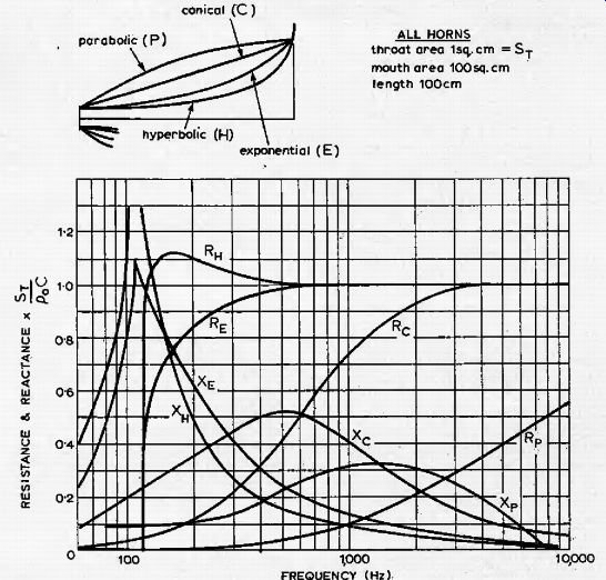
Fig. 1. Acoustical resistance and reactance against frequency at the throats
of a series of infinite horns of different contour.
Determination of flare contour
The theory of the conical hom was originally worked out by Lord Rayleigh, but the first serious attempts to establish a practical working formula for the exponential horn were not made until 1919 and the years following. The basic formulae for the transmission of sound waves through horns have been given in modem terms by V. Salmon [22] and others. Beranek [4] has plotted the acoustical resistance and reactance against frequency at the throats of a series of infinite horns of different contour with identical cfoss-section.ai areas at the throat and at a given point along the axis of the horn, and the resuiting curves are shown in Fig. 1, For optimum loading of the loudspeaker motor, it may be shown that the impedance presented by the throat of the horn should be entirely resistive and of constant value throughout the working frequency range, i.e. the sound transmission should be of unity "power factor". Examination of the curves in Fig. i shows that the exponential and hyperbolic contours satisfy this condition most closely.
However, a further condition to be satisfied is that of minimum distortion at the throat of the horn, caused by "air overload". When a sound wave is propagated in air, a series of harmonics wilt be produced, thereby distorting the waveform. This, occurs because if equal positive and negative changes in pressure are impressed upon a mass of air, the resulting changes in volume will not be equal; the volume change due to, an increase in pressure is less than that due to an equal decrease in pressure. The rapid expansion and compression: of air caused by the propagation of sound waves takes place adiabatically, i.e. there is no net transfer of heat, and the pressure and volume are related by the formula pi' 1 = constant, where
p = pressure
V = volume
y = adiabatic gas constant (approx.
1.4 for air under normal room conditions)
This curve has been plotted in Fig. 2, together with a superimposed large, sinusoidal change in pressure to illustrate the corresponding distorted change in volume.
If the horn were a long cylindrical pipe, distortion would increase the further, the wave progressed towards the mouth. However, in the case of a flaring horn , the amplitude of the pressure wave decreases as the wave travels away from the throat, so for minimum distortion the horn should flare out rapidly to reduce the.pressure amplitude as early as possible after the sound wave has left the throat. From this viewpoint it is apparent that the parabolic and conical contours will generate the least distortion due to air overload, and that distortion will be highest for the hyperbolic horn, because the sound wave must travel a further distance before the pressure reduces significantly.
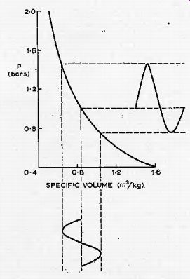
Fig. 2. Adiabatic pressure/volume relationship for air.
Further inspection of Fig. 1 shows that the. acoustical resistance of the hyperbolic horn lies within 10% of its limiting value over a larger part-of its working frequency range than that of the exponential horn, and for that reason the hyperbolic horn provides rather better loading conditions to the loudspeaker motor. However, in view of the considerably higher air-overload distortion of the hyperbolic horn, the exponential or one of its derivatives is generally chosen as a satisfactory compromise between the hyperbolic and conical contours.
In cases where the advantages of a long slow flare rate, are required, without the attendant high air-overlpad distortion, Olson, 3, has shown that a horn can be made up of a series of manifold exponential sections, commencing with a very short stub of high flare rate at the throat (to minimize distortion) which leads into a longer section of lower flare rate and thence to the main horn pf very low flare rate. Klipsch has referred to this technique as the "rubber throat" in his paper on comer horn design.
The mouth acoustical impedance of each exponential section is designed to match the throat impedance of the preceding section, right along the chain. Practically any acoustical impedance relationship with frequency may be obtained by this technique, but the procedure is complicated, and the additional effort cannot generally be justified for domestic horns.
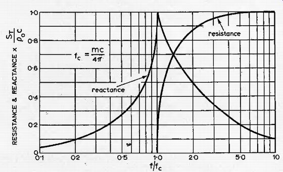
Fig. 3. Acoustical resistance and reactance of an exponential horn.
Determination of month area
The acoustical resistance and reactance of the exponential horn have: been plotted on a normalized scale in Fig. 3, which shows that the acoustic impedance is entirely reactive below a frequency given by mc
^
=
4^
where
c = speed of sound; m = flare constant which appears in the basic exponential horn formula
^ = STe m*
where Sx ..is the area at. distance x from throat ; ST is the area at the throat.
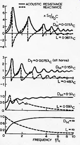
Fig. 4. Performance of foreshortened horns. Reflections at the mouth cause
peaks and troughs in the frequency response near to cut-off.
The frequency f_c known as the cut-off frequency, is the lowest frequency at which the horn will transmit acoustical power, and thus the flare constant defines, the lower frequency of transmission by a given horn. The flare constant may be calculated for any given cut-off frequency, and the horn profile may then be constructed. The above statement refers strictly only to horns of infimte length. In horns, as in cylindrical tubes, wavefronfs of. sounds whose wavelength is large compared with the mouth diameter tend to be reflected back into the horn where they interfere, with successive wavefronts. Just as the loading of the loudspeaker motor by the throat of the horn must be largely resistive over the working frequency range for the smooth efficient transfer of acoustical energy, so must be the loading presented to the mouth of the horn by the surrounding air. Beranek has shown4 that for the radiation impedance of the mouth to be mainly resistive, the relationship C'x > 1 must hold, where C is the circumference of the mouth of the horn and X is the wavelength of the lowest note to be transmitted. If the mouth of the horn is not circular, it will behave in a similar way for equal mouth areas, i.e. if C = 2nrm>Xc is the limiting condition and = nrl> X2 c An 2n where Ac = cut-off wavelength; rm --mouth radius; Sm = mouth area.
Thus a horn of square section may be employed provided the mouth area exceeds X 2
-. Hanna and Slepian had examined from 4ji
a different standpoint the behaviour of wavefronts at the mouth of the horn, and deduced that reflection was a minimum when the slope of the profile was 45° (i.e. included angle of 90°). This will be so where the mouth circumference equals the cut-off wavelength of the horn. It also illustrates the importance of distinguishing between the values of flare constant used for calculating exponential increase in area, and in plotting the profile of the actual horn.
Fig. 4 (after Olson) illustrates the effect of foreshortening the horn to
a length less than the ideal. When the mouth circumference becomes less than
the cut-off wavelength, reflections at the mouth cause objectionable peaks
and troughs in the frequency response at frequencies near to cut-off, and
if, iaa given design, the mouth dimensions are restricted, it is generally
preferable to increase the cut-off frequency to a value which allows the
correct mouth area to be adopted, rather than to accept the uneven bass response
illustrated in Fig. 4, Plane and carved wavefronts Hitherto, the assumption
has been made that successive wavefronts remain plane throughout their propagation
through the horn. However, along a straight circular section horn the wavefront
must be normal to the axis, and also normal to the walls. (If the wavefront
were either approaching or receding from the walls, energy would be either
absorbed or supplied; alternatively, the composite wavefront resulting from
the original wavefront and its reflection will itself be normal to the walls.)
Thus wavefronts transmitted along a cylindrical tube will be plane, while
wavefronts transmitted down a conical horn will be spherical. It is therefore
clear that the wavefront emerging from an exponential horn will possess a
degree of curvature, and that the conventional calculations made on the assumption
of the exponential increase of plane wavefronts will be in error (in practice,
the actual cutoff frequency will be somewhat altered from that derived theoretically,
and the profile errors of the horn are not excessive). The correct approach
to the design of a horn in which the areas of successive wavefronts expand
according to a true exponential law is not certain, since any horn profile
chosen will per se determine the contour of the wavefronts within it, and
in genera! this contour will be different to that originally assumed. Wilson" decided
to assume spherical wavefronts of increasing curvature from zero (plane wavefronts)
at the throat of the horn, and on this basis he calculated a modified contour
which lies just inside and very close to the true exponential.
Fortuitously, if a papier mache hom is made on a solid former designed to a true exponential contour, the shrinkage of the papier mache when drying converts the hom very closely to Wilson's modified form. Nevertheless, the prime assumption has been made that wavefronts are spherical and of changing curvature, and it is by no means certain that this is the case.
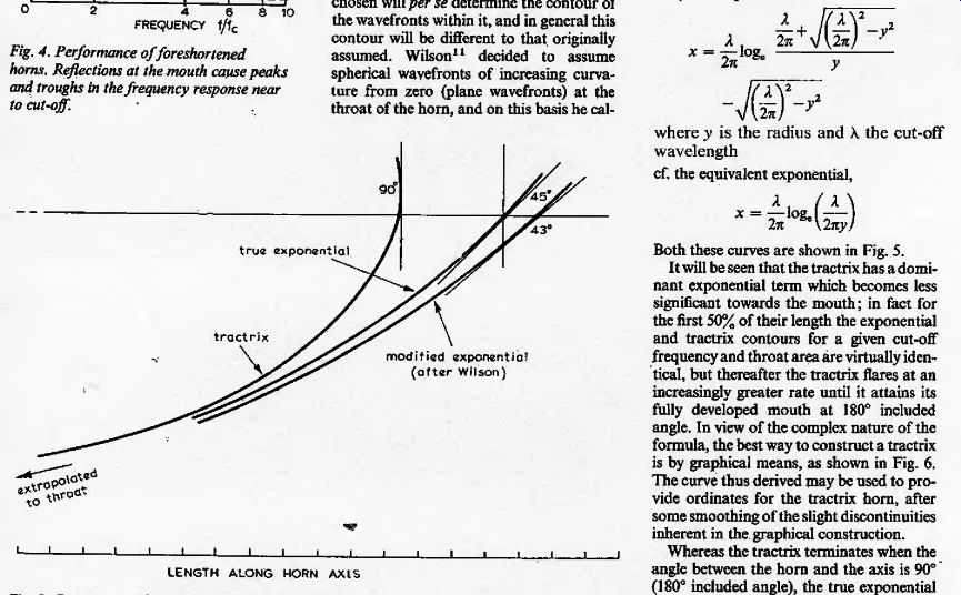
Fig. 5. Comparison of the exponential and tractrix contours.
The tractrix contour
Voigt, in his 1927 patent, had proceeded on the more elementary assumption that the wavefronts within the hom must be spherical and of the same radius throughout their propagation through the hom. He based this assumption on the reasoning that if the curvature increases from plane waves (zero curvature) at the throat to a certain curvature at the mouth, then a point on the axis must travel at a faster rate than a point at the wall. Since the entire, wavefront must travel at the speed of sound (assumed to be constant throughout the hom) the wavefront has no alternative but to be spherical and of constant radius. This requires that the hom contour should be the tractrix.
The tractrix is the involute of the catenary (the curve adopted by a uniform heavy chain suspended between two points at the same level) and is the curve traced out by a load being dragged along by a man moving in a straight line not passing through the load. It is not the "pure pursuit" curve traced by a missile which always travels towards an escaping target, as is often mistakenly supposed. The length r of a tractrix horn of mouth circumference \c, may be expressed as 2^0g
° 2jt M
-y
-Jii where _v is the radius and A. the cut-off wavelength cf. the equivalent exponential.
2nyj Both these curves are shown in Fig. 5.
It will be seen that the tractrix has a dominant exponential term which becomes less significant towards the mouth; in fact for the first 50% of their length the exponential and tractrix contours for a given cut-off frequency and throat area are virtually identical, but thereafter the tractrix flares at an increasingly greater rate until it attains its fully developed mouth at 180° included angle. In view of the complex nature of the formula, the best way to construct a tractrix is by graphical means, as shown in Fig. 6.
The curve thus derived may be used to provide ordinates for the tractrix horn, after some smoothing of the slight discontinuities inherent in the graphical construction.
Whereas the tractrix terminates when the angle between the horn and the axis is 90° (180° included angle), the true exponential goes on to infinity in both directions. The tractrix horn for given throat and mouth dimensions is thus shorter than the equivalent exponential. It has been suggested that with the full tractrix terminating in a mouth of 180° included angle, the sound appears to originate from a point just inside the mouth, where the included angle is only 90°. There is thus some evidence that the tractrix may be terminated prematurely at this point, and if this is done, the mouth perimeter will be 90% of the wavelength at cut-off, as shown in Fig. 5, which compares the true and modified exponentials and the tractrix contours.
Efficiency
The efficiency of an exponential horn loudspeaker is determined by a large number of parameters, and a comprehensive treatment has been provided by Olson.
Typical efficiencies of bass horns can be as high as 50%, while mid-frequency and treble horns can have efficiencies of over 10%, and these figures compare very favorably with bass reflex enclosures (efficiency 2 to 5%) and infinite baffles (efficiency generally less than 1%), The extremely high efficiency of the horn is not necessarily of value in enabling amplifiers of lower output power to be used.
Indeed, some class B output stages may produce a higher distortion level in horns because they need only be operated within the first 10% of their capability, at which low levels the effects of crossover distortion are more pronounced.
The principal advantage conferred by the horn's high efficiency is that for a given loudness the amplitude of movement of the loudspeaker motor is appreciably less than with other enclosures. The effects of nonlinearities in the magnetic field and suspension are therefore greatly reduced, and there is less tendency for "break-up" of the cone to occur. Thus the relatively high distortion products normally produced by the loudspeaker motor will be minimized, and, provided the horn itself does not introduce distortion, extremely high quality sound can be radiated.
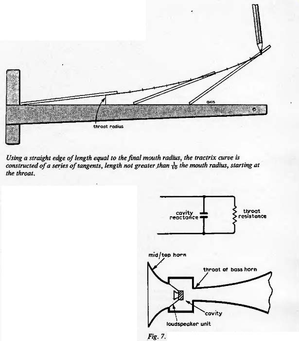
--------- Using a straight edge of length equal to the final mouth radius, the tractrix curve is constructed of a series of tangents, length not greater .than fo the mouth radius, starting at the throat.
A further advantage resulting from this reduction in amplitude of movement of the cone is that a form of inter-modulation distortion, caused by variation of the volume of the cavity between the loudspeaker cone and the throat of the horn, may be reduced to negligible proportions.
Tailing the throat cavity
The cavity, which must inevitably exist between the loudspeaker diaphragm and the throat of the horn, plays an important function in the design of horn systems, since it can be used to limit the maximum frequency to be transmitted. Although the lower frequency limit may be set with some precision by the flare rate of the horn, in conjunction with the mouth area, the upper frequency limit is ill-defined, being determined by a combination of (a) unequal path lengths between different parts of the diaphragm and the throat of the horn, (b) internal cross reflections and diffraction effects within the horn, especially when the horn is folded, (c) the high frequency characteristics of the motor unit itself, and (d) the effective lowpass filter characteristic presented by the cavity between diaphragm and throat.
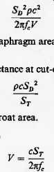
It may be shown that a cavity of fixed volume behaves as an acoustic reactance of value Stfpc 1 InjV where SD = area of diaphragm, V = volume of cavity, p = density of air, c --speed of sound,/= frequency.
When the cavity is placed between the diaphragm and throat, it behaves as a "shunt capacitance" across the throat itself, and thus by choosing the correct parameters, the cavity/throat combination acts as a lowpass filter at a frequency which may be set by making the cavity impedance equal to the throat impedance at the desired frequency,
Sppc 2
_ pcSD 2 1' e
' 2nfV ST where ST --throat area,/ = desired upper frequency limit, whence V --cST
The volume of the cavity may therefore be calculated to provide high-frequency rolloff at a point before the poorly-defined effects (a) to (c) stated above become significant (Fig. 7).
A further benefit resulting from the use of a cavity tuned to prevent mid and high frequencies from entering a bass horn at the rear of a loudspeaker is that the efficiency of transmission of these frequencies by the opposite side of the loudspeaker is greatly increased, thus improving the performance of a mid/high frequency horn mounted at the front of the loudspeaker.
The considerations affecting the practical determination of the upper and lower frequency limits of a particular horn will be considered in more detail.
Loading the rear of the loudspeaker motor
Mention has already been made of distortion resulting from the non-linear expansion/ compression characteristics of air. This effect is accentuated when a loudspeaker is horn-loaded on one side only, because the cavity " reactance" throat resistance mid/top horn throat of bass horn / cavity loudspeaker unit constant resistance characteristic of the throat acts only against excursions of the cone in the forward direction; when the cone moves back it is against a far lower load and hence the excursion will be larger. The ideal way of eliminating this distortion is to load both sides of the loudspeaker by equal horns, or to employ a bass horn for loading the rear of the cone and a middle/top frequency hom to load the front. The design of the mini-horn, to be described, utilizes this feature.

Fig. 7. Effect of the throat cavity in limiting high frequency performance.
An alternative solution favored by many designers is to load the rear of the loudspeaker by a sealed compression chamber, the effect of which is to provide a loading similar to the hom. The compression chamber thus reduces the effects of nonlinearity due to uneven loading on each side of the loudspeaker diaphragm, and also presents a better resistive load to the diaphragm because a closed chamber on the opposite side of the diaphragm to the hom itself acts as a "capacitive" reactance which tends to balance the "inductive" reactance presented by the mass reactance of the throat impedance at low frequencies.
Klipsch states that the volume of this cavity is given by the throat area multiplied by Ihe speed of sound divided by 2n times the cut-off frequency. This is readily shown as follows: The air chamber reactance is given by SD 2 pc 2 WcV where = diaphragm area, V = volume of air chamber.
The throat reactance at cut-off is pcSD 2 ST where Sr --throat area.
Equating these, F= 2 pi f However, some observers claim that the use of a compression chamber detracts from the realism of the, reproduced sound, and advocate either double horn-loading or a combination of horn-loading with direct radiation from the other side of the diaphragm; in other words, the most realistic reproduction occurs when both sides of the diaphragm are allowed to. radiate.
Summary In summarizing this section^ it is clear that there is no universal formula applicable to any aspect of horn design. The reason for mentioning the alternative approaches and for providing a comprehensive list of references is to stimulate others to experiment in those areas where to a large extent results must be evaluated subjectively by very careful comparative listening tests a posteriori.
To quote Wilson:
"It cannot legitimately be assumed that a horn incorporated in a cabinet has the precise characteristics of any particular type of straight horn, whether exponential, hyperbolic, catenary or tractrix, even though their dimensions have been used as guides in its construction. The multiple changes of direction, coupled with reflections and absorptions and internal resonances, are always such as to destroy any legitimate comparison. Every internal (horn) enclosure construction must be judged on its merits as revealed by measurement and by listening tests."
REFERENCES
1. Crabbe, H. T, "A Concrete Horn Loudspeaker System, Mk, 2". Hi-Fi News. Oct.-Nov.
1967.
2. "Toneburst'V "Low-cost Horn Loudspeaker System", Wireless World. May 1970 and Jan. 1972.
3. Olson, H. F,, "Acoustical Engineering", van Nostrand, 1957.
4. Beranek, L. L.. "Acoustics", McGraw-Hill, 1954,
5. Cohen, A. B., "Hi-Fi Loudspeakers & Enclosures" 1st Edition Rider, 1961.
6. Teifer, G., Private communication, Nov. 1972.
7. Strutt, J. W., Lord Rayleigh, "'Theory of Sound" Pt. 1, Macmillan, 1878.
8. Webster, A. G., Proc. Nat. Acad. Sci. Vol. 6 (1920).
9. Hanna, C. R. & Slepian, J., "The Function and Design of Horns for Loudspeakers", J.A.I.E.E. Vol. 23, Feb. 1924.
10. Flanders. P. B„ British Patent No. 245,4)5, 24th March 1927.
11. Wilson, P. & Webb, A. G,, "Modem Gramophones and Electrical Reproducers", Cassell 1929.
12. Voigt, P. G. A. H,, British Patents Nos. 278,098 (1927), 351,209 (1930), 404,037 (1934), 435.042 (1935). 13. Crandall, L B., "Vibrating Systems and Sound", van Nostrand, 1926.
14. Klipsch, P. W., "A Low-frequency Horn of Small Dimensions",/. Acous. Soc. Am. Vol. 13 No. 2, Oct. 1941.
15. Klipsch, P, W., "Improved Low-frequency Horn", J. Acous. Soc. Am. Vol. 14 No. 3, Jan. 1943.
16. Klipsch, P. W., "A High-Quality Loudspeaker of Small Dimensions", J. Acous. Soc.
Am. Vol. 17 No. 2, Jan. 1946.
17. Klipsch, P. W., "A New High-frequency Horn", I.E.E.E. Trans. Audio, Nov.-Dec. 1963.
18-. Klipsch, P. W., "Loudspeaker Developments", l.R.E. Trans. P.G.A., May-June 1953, 19. Crabbe, H. J,, "Design for a Folded Corner Horn", Wireless World, Feb. 1958.
20. Baldock, R.. Hi-Fi News, Vol. 11, April 1967.
21. Wilson, P. & G. L., "Horn Theory and the Phonograph", presented to 83rd meeting of Acoust. Soc. Am., April 1972.
22. Salmon V., "Generalized Plane Wave Horn Theory", /. Acoust. Soc. Am. Vol. 17 No. 3, Jan. 1946.
23. Klipsch, P. W., "Loudspeaker Performance", Wireless World, Feb. 1970. 24. Harwood, H, D.. "Speakers in Corners", Wireless World, April 1970. 25. Klipsch. P. W„ "A Note on Acoustic Horns", Proc. I.R.E., July 1945, 26. Wood, A., ThePhysicsofMusic", Methuen 1944.
27. Moir, J., "High Quality Sound Reproduction" 2nd Edition, Chapman & Hali, 1961,
-----------------------------
Basic design procedure
The previous sections have outlined the physical principles underlying the operation of horns, and have shown how, provided certain basic rules are followed, sound re^ production of startling clarity and realism is possible from horns. However, it will also be clear by now that, unless one is prepared to accept extremely large and costly structures, it is all too easy to lose many of the potential qualities of horns through attempts to reduce the size to more acceptable proportions. This section now considers the procedures to be adopted in designing a domestic horn enclosure.
It has already been stated that the horn behaves as a transformer, converting acoustic energy at high pressure and low velocity at the throat to energy at low pressure and high velocity at the mouthAs with the analogous electrical transformer in which electrical voltage and current correspond to acoustical pressure and velocity, the basic requirements of the acoustical horn are that: (a) the primary (throat) should be correctly matched to the signal source (loudspeaker motor); (b) the secondary (mouth) should be correctly matched to the load (listening room); (c) the horn should be designed to handle the specified power level and frequency range. There are four principal parameters of the horn, namely mouth area, throat area, Sare contour, and axial length.
Any three of these will determine the fourth, and hence the characteristics of the horn itself. Once non-circular cross-section and non-linear axes are adopted, the problem becomes far more complex, and mathematical and physical concepts are no longer sufficient to design a horn. Nevertheless, the basic characteristics even of folded horns are determined to a large extent by known acoustic principles, and the most effective method of design is to work from these principles, ensuring that any deviation from theory is made on scientific groumis where possible.
Flare profile
Previous sections discussed the most commonly considered flare profiles, and it was concluded that a contour which allowed an exponential increase of the area of the wavefront as it travelled from throat to mouth provided the best compromise between the extremely gradual expansion of the hyperbola (giving optimum loading of the motor, but excessive throat distortion) and the rapid expansion of parabolic and conical horns (giving minimum throat distortion but poor loading of the motor). However, the exact shape of the wavefront within a horn of curved profile is uncertain, and therefore assumptions have to be made, ranging from Wilson's modified exponential (lying a little inside the true exponential) to Voigt's tractrix, (which commences in a virtually identical manner to the true exponential, but departs substantially outside it in the region of the mouth). Which contour one adopts must be largely a matter of personal preference based preferably on careful listening experience.
Mouth geometry
The mouth of the horn couples the horn itself to the listening room. One of the commonly raised disadvantages of horns is that they require a very large mouth area if bass notes are to be properly reproduced. To some extent this is true; one cannot get a double bass out of a piccolo. However, there are a number of ways in which the mouth area may be reduced to manageable proportions without significantly sacrificing bass response.
As a sound Wavefront travels up the steadily increasing bore of the horn, it should not meet any major discontinuity. However, it is clear that, unless the length and mouth diameter of the horn are infinite, there must be some discontinuity, as the wavefront emerges and is no longer constrained by the walls of the horn. Although the cut-off frequency of the exponential horn is determined by the flare constant, the linearity with frequency of the acoustical resistance and reactance are determined by the mouth area, which, for a given throat area and flare constant will also determine the overall length of the horn. Strictly speaking, for no discontinuity, the mouth should have infinite area. However, Olson, 3, has shown that provided the perimeter of the mouth of an exponential horn is greater than four times the cut-off wavelength, i.e. pm > 4AC there will be no significant deviation of mouth resistance, from that of the infinite horn.
A more important result is that for only 6dB variation in acoustic resistance, the mouth perimeter may be made equal to the cut-off wavelength, i.e. mouth area = 42
/4jt where Xc is the cut-off wavelength.
As the mouth area is reduced below this value, the non-linearity of the acoustical resistance and reactance will increase.
Now these figures refer to the situation where the horn is suspended in free space, i.e. it radiates into an angle of 4jt solid radians. In practice, this situation never occurs: even if the horn were placed on the ground at the center of an infinite field, the mouth would only radiate into half a solid angle,: or 2ji solid radians; against the center of a wall the mouth would be loaded by % solid radians, and in a corner formed by two walls and the floor the mouth will be loaded by only %j1 solid radians. The significance of this is that, whereas the minimum mouth area for a circular horn has been shown to be X^jAn when loaded by An solid radians, this value may be divided by a factor of two each time the solid angle is halved.
Thus the mouth area may be. reduced to a size more in keeping with domestic conditions, e.g. a horn with a cut-oif frequency of 56Hz (wavelength 20ft) would require a mouth area of 32 sq ft in space, but only 8 sq ft against a wall and 4 sq ft in a comer position, to give variations in loading of less than 6dB, This situation which is illustrated in Fig. 8 may be compared with the mouth of a single horn placed at the intersection of eight rooms: four on the ground floor and four on the first floor. The bass response of the. original horn will not be impaired, even though a listener in each room will see only one eighth of the total mouth area. One seldom gets anything for nothing in this world, and those who adopt corner speaker positioning in order to obtain a purer extended bass response from as small an enclosure as possible, may have to live with the eigentones such a position produces.
A plan view: of a comer horn shows that the room itself provides a natural extension of the horn mouth. Many listeners have observed that comer homs can provide bass notes from fore-shortened homs, well below the limit dictated by the mouth area 25. It is tempting to reduce the mouth area still further below the 3dB limit established earlier and rely instead on the corner placement itself to supply the additional month area and horn length. In the author's experience, this technique cannot be justified because although the bass response is undoubtedly there, careful listening reveals an uneven response over the first two octaves above the cut-off frequency which will often detract from the realism offered by the horn.
It is therefore recommended that in cases where overall enclosure size is a limitation, a correctly-designed hom with a cut-off frequency of (say) 80Hz will give a more satisfying and linear response than a foreshortened horn whose expansion constant has been set to 40Hz but whose length has been limited to give a mouth area corresponding to 80Hz.
Most domestic horns will be of rectangular cross-section for ease and cheapness of manufacture. The foregoing comments regarding homs of circular section apply also to rectangular sections, although it is clear that the wavefront must behave in a most complex way at the corners, thereby reducing slightly the effective cross-sectional area. Provided that the ratio between the major and minor axes at the mouth does not exceed 4:3, rectangular horns may be employed to good effect.
Tabular design data is given for homs of both round and square section, with mouth areas computed for both corner positioning {n/2 solid radians) and wall positioning (n solid radians).
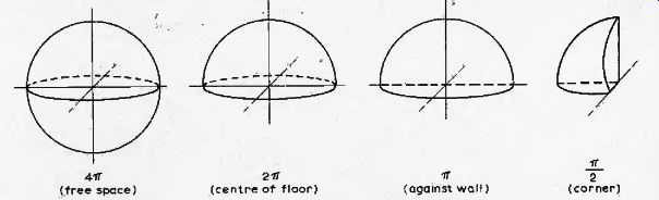
Fig. 8. Solid angles presented to a horn in different positions.
Throat geometry
The throat of the hom couples the wavefronts from the loudspeaker, which should ideally be plane at this point, to the horn itself. It has previously been shown that the horn is an acoustic transformer, converting acoustic radiation of high pressure/low velocity at the throat to low pressure/high velocity at the mouth. It is clearly of advantage to have a high pressure (and hence a low velocity) at the throat, because the low velocity will result in smaller movement of the loudspeaker cone, thus reducing the distortion produced by non-linearities in the magnetic field and the suspension, One way of increasing the pressure, and also of ensuring a higher degree of "plane-ness" of the wavefronts is to employ a throat area substantially smaller than that of the loudspeaker itself. Tests carried out on a number of loudspeakers have shown that the "equivalent piston area' --is approximately 70% of the speech cone area, i.e. the loudspeaker diaphragm in the shape of a truncated cone gives the same acoustic output as a plane piston with 70% of its area.
There are a number of practical reasons why modern loudspeakers are not manufactured as plane pistons; one of the unfortunate results , of employing conical diaphragms Is that the resulting wavefronts are in general hot planar. However it has been found empirically that a throat area of between one quarter and one half the "equivalent piston area" of the loudspeaker provides satisfactory coupling between the loudspeaker and the hom, and also gives an approximation to plans wavefronts at wavelengths well in excess of the throat dimensions. It must be emphasized that for higher frequencies, where the wavelengths are of the same order as the physical dimensions of the loudspeaker diaphragm, the throat area should be made, the same as that of the loudspeaker, and the hom should be of circular, section, at least at the throat, so as to minimize standing waves across the hom itself.
The phenomenon of air overload distortion is caused by the non-linear relationship between pressure and volume of the air in the throat of the horn as it undergoes adiabatic compression and expansion. Beranek4 has derived the relationship for 2nd harmonic distortion at the throat of an infinite exponential horn as:
% 2nd harmonic distortion
= UXflfcVf' x 10-2 where / --driving frequency f = cut-off frequency /, = intensity (watts/sq m) at the throat.
This expression is also closely correct for finite horns because most of the distortion occurs near the throat. This expression has been plotted in Fig. 9 from which the throat area for given power and distortion may be obtained, It is important to appreciate that the acoustic power radiated by musical instruments is extremely small 26 , and that the higher the frequency the lower is the acoustic power to give the same subjective effect at the human ear. With the exception of full orchestra and pipe organ, which in the author's view it is futile to attempt to reproduce in domestic surroundings at anything approaching normal volume level, the acoustic power levels are extremely small and an aim-point of (say) 3 watts and 1% distortion at the cut-off frequency, reducing to 0.05 watts and 0.5% distortion at four times the cut-off frequency, is likely to prove entirely satisfactory for domestic listening. The above proposals for power and distortion give a throat area of around 10 sq cm, from Fig. 9, which compares not unfavourably with the effective piston area of 43 sq cm for a 3 in loudspeaker, one quarter of which is a little over 10 sq cm. Of course, if the throat area is increased, as would be the case with larger loudspeakers, the available power for a given level of distortion will also increase.
Having established the throat and mouth areas and the flare profile, the length of the horn and hence its area at any point may be obtained mathematically or graphically.
The horn as a filter
The foregoing sections have indicated how the horn can act as a bandpass filterthe lower pass frequency of which is determined by the expansion coefficient and the upper by the volume of the cavity between the loudspeaker and the throat of the horn. It is important that the response should be as linear and free from distortion as possible over this passband, and as far as the lower frequencies are concerned, careful choice of mouth area, in conjunction with a knowledge of the solid angle into which the horn will radiate and the flare constant, can ensure that non-linearities in the frequency response are kept to a satisfactorily low level.
However, with regard to higher frequencies, non-linearities of increasing amplitude become apparent at frequencies exceeding about four times the cut-off frequency, due to internal cross-reflections and standing waves set up within the horn itself. These non-linearities will be more serious if the material of which the horn is constructed can resonate, and they are also accentuated if the horn is folded, when wavefronts at the higher frequencies will be distorted at bends.
In fact, there is also a practical limit beyond which folding becomes undesirable; folding should not occur beyond the point at which the lowest wavelength (highest frequency) to be transmitted exceeds 0.6 of the diameter of the horn. More will be said of this limitation during the discussion on folding, but it clearly points to a practical limit on the highest frequency a horn may accurately transmit.
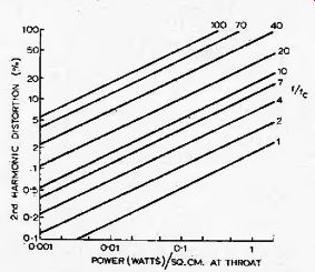
Fig. 9. Distortion caused by air overload at the throat.
Yet a further limitation becomes apparent from the graph of throat distortion versus frequency (Fig. 9). As the frequency increases, the percentage distortion for a given power density at the throat wilt also increase, and althougii it is generally true that in the majority of complex musical sounds the energy level reduces with increasing frequency there will still be a frequency above which throat distortion becomes unacceptable.
A commonly used and quite adequate rule of thumb is that a horn should not handle frequencies higher than four octaves above its cut-off frequency, although purists may prefer to limit at only three octaves in order to ensure lower distortion levels.
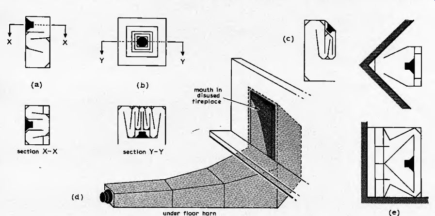
Fig. 10. Methods of folding horns (a) Olson, (b) Olson and Massa, (c) Lowther,
(d) Newcombe, (e) Klipsch.
The complete multi-horn system
The maximum frequency range to be handled by a wide-range high-quality loudspeaker is about 9 octaves, i.e. 40Hz to 20kHz. This is clearly too wide a range to be handled by a single horn, for the reasons already noted, but it can conveniently be divided into three ranges, i.e. 40Hz to 320Hz, 320Hz to 2.5kHz and 2.5kHz to 20kHz. In practice, a 10% overlap should be allowed to ensure that there are no troughs in the response at the crossover points, and a case could be made for a fourhom system to cover a wider range.
It is also worth considering a more modest instrument. If the cut-off' frequency is limited from 80Hz to 18kHz and a two-horn system is considered with each horn handling a little under four octaves , the frequency ranges become 80Hz to l'.2kHz and f,2kHz to 18kHz. Again, about (0% frequency overlap should be allowed.
The great attraction of a two-horn system is that only a single loudspeaker is required: the bass horn will be loaded from the rear of the loudspeaker; while the middle and treble horns will be loaded from the front of the loudspeaker, to eliminate interference and diffraction effects caused by the frame and magnet assembly at lower wavelengths.
It has already been emphasized that the throat of the horn should match exactly the loudspeaker dimensions at these higher frequencies, and this arrangement is particularly attractive if a twin-cone speaker is employed. Treble wavefronts may be prevented from going down the bass horn by the cavity. To show the ease and utility of this approach, this article includes the design of a "mini-horn" utilising both sides of a single loudspeaker in a cabinet of reasonable size and cost for small domestic living rooms.
Purists may claim that the curtailed frequency range of 80Hz to 18kHz is inadequate. It is however the author's experience that the flat relatively distortionless response between these limits, together with the sense of presence afforded by the horn's transformer action, make the mini-horn sound more attractive than many commercial loudspeaker systems of similar size but two or three times its price.
Once one adopts a multi-horn approach, there will be a number of frequencies which fall within the compass of two horns, i.e. 320Hz and 2.5kHz in the case of the threehorn system, and 1.2kHz for the two-horn system. It is essential that the radiation from the relevant pair of horns should be reasonably in phase at the crossover frequency, to avoid the presence of troughs in the frequency response, because the bass horn will be folded to bring its mouth adjacent to the other horns (it is not normally necessary or desirable to fold the middle and treble horns). This requirement places a restriction on the length of the horn, which has until now apparent that the difference in lengths of the lower horn of each pair should be either an odd or even number of half wavelengths of the crossover frequency, depending on whether the radiation wavefronts at the throats of the two horns are respectively in or out of phase.
Thus, if separate loudspeakers are used and the voice coils are connected in phase, the difference in lengths of the horns from the loudspeakers to the plane of the mouths should be an even number of half wavelengths. Conversely, if a single loudspeaker is used to feed twohorns, the radiation from the front and rear of the cone will be out of phase and the difference in lengths of the two horns should be an odd number of half wavelengths. In practice, the lower horn will be considerably longer than the upper, and will effectively determine the design.
Folding, cabinets and room placing
Hitherto, discussion has been confined to ideal horns, of circular cross-section and straight axis, constructed of very stiff material. Although typical dimensions for practical horns have not been calculated formally, it will be clear from many of the tables and diagrams that the dimensions of bass horns are almost certainly too large for comfortable accommodation in an average living room. Two further points must therefore be added to the design procedure, adoption of rectangular sections and folding the horn into a compact size.
Rayleigh showed that bends in tubes of constant cross-section will have no effect on transmitted sounds if the wavelength is large compared with the diameter, but that any cross vibrations set up will have a fundamental wavelength of 1.7 times the tube diameter. Wilson, 11, has summarized the three principal rules of folding horns as follows: the wavefronts must not be twisted across the horn; the horn diameter (or width if rectangular) must be less than 0.6 times the lowest wavelength to be transmitted by that horn; the wavefront should be accelerated round bends to preserve its form.
As soon as one departs from the straight horn of circular cross-section, the scientific design principles described cease to be so relevant and become of more approximate value, although the three basic rules quoted above, together with the choice of a suitably stiff material for construction, provide very acceptable results.
A folding technique which twists the wavefront across the horn is difficult to achieve in practice, and may be eliminated by folding always in one plane. The requirement to "accelerate the wavefront around bends to preserve its form" is difficult to achieve when more than one fold is involved, since it requires a rectangular cross-section before the bend to become trapezoidal around the bend itself 1 and then revert to a different rectangular section after the bend. If one considers a multi-fold hom, concertina-fashion within an overall rectangular enclosure, this is not really a practical proposition, and is unnecessary because subsequent bends correct the waveform.
But for single bends it can be adopted, and the mini-horn design described later could utilize this feature.
Examination of the Patent Office records for folded horn designs registered during the 1920s and 30s provides a fascinating monument to the ingenuity of acoustical designers, and Fig. 10 illustrates a number of the more well-known methods of folding.
The restriction of horn width at a bend to 0.6 times the highest wavelength to be transmitted suggests initially that folding can only be attempted over the first few feet of the length of a horn; after that point the width will have reached the limiting value.
However, this limitation may be overcome by bifurcating the horn (splitting into two equal channels) at each point when the width limits. Thus the mouth of a horn may comprise four equal mouths (brought together for convenience and to ensure audio realism) and the four "quarter-horns" may be folded far closer to the mouth than would otherwise be possible. Rayleigh has shown, 7, in Art. 264 that bifurcating a conduit will have no effect on the transmission of sound provided the lengths of the two portions are equal and the sum of their areas at corresponding points is equal to that of the original conduit.
In many cases, the front side of a loudspeaker, whose reverse side is horn loaded, will be physically close to the mouth of the horn itself, and it is commonly feared that there will be concellation at certain frequencies caused by interference between the two radiations in anti-phase. However, the direct radiation from the unloaded front of the cone i s only a few percent of that.thro ugh the horn, and so the amount of cancellation is negligible.
Frequency handling
Although it has been shown that each horn acts as an acoustic bandpass filter, the lower cut-off frequency being determined by the expansion coefficient and the upper cut-off frequency by the throat cavity, there are important reasons why the full audio signal should not be applied directly to all horns regardless of their frequency handling capability. At the low frequency end of the spectrum, examination of Fig. 3 (Part 1) shows that the horn provides the loudspeaker with no resistive acoustic loading below its cut-off frequency. Thus any applied signals below this frequency will cause excessive movement of the loudspeaker diaphragm, which will be constrained only by the mechanical and electro-magnetic factors. This excessive movement can cause unpleasantly high intermodulation distortion, and can also lead to further non-linear distortion when the loudspeaker moves outside its linear range. At the upper frequency end, signals of excessive power can also give rise to distortion products due to deficiencies in the cavity/throat relationship.
It is therefore beneficial to restrict the bandwidth of the electrical signal reaching each loudspeaker to match the acoustic bandwith of its corresponding horn.
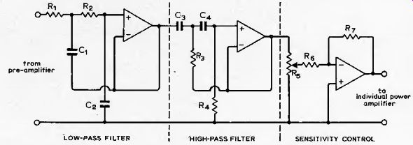
Fig. 11. Circuit for an active filter network. See appendix for component
details.
Although most commercial multi-unit loudspeaker systems use passive LC crossover networks between power amplifier and loudspeaker to route signals of the appropriate bandwidth to each loudspeaker, careful comparative listening tests show that these networks undoubtedly introducea "dullness" or loss of "brilliance" into the audio output. Many explanations have been offered for this situation; in the author's opinion, the most likely reason being the loss of "direct drive" from the output of the amplifier, allied with a significant reduction in the degree of electro-magnetic damping afforded by the low output impedance of the amplifier.
Recent correspondence: in Wireless World and elsewhere.has. extolled the virtues of splitting the frequency range at low signal level, and employing a separate power amplifier directly coupled to each loudspeaker. The author has devised such a circuit, which consists of three (or four) parallel frequency-selective channels comprising Sallen & Key active filters giving preset low and high-pass characteristics in series in each channel, together with some gain adjustment to allow for the inevitable differences in sensitivity of each loudspeaker/horn combination. The active filters provide 2nd order Butterworth characteristics, a response which appears to give the least displeasing effects at the cross-over frequencies. (There will inevitably be phaseshifts associated with any filter circuit, and the effects of these on transients caii produce a marked difference in their character.) This circuit is in Fig. 11 and the Appendix.
Thus, some form of electrical cross-over is generally necessary in addition to the acoustic cross-over provided by the horn itself. An exception is of course the case where a single loudspeaker drives two horns; one loading the front and one loading the rear of the diaphragm. In this situation, some compromise will be necessary in the acceptable distortion level and bandwidth of the loudspeaker.system.
Directional horns
This article has extolled the ability of the horn to propagate wavefronts that are nearly plane at its mouth. However, there are situations where it is desirable to propagate wavefronts with different characteristics in the vertical and horizontal planes, particularly when middle and treble horns are used in stereophonic systems; it is often desirable to spread the wavefronts in the vertical plane while preserving more of a "point-source" in the horizontal plane.
There are a number of different techniques for achieving this, based on diffraction and refraction effects at the horn mouth with the comparatively short wavelengths (a few inches or less) with which these high frequency horns are concerned.
The design , and manufacture of multiceilular horns, distributed-source horns, diffraction horns and reciprocal-flare horns is beyond the scope of this article, and with the exception of the first two mentioned is probably outside the capability of most amateur constructors. Those interested should refer to the papers by Smitlri 9, Winslow and to the relevant chapters by Olson and Cohen . Klipsch has described the design of his high frequency horn, in which the length/breadth ratio of the (rectangular) mouth assumes a value in excess of 4:1 c.f. the ratio of near unity advocated for bass horns). The optimum dimensions, length/ breadth ratio, and apportionment of flare to the long and short axes. depend on a number of complex factors, however, an aspect ratio between 2:1 and 4:1 with the flare apportioned in similar ratio has been found to give good practical results, and these parameters have been adopted for the "no-compromise horn" to be described.
Although the high frequency horn of the "mini-horn" system is. specified as circular (in view of its handling the relatively large wavelengths at 1kHz) an alternative rectangular mouth with aspect ratio of 2.5:1 has also been described.
Detailed design procedure
The previous sections have dealt in some detail with the basic theory of the born, and the essential design procedures have been outlined for a series of horns which can cover the complete, audio range. The fina! sections will consider the detail design of two horns: a "mini-horn" and a "nocompromise horn". Because all horns are designed to slightly different requirements, and inevitably many readers will wish to "bend" the specification to a greater or lesser extent in order to satisfy their own needs, the designs are presented here by means of tables so that they represent a comprehensive design code for a wide range of horns.
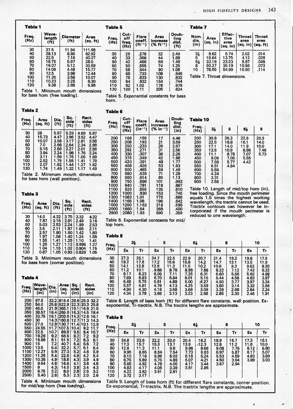
Bass horn design
The bass horn should be examined initially, commencing with the mouth. Tables 1, 2 and 3 indicate the relationship between minimum frequency and mouth dimensions for horns positioned in free air (4n solid radians) at a wall (it solid radians), and in a comer (7t/2 solid radians). In table 1, the speed of sound has been taken as 1125 ft/ sec, and the mouth perimeter as the wavelength. The mouth areas in tables 2 and 3 are equal to ^ and J respectively of the mouth area in free air, and the dimensions for the circular, square and rectangular mouths are derived from these areas. It is tempting to reduce the areas of the square and rectangular horns so as to give a perimeter equivalent to the wavelength (suitably scaled for wall or comer positioning) but this is not recommended. However, the shorter side of the rectangular horn has been derived in this way (i.e. a square horn with this side would have the appropriate, perimeter).
After settling the mouth dimensions, the throat may be determined from the chosen loudspeaker unit. Table 7 gives suggested throat areas for five typical mean, loudspeaker sizes. In some designs, the choice of loudspeaker will be influenced by considerations of overall size (the length of the horn is greatest for the smallest loudspeaker) and whether the loudspeaker is to perform as both bass and mid/top driver, using two separate horns on either side. Many loudspeakers will possess different dimensions, and in these cases table 7 will be of little value. The effective area (piston area) has been taken as 0.7 of the area derived from the mean (quoted) diameter, and the throat area as 0.3 of the effective area. Although there is obviously scope for experiment here, the quoted dimensions should give very acceptable results,
Having decided the throat and mouth areas, tables 8 and 9 give the overall lengths of homs with true exponential and tractrix contours for both wall and corner placing for homs. with the five derived throat areas at each of the cut-off frequencies specified in table 1. The factor of 1.2 applied to the cut-off frequency in table 5 when calculating the flare coefficient is to ensure a fairly linear frequency relationship throughout the working range of the horn. The flare coefficient m is thus given by m = (4nle)(fl\.l)
where c is the speed of sound (1125ft/sec)
and / is the lowest frequency to be reproduced.
The area increase is given by --and the doubling distance by (logjiym for each frequency . The length of the exponential horn is given by (l/m) SJST for each specified set of areas, and the length of the tractrix horn will be rm(l-log,,2) shorter than the true exponential, where Sm --mouth area, ST = thtoat area, rm = mouth radius.
N.B. The tractrix lengths given in tables 8 and 9 are approximations, being based on the fully developed tractrix referred to the flare cut-off frequency, whereas the mouth radius is referred to the lowest bass frequency to be reproduced.
Middle top horn design
Attention should now be directed to the huddle and high frequency horns. The mouth perimeter should not be less than the wavelength of the lowest working frequency, and in practice a perimeter of i .5 times the lowest working frequency has been found to give good results. Table 4 is based on this factor of 1.5, and gives the recommended minimum mouth dimensions for free air loading. It is safest to assume free air loading to apply at these higher frequencies, because diffraction and reflection effects at short wavelengths prevent true wall or comer loading from being achieved, and it is for this same reason that the perimeter has been specified at 1.5 times the wavelength of the lowest working frequency. The dimensions of square and rectangular horns have been derived in the same way as those in tables 2 and 3. The throat dimensions of middle and high frequency horns should match.the drive unit directly, and niay be taken as the mean diameter and area of the chosen loudspeaker, shown in table 7.
Tables 6 and 10 give the flare constants and lengths of exponential horns assuming the throat and mouth dimensions of tables 7 and 4 respectively.
--------- Tables
Integration of multiple horns
It has been emphasized that the radiation from the mouths of each pair of horns at their common crossover frequency should be iii-phase, Assuming that the mouths of all the horns will lie in the same plane, the difference in length of each pair of horns should be compared withthe multiples of half wavelengths of the crossover frequency set out in table 11. [f the drive signals at both throats are in-ph.ase (separateloudspeakers), the. difference in length should, be an even number of half-wavelengths; if the drive sigrials are out-of-phase (single speaker hornloaded at both front and rear) the difference in length should be an odd number of half wavelengths. If necessary, small changes may be made to the crossover frequency (with subsequent re-design of the higher frequency horn) to ensure optimum conditions at crossover.
Table II. Multiples of half wavelengths (ft).
The complete design
The bass horn will generally be folded.
Originally it was intended to provide a table giving the maximum permitted length of horn before folding should cease because the horn diameter has become equal to 0.6 times the lowest wavelength to be transmitted. However, examination has shown that at frequencies up to five times the bass cut-off frequency (i.e. 4 octaves bandwidth) this restriction does not apply to the comerpositioned horn (due to the small mouth dimensions) and with the wall-positioned horn the limitation lies between 92% and 95% of the full exponential length. It may therefore be assumed that provided the wall-positioned horn is not folded within the final 10% of its length, the problem of cross reflections will not arise.
Finally, the cavities at the throats of the lower frequency horns should be designed in accordance with the formula already given, remembering to allow for the loss of cavity volume due to the frame, magnet and cone assembly of the loudspeaker itself.
The design procedure laid down in this part has been applied to two different designs of horn to follow, and further examples of overall horn design are given in refs 34 to 37, and also in ref. 5.
Appendix
A variable bandpass active filter for feeding a 3 hom loudspeaker system (see Fig. 11):
REFERENCES
28. "Biamplitier Loudspeakers", correspondence in Wireless World, Mar., May, June Auc Sept., 1973.
29. Smith, R. H., "A Distributed-Source Horn", Audio Engineering, Jan. 1951.
30. Winslow, "Two-way Speaker System", Audio Engineering, Nov. 1947.
31. Sanial, A. J., "Graphs for Exponential Hom Design", RCA Review.
32. "The Design of Acoustic Exponential Horns", Electronic Engineering, Sept. 1947.
33. Newcombe, A. L., Jr., "Home Installation, Design and Performance of an Exponential Low-frequency Horn", IEE Trans, Audio & Electro-acoustics, Vol. AU-15 No. 4, Dec. 1967,
34. Massa, F., "Loudspeakers for High Fidelity Large-scale Reproduction of Sound", J. Acoust. Soc. Am., Vol. 8, Oct. '1936.
35. Olson, H. F. & Hackley, R. A., "Combination Horn and Direct Radiator Loudspeaker", Proc. I.R.E., Vol. 24, No. 12, Dec. 1936.
36. Olson, H. F. & Massa, F., "A Compound Horn Loudspeaker", J. Acoust. Soc. Am.. Vol. 8, July 1936.
37. McProud, C. G., "A New Corner Speaker Design", Audio Engineering, Jan./Feb. 1949.
38. Keele, D. B., Jnr., "Optimum Hom Mouth Size".
39. Gilliam, J. R., "Optimising Horn Loudspeaker Performance".* * Papers presented at the 46th Convention of the Audio Engineering Society, New York, Sept. 1973.
-------------
Constructional principles
Much has been written about the best methods of constructing loudspeaker enclosures, especially regarding rigidity and the prevention of resonances and leaks, and as far as the horn is concerned, these points are equally important. The horn enclosure has to stand up to considerable acoustic stress, and any shortcomings in its manufacture are liable to cause more serious aural distress than would be the case with some other enclosures.
Ideally, the horn sh ould be cast in circular section, but this form of construction is only practical with small middle and high frequency horns. The technique best adopted by the home constructor is to castinplasterof-Paris using a plywood mould and reinforcements as necessary. The calculated profile should be set out using plywood templates held in place by stringers, which will be buried within the casting itself as "reinforcement". It is also a good plan to provide a yin panel at the throat end for mounting the loudspeaker, and a further panel surrounding the mouth which will help in securing the complete horn assembly and fixing any decorative cloth finish.
Bass horns are almost invariably constructed of flat panels cut so as to approximate to the correct flare profile. Plywood, chipboard or blockhoard are satisfactory, either j or yin thick. Composite sand-filled panels consisting of two thin walls of ^in plywood spaced } or lin apart and filled with dry sand provide extremely rigid resonance-free enclosures. Great care should be taken to prevent any particles of sand, sawdust, etc. from entering the speechcoil gap of the loudspeaker; a recent demonstration mounted by the author at St. Albans was spoiled by distortion caused by a minute particle of wood in one of the treble loudspeakers. Care must also be taken to ensure that the sand is dry, otherwise the wood panels will rot. It is advisable to bake the sand on shallow trays in an oven to ensure that all moisture is removed. After filling, a few minutes of organ music will help the sand to settle down ready for "toppingup". The wooden panels should be fixed together using wood-screws and with a liberal application of a liquid glue along all mating faces. This not only adds strength, but also makes all the joints air-tight. Further strength should be provided by triangular corner fillets and "glue-blocks" placed at intervals along the longer joints. In additiOn, smaller reflecting plates should be placed at the outside of all sharp corners to "ease" the wavefronts around bends, and to help preserve the steady exponential increase in horn area, as indicated in Fig. 10.
Manufacturing tolerances should not exceed + ^in at the throat but errors of yin at the mouth of the bass horn are unlikely to have any noticeable effect on the performance. It is worth bearing in mind that the velocity of sound, on which ail design calculations are ultimately based, itself varies by as much as 5% at climatic extremes.
A vital detail is to ensure that the loudspeakers can be fitted and removed easily, maintaining an overall air-tight construction by means of thin rubber gaskets if necessary. It should of course be remembered that the highest pressures occur at the throat, and the greatest effort to ensure rigidity and absence of leaks should be made in this area. As the cross-sectional area of the horn increases, it is a good plan to fit longitudinal stiffening panels, made of jin plywood, across the center of the horn, thereby converting the horn into two symmetrical adjacent ducts. This reduces air turbulence effects at bends and makes the bends themselves less critical in addition to providing extra cross-bracing between panels that might otherwise resonate. It is worth fitting longitudinal stiffeners for the final 25% of each bass horn.
Unlike the majority of loudspeaker enclosures, there is no need to provide any sound absorbent material within the enclosure itself (except within the compression chamber, if fitted, which may be lined with acoustic wadding, long-hair wool, etc., to absorb high frequency sound). The interior of the horn should have all sharp edges removed with sandpaper and all internal corners filled with putty or a similar setting plastic compound and smoothed down by means of a finger. This practice, which is not mandatory, also has the effect of sealing any remaining air leaks. The whole interior surface should be treated with a thick coat of gloss paint.
Design of a "mini horn"
The intention of the mini-horn is to provide as many as possible of the benefits of horn-loading within an enclosure which is sufficiently small for use in a small living room, where the overall size is of course especially important when a quadraphonic or even a stereophonic installation is under consideration. The room for which this particular mini-horn was originally designed imposed limitations of 20in as the maximum intrusion into the room, and an overall height of 4ft; fortunately, corner positioning was acceptable.
It was clear that only one loudspeaker could be used, and after some thought, the Eagle FR65 was chosen. This is a coaxial twin-cone loudspeaker in which the inner (tweeter) cone is itself shaped as a small horn. This subsidiary cone will handle the extreme top of the frequency range and beam it out axiaiiy through the treble horn.
The loudspeaker has a nominal diameter of 6-5in, a frequency range of 35 to 18,000Hz and power handling capacity of 10 watts. It is clear that, since top frequencies will be dealt with by the tweeter cone, the bass horn need only cover 3 octaves, i.e. from 70Hz to 560Hz, and the middle-frequency horn can take over at (say) 500Hz. This middle-frequency horn will be most efficient for 4 octaves, i.e. up to about 8 kHz, at which point the tweeter cone will already be taking over. The complete frequency spectrum will therefore be:
Bass horn 70Hz to 650Hz
Middle horn 500Hz to 8000Hz
Top horn (tweeter cone) 8kHz upwards
The other design consideration at this stage is the power handling capacity. A bass power of 0-3 watts at a distortion level of up to 1 % was decided, Bass horn
In order to derive the greatest benefit from comer-positioning, the mouth of the bass horn should be at floor level and should stretch horizontally from wall to wall. A mouth consisting of a quadrant of a circle of I9in radius was considered, giving a horizontal arc of 2-48ft. Examination of Table 3 (Part 2) shows a minimum mouth area of 2-56 sq.ft for a horn capable of reproducing down to 70Hz, and dimensions of 2-48ft X I'03ft (29-7in X 12.5in) were therefore chosen for the bass horn.
Table 7 suggests a throat area of 0-048 sq.ft (i.e. 45 sq.cm) and Fig. 9 indicates that for 1% distortion at 7 times the cutoff frequency (i.e. 490Hz) the power at the throat will be 0-007 watts/sq. cm, giving 0-3 watts total, which is the specified value.
Table 9 shows that the bass horn will have a length of 6-18ft (exponential contour) or 5-24ft (tractrix contour). It was decided to adopt the tractrix so as to give a shorter overall length, and the complete contour has been constructed in Fig. 12.
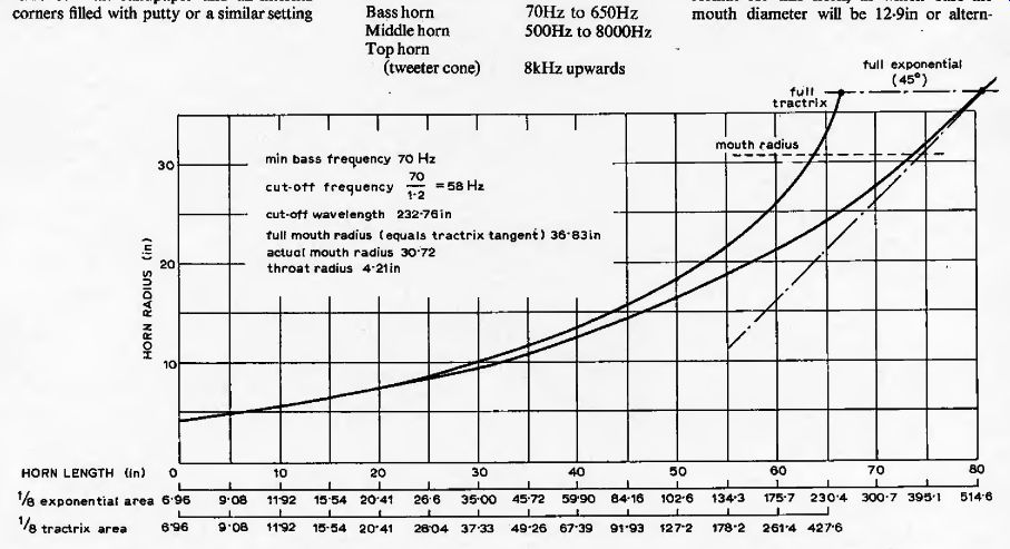
Fig. 12. Flare contour for the bass section of the mini-horn.
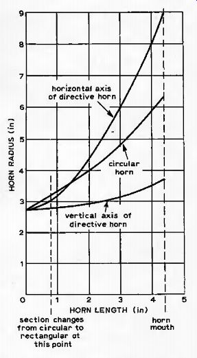
Fig. 13. Flare contour for the treble section of the mini-horn.
Treble horn
The treble horn will load the front of the loudspeaker, commencing at the nominal diaphragm area of 23 sq.in, which is thus the throat area for this horn. The lowest frequency to be handled is 500Hz, and from Table 4 the mouth area is 130-7 sq, in, which may conveniently be realized as 10-lin X 12-9m. Table 10 now gives the horn length as 4-42in.
It is also possible to adopt a circular format for this horn, in which case the mouth diameter will be 12-9 in or alternfull exponential ativeiy some degree of horizontal directivity may be introduced by adopting an aspect ratio of 2-5:1 (larger dimension horizontal). In this event the mouth dimensions become 18-08in X 7-23in, and the flare contours should be arranged to give the appropriate expansion (see Fig. 13), Integration and complete design
Radiation at the throats of the midfrequency and bass horns will be in antiphase, since these horns load the front and back respectively of the single loudspeaker.
Since the mouths of both horns will be in the same vertical plane, the difference in length should be an odd number of half-wavelengths at the crossover frequency to ensure that radiation from both mouths is in phase at this frequency. The lengths are 5.24ft and 0.37ft, giving a difference of 4.87ft. At 580Hz this length corresponds closely to five half-wavelengths as shown by Table 11. This design thus includes a satisfactory combination of horns.
The cavity which couples the rear of the loudspeaker diaphragm with the throat of the bass horn should now be designed to cut off radiation from the bass horn at 650Hz.
V^cSJlnf
where F= cavity volume, S, = throat area, /= cut-off frequency, whence V23 cu.in. The volume taken up by the magnet, etc, of the loudspeaker is approximately 21 cu.in (obtained by direct measurement) and thus the overall cavity volume will be some 44 cu.in. In many cases the minimum space necessary to enclose the rear of the bass loudspeaker apparently exceeds the optimum cavity volume for giving the correct upper cut-off frequency, often by a factor of four or five times. Since the cut-off frequency is inversely proportional to the cavity volume, this will have the effect of giving a serious "trough" in the overall frequency response before the mid-frequency horn takes over. The answer is to reduce the cavity to the correct volume by means of a circular plaster or wood moulding leading from the rear of the loudspeaker diaphragm to the throat of the horn. This technique has been well described by Crabbe (ref. 19), and is illustrated in Figs 15 and 16. The parameters of the mini-horn have been summarized in Table 12.
Finally, the bass horn should be folded into a suitable shape, and the two horns integrated together. In view of the limited space available and the desire for simplicity, a design with only one major fold may be adopted, shown in Fig, 14(b) {overpage). The mouth of the bass horn is at the bottom of the enclosure between the two walls, making contact with the floor. The mouth of the mid-horn is placed immediately above this, in the same plane, leading back to the loudspeaker itself.
The loudspeaker is mounted on a small baffle board which supports the middlefrequency horn at the front and the cavity coupling to the throat of the bass horn at the rear. The bass horn bends vertically upwards almost immediately after the throat to a point some 4ft high at which it doubles back on itself down the corner of the room to form the mouth. The cross sectional area may conveniently be made trapezoidal, but the design shown will not preserve "plane-ness" of wavefronts around the bends. Fig. i4(b) {overpage) illustrates the general arrangement only, as readers may well wish to make modifications for persona! reasons.. The material used should be -j-in chipboard, etc, except the side and front panels of 1-in plywood.
Design of a no-compromise horn Following the many qualifications already stated in this article, it must be clear that "no-compromise" is in itself a misnomer -horn design consists largely of making the most effective compromises between conflicting requirements. However, this design is aimed at the situation where the best possible practice can be followed without being unduly hampered by limitations of either size or position. Nevertheless, it would be somewhat pointless to design an enclosure which cannot be built without professional tools, facilities and materials, so the design has been conducted with a large living room (or small hall) in mind, and directed towards the competent do-it-yourself enthusiast.
In order to cover a wide frequency range, a three-horn design has been adopted, using three separate loudspeaker units.
Bass Horn 40Hz to 400Hz
Mid-frequency Horn 350Hz to 3.8Hz
Treble Horn 3-5Hzto20Hz
A total acoustic power handling capacity of 1W at a distortion level up to 2% has been chosen as being more than adequate for the situation envisaged. A wallmounting design is adopted, using a tractrix bass horn, to simplify the eventual positioning of the system. (Of course, there is no reason why a design intended for wallmounting should not be placed in a corner but it is not recommended that corner designs be placed against a wall.) The ..choice of loudspeaker drive units is not straightforward; there are many commercial units worth using in horns, although individual designers inevitably have their own favourites. For this design it was decided to use:
Horn Unit PowBrlWl
Frequency Diaphragm Range Area (Hzl (Nominal sq.in)
20-1k 42 30-5k 13 3k-30k 1-5 Bass KEFB139 30 Middle KEFB110 15 Treble KEF 127 6 Bass horn
The mouth area for a minimum frequency of 40Hz is given in Table 2 as 15-73 sq.ft, realized as 47in by 48in. The diaphragm area of the B139 loudspeaker is approximately 42 sq.in (the diaphragm is oval in shape) which corresponds closely with the Bin speaker of Table 7, This table gives a recommended throat area for the bass horn of 0-073 sq.ft (68 sq.cm). The highest frequency to be handled by this horn will be 400Hz, i.e. 10 times the cutoff frequency. Fig. 9 shows that for 2% distortion at 10 times the cut-off frequency, the throat will handle 0-01 watts/sq.cm, which for a mouth area of 68 sq.cm gives 0-68 watts total power. The length of the bass horn, from Table 8, is 13-1 ft using the tractrix contour, and this curve may be constructed to a suitable scale in the same way as that produced for the mini-horn. The form of the tractrix should commence with a throat radius equivalent to four times the chosen throat area (eight times in the case of the corner horn) and terminate at a mouth radius giving a perimeter equal to the cut-off wavelength. The area at a series of points along the horn (e.g. every 6in) may be obtained by reading the radius from the graph and taking one quarter of the corresponding
Table 12 Summary of mini-horn parameters
Fig. 14 (a) Suggested realization of the no-compromise horn (b) suggested realization of the mini-horn.
Cross sectional details for the mini bass horn are given in Table 14 and for the no-compromise bass horn in Table 15.
Middle horn
Attention should now be directed to the mid-frequency horn. The cut-off frequency of 350Hz, together with the area of the chosen loudspeaker (13 sq.in) result in a mouth area of 266 sq.in, a throat area of 13-75 sq.in and a length of ]0.9in (exponential contour). Again the contour should be constructed to a suitable scale (which may be 1:1 for the mid-frequency and treble horns). Since the throat areas of the middle and treble horns are made equal to their respective loudspeaker diaphragm areas, there is no problem regarding air overload distortion-one could do little if there were.
Treble horn In view of the throat area of 1-5 sq.in for this horn, it is suggested that a mouth area of (say) 30 sq.in is adopted, giving an exponential length of Min.
However, at these frequencies it is quite acceptable to mount the loudspeaker directly onto a flat baffle board without any horn.
Table 13 Summary of no-compromise horn parameters
Tabie 14 Cross section details for the mini bass horn
Integration and complete design
The three loudspeaker drive units should drive their respective horns in phase.
Initially it will be assumed that, whereas the middle and treble horns must load the front of the loudspeakers (to avoid diffraction effects caused by the frame and magnet assembly at the rear), the bass horn will in fact load the rear of the loudspeaker.
This implies that the bass loudspeaker must be connected in anti-phase to the middle and treble loudspeakers. If examination of the behaviour of the bass and middle horns at their mutual crossover point reveals that the radiation is in anti-phase, the bass horn can be arranged to load the front of its loudspeaker, which will then have to be connected in phase with the other two. In fact the difference in length of the bass and middle horns is 12.2ft and Table 11 shows that this is nearly equivalent to an even number of halfwavelengths at 370Hz. The bass loudspeaker may therefore be reversed so that the horn loads the front of the diaphragm; this will also make the design of the acoustic cavity much simpler.
The cavity between the bass loudspeaker and its horn should be designed to give a cut-off frequency of 400Hz. Applying the aforementioned formula gives a volume of 56cu.in. There is no real need to employ a similar cavity at the crossover between the middle and treble horns; the fact that these horns are not folded, together with their targe throats, reduces distortion at high frequencies to negligible proportions.
Finally, the three horns must be combined into a composite enclosure. As with the mini-horn there are many ways of achieving this, and it would be invidious to specify a particular design to the exclusion of a!! others. However, certain basic rules apply, and the following suggestions may be of value.
The rectangular mouth of the bass horn should be placed at floor level, with the mouths of the middle and treble horns placed above it, in the same plane. If the back-to-front depth of the complete structure is at a premium, the middle and treble horns may be mounted on top of the complete folded bass horn, giving a very high cabinet. If, however, height is at a premium, then the bass horn may be folded behind the middle and top horns, thus minimizing the overall height but increasing the width.
This latter approach is shown in Fig. 14(a), and the complete design of the no-compromise horn is summarized in Table 13.
Material used for construction is 1 in blockboard, plywood, etc, and all joints should be screwed and glued to make them airtight.
Table 15 Cross section details for the nocompromise bass horn
When converting from a basic parameter design, as described in this section, to complete working drawings, the temptation is often to press on rapidly and adopt certain compromises. Unfortunately, the final construction is a "once only" event, and horn structures cannot easily be modified if major audio deficiencies (e.g. resonances or "holes" in the frequency spectrum)
become apparent during listening tests. It is therefore strongly recommended that the final design takes place over an extended period, with several alternative approaches being worked on simultaneously until one of them emerges as the right solution for the parameters and overall concept in mind.
The three loudspeaker units must be connected via suitable filters so that each handles frequencies only within its appropriate pass-band. The simplest way of achieving this is by means of passive crossover networks at the output of the power amplifier. However, this method reduces the beneficial effects of electromagnetic damping of the loudspeaker movement afforded by the low output impedance of the amplifier, and a better method is to use three separate power amplifiers whose inputs are fed via active high and low pass filters, as outlined In Part 2.
It is well-worth experimenting over an extended listening period until the optimum bandwidth and sensitivity of each horn has been realized, paying particular attention to the crossover points.
Conclusions
This article has taken the form of a critical review of work which took place largely between 20 and 50 years ago. The author of such reviews benefits from hindsight, but inevitably loses much of the excitement and impact of the original work. I have been in contact with many individuals who were personally involved with the development of horns, in both amateur and professional capacities; I thank them all for their advice and comments, and hope that I have done justice to their suggestions.
In spite of the obvious disadvantages of large size and high cost, and the difficulties of realizing an adequate design, the exponential horn loudspeaker still has many enthusiastic users, the present author among them. The clear advantages conferred by the horn in terms of presence, clear bass, low distortion and sheer realism, combine to make horn enthusiasts redouble their efforts to design a better horn rather than to adopt an alternative type of enclosure.
It will be clear to readers of this article that, with the possible exception of straight horns of circular section constructed in a very stiff material, the simple horns described here can only approximate to the ideal performance offered by this genre of reproducer. Although the pioneer development work was conducted between 50 and 70 years ago, engineers are continuously designing new horns and investigating different aspects of their performance, often with the aid of computers to construct a mathematical model for the analysis of conditions in a practical horn (38, 39). It must be emphasized again that first-class results may be obtained by following the basic design data and constructional advice given in this article. Loudspeakers in general, and horns in particular, are controversial subjects, and I have no doubt that many will wish to challenge some of the statements I have made. I hope that this article, together with any discussion, will stimulate many audio enthusiasts to design and make their own horns, and to write about the results so that all may benefit from their findings.
Finally, I acknowledge with thanks the helpful advice given by Mr Gilbert Telfer, whose experience of the design and manufacture of horns has been a constant encouragement.
--------------------
Letters to the Editor
Horn loudspeaker design
I read with great interest Mr Dinsdale's first article on horn loudspeakers in the March issue and much appreciated the historical survey given by the author. The later part of the article dealing with horn theory was, however, slightly confusing, not only the obvious lack of correspondence between Fig. 2 and the text accompanying it but more so the statements made under "Loading the rear of the loudspeaker motor". It is hard to believe that the difference in loads presented to the diaphragm between positive and negative excursions should be of major importance.
The air load on a diaphragm is the pressure difference across it and, assuming sinusoidal or near sinusoidal pressure variations on both sides, the net difference is the same irrespective of direction of movement, only a change of sign taking place. The pressure on either side of the diaphragm may have any instantaneous value as long as the variations are periodic.
The effect of loading the rear of the loudspeaker with a closed chamber is best seen from the expression for the mechanical impedance at the throat:
The reactance should clearly be termed a negative compliance; thus the positive compliance presented by the diaphragm suspension in parallel with the compliance of the closed chamber can be made to cancel the throat reactance at all frequencies above the cut-off frequency, not only at cut-off.
From a loading point of view a closed chamber is superior to a mid-range horn.
A compound horn design must rely on the stiffness of the diaphragm suspension to load it at low frequencies.
Tore Hevreng, Lidingb, Sweden.
The author replies:
I am sorry that my article has confused Mr Hevreng, Fig. 2 was intended to illustrate the non-linearity of the adiabatic p-v relationship for air, as I tried to explain in the accompanying text. !t is clear from Fig. 2 that the change in volume resulting from a compressive stress is less than that resulting from an equal expansive stress, and this does indeed give rise to serious distortion at the throat of a horn, where pressures can be very high.
For example, Fig. 9 (in part 2 of the article. May issue) indicates that when operated at a level of 1 watt/sq.cm at the throat, a horn will give distortion levels of nearly 2% at the cut-off frequency, and 20% at ten times this frequency, due to the non-linear p-v relationship. At lower power levels of course the distortion becomes insignificant I am grateful to Mr Hevreng and a number of readers for pointing out an oversight on my part, that the reactance of the closed compression chamber used by some designers to load the rear of the loudspeaker is capacitive while the reactive component of the throat impedance is inductive. The compliances of the diaphragm suspension and the closed chamber can, of course, be arranged to cancel the throat reactance at all frequencies above cutoff, but examination of Fig. I shows that for the exponential and hyperbolic horns this reactance becomes significant only at frequencies near to cut-off.
Finally, the loudspeaker should never be allowed to rely merely on the stiffness of the diaphragm suspension to load it at low frequencies; as I indicate in part 2 of the article the signal bandwidth should be limited electrically (preferably by active filters at low level, rather than by passive crossover networks between power amplifier and loudspeakers), so that the horn is not driven at frequencies below cut-off. If this is done, it is my experience that horns in which the unloaded side of the diaphragm is allowed to radiate give a better performance than those with a compression chamber.
J. Dinsdale.
Horn loudspeaker design
I have been following Mr Dinsdale's series on horn loudspeakers (March, May, June)
with great interest as I have recently designed and built a three unit horn system, and I thought my experiences might be of interest to those intending to build the Dinsdale loudspeakers.
Coincidentally, I also chose to base the design on the three KEF units used by Dinsdale. The low frequency horn is folded in a similar manner to the Klipschorn1 and uses a compression chamber behind the B139 driver as well as a small air chamber in front of it connected to a rapid initial flare section, as suggested by Klipsch.
This exponential horn was designed for corner use and has a flare cut-off frequency of 50Hz and a mouth area of 550sq. in.
In use this horn givqs an apparently smooth response from 400Hz do wn to about 35Hz, with very high efficiency and an overall clear, undistorted sound. Any resonances present are less noticeable than the natural resonances of the small rooms in which it has been used.
The problems with the system come at the top end and are caused by two factors: colouration and poor dispersion. The colouration, which takes the form of audible resonances in the mid and high frequency ranges, seems to be due to transverse reflections between the walls of the horn, especially in the throat region where the cross-section is almost square. This was confirmed by using a microphone probe which picked out standing waves across the horn whereas longitudinal resonances were not noticed (the mouth area being sufficiently large to obviate reflections). The T27 tweeter simply refused to sound right with any form of horn loading. In fact if the T27 is mounted flush in a baffle as suggested by KEF and is fed with white noise, audible colouration occurs as soon as any hard object is placed within about six inches of the diaphragm! The top end horns were intended to give good horizontal dispersion over an angle of 90°. This is necessary to preserve the offaxis response which otherwise falls at high frequencies. To this end the mid-range horn was made with a mouth lOin high and 20in wide and incorporated four splitters in the throat section to give better angular dispersion of the high frequencies. This technique had only moderate success.
It should he noted that the "plane wavefronts" advocated by various authorities must by their very nature give rise to highly directional propagation, especially at high frequencies. This gives poor mono reproduction and a small stereo listening area. For this reason cinema horn loudspeakers invariably employ some form of diffraction on the high frequency unit, either by a multiceltular design or by means of an acoustic diverging lens". The above faults made the system sound characteristically coloured when compared with professional monitor loudspeakers (the SpendorBCl and Rogers BBC monitor) although it sounded fairly reasonable on its own. For any further development of a horn top end I would personally opt for a drive unit specifically intended for "pressure loading" (which means in effect a smaller, lightweight diaphragm loosely suspended) and work along the lines indicated by Klipsch. Conventional speakers do not seem to take kindly to horn loading.
One point which Mr Dinsdale does not seem to have covered in his historical survey is the effect of a time deiay due to the length of the low frequency horn; if this is several feet long the low frequencies will be delayed by several milliseconds. In the 1930s it was noticed that this can cause audible echos on some transients and thenceforth the high frequency horns of cinema loudspeakers were moved back so that the drivers were in line rather than the horn mouths. While this is not entirely practical for folded domestic systems, the high frequency horns should be set back as far as possible. Phase matching at the crossover frequency is still desirable, of course, taking into account the phase shifts in the crossover network itself.
I would like to end by suggesting that in order to minimize the size of bass horns more research should be done into the design of corner standing units. The comer horn can be thought of as an acoustic coupling between the drive unit and the conical horn formed by the corner of the room. Freehafer has analysed a horn of this form, the true hyperbolic horn (not to be confused with the more common family of horns characterized by hyperbolic trigonometric functions and often called "hyperbolic" or "hypex" horns). He was able to do this without making the usual plane wave assumptions and found that the low frequency response was much better than that of the conical horn to which it is asymptotic. He states that ". . .hyperbolic homs favour the low frequencies to a much greater extent than do the corresponding conical ones. Since the hyperbolic horn differs in shape from the conical only in the curvature near the throat, its better performance must be attributed to that curvature. It appears that the ideal horn shape approaches that of a uniform tube near the throat." This is potentially very interesting for the designer of corner horns as the throat is the only part of the horn over which he has control. Unfortunately due to the complexity of the mathematics involved it would seem that computer simulation of the system is the most promising approach to an optimal comer horn.
D. C. Hamili, Wimbledon, London SW19
References
1. P.W. KJipsch, "A low frequency horn of small dimensions"./. .Tcoms, Soc.Am. 13, p.137 (1941).
2. L. L. Beranek, "Acoustics". McGraw-Hill (I954j.
3. H. F. Olson, "Acoustical engineering". Van Nostrand (1957).
4. W. E. Koch and F. K. Harvey, "Refracting sound waves". J. Acous. Soc. Am. 21, p.471 (1949).
5. P. W. Klipsch, "A high quality loudspeaker of small dimensions". J, Acous. Soc. Am. 17, p.254 (1946).
6. J. E. Freehafer, "The acoustical impedance of an infinite hvperbolic horn". J. Acous. Soc. Am. I t, p.467 (1940).
The author replies: Mr Hamiil provides some valuable comments on his experiences with hornloading the KEF units. In my opinion the B139 is the best available driver for bass horns, and even more impressive results can be obtained from using two or even four such units (connected in parallel) at the throat of a suitably-designed horn.
For those with limited space, a single bass horn driven by two (or four) B139s, with one (or two) drivers handling the bass range up to (say) 400Hz for each channel, employing acoustic mixing within the horn itself, can provide a useful compromise.
There is little stereo information below I kHz, so this compromise is quite legitimate.
The formation of standing waves across rectangular mid-range homs is all too common an experience, and I feel that the only real solution to this problem is to employ horns of circular section, in spite of the greatly increased difficulty of manufacture. Nevertheless, I have not personally experienced undue distress due to this cause from homs of similar dimensions to those described in my article. Recent experience has now confirmed to me that the Lowther PM6 and PM7 provide the most natural sound in this middlefrequency range, especially when driving circular homs.
I entirely agree with Mr HamilTs comments about the T27, and confirm that it sounds best when mounted flush in a baffle. I would also recommend the Eagle HT21 (which comes complete with its own diecast rectangular hom) as providing a useful addition to the top range.
The point about time delay is an interesting one: clearly the length, of the low-frequency horn will cause phase distortion on transients, and I tike the idea of setting the high-frequency horns back so that the drivers are in line. Regrettably, as Mr Hamiil points out, this is not entirely practical in the domestic situation.
I have of course stressed the importance of phase matching at the crossover frequency, and fully agree that phase shifts in the crossover network itself must also be taken into account.
Finally I endorse wholeheartedly Mr Ham ill's call for a concerted attack on the optimum design of the corner horn using computer techniques, and I would be pleased to act as a "clearing house" for any ideas and results which readers of Wireless World may have on this subject.
J. Dinsdale.
------------
Horn loudspeaker
by John Greenbank
When details of the first version of the low-cost horn loudspeakert" were published the design had proved itself but the appearance of the system left a lot to be desired. Of course, any would-be constructor who grasped the essentials could make numerous superficial alterations, hut the width of the treble horn was something of an embarrassment.
It was decided therefore to proceed with further investigations with a view to streamlining the appearance. The first step was to abandon concrete. For several reasons concrete is almost the ideal material, but at domestic listening levels, where pressure changes in the system are relatively small, the structural elasticity of a well-made plywood horn should be of little consequence. If the bass horn is constructed for low-frequency reinforcement in a large hall, say when used with an electronic organ, it might be sensible to use heavily braced chipboard or even the original concrete version.
Other changes in the system are as follows:
1. reduction of the internal width of the bass horn to that of the driver chassis diameter;
2. reduction in depth of the bass horn;
3. reduction of treble horn width by trimming the sides of the horn but maintaining the length according to the expansion law involved; and
4. modification of the crossover circuit giving improved high-frequency performance.
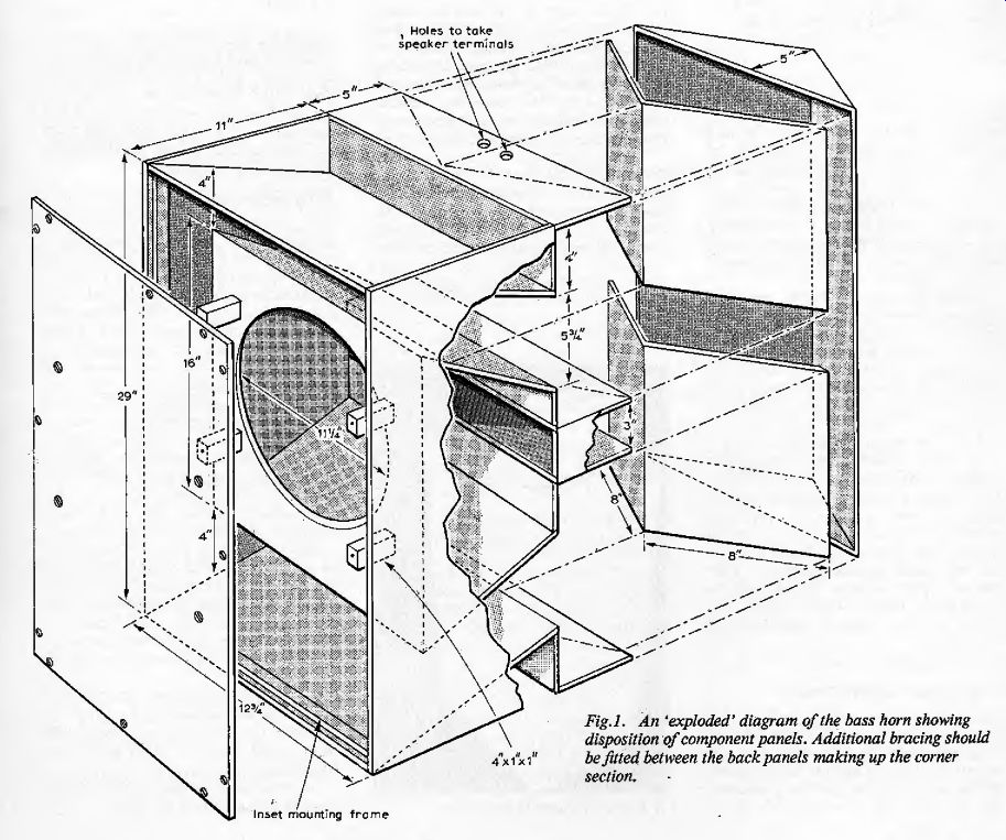
Fig.1. An 'exploded' diagram of the bass horn showing disposition of component
panels. Additional bracing should be fitted between the back panels making
up the corner section.
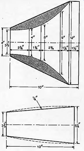
Fig. 2. Details of wood sections used in constructing the treble horn. The
side sections should be cut along the curve shown dotted (see text).
Construction of bass horn
The front, the sloping top and bottom, the back 'corner' panels and the speaker board are mads from 12mm plywood. The front panel is removable. Other wood items can be 9 mm ply. All joints should be made with a p.v.a. adhesive such as Evostik Resin '12'. Structural details are given in Fig. 1. In this version the Baker Major 12 driver is mounted from the front against a strip of rubber which should be fixed on the front of the board round the edge of the 11.25 in diameter hole to provide an air-tight seal. The front panel does not need a seal but the inset 1 X 1 in mounting frame should be firmly glued in place, and will need chamfering in the lop and bottom positions.
Before the triangular corner section is attached, airtight speaker terminals should be fitted, Connecting wire is soldered on and fed through the back-of-cone chamber out through the hole in the speaker board.
The wire should be .soldered to the tags on the drive unit and the drive unit screwed down tightly.
Four 4 in bracing posts, cut from 1 X 1 in wood should be stuck on to the speaker board, round the drive unit, using p.v.a, adhesive. When the joints are dry paint the ends (with poster paint for example) and press the front panel up against them. Remove the panel, mark its top, and drill through at the center of each area of transferred paint. The edges of the front panel should also be drilled, as shown in Fig. 1, and the panel screwed into place.
This completes the bass section.
Construction of treble horn
As in the concrete version the horn has flat top and bottom and curved sides. Fig. 2 gives details for the cutting of the sections. Taking the top and bottom pieces first each piece can be cut from a rectangle 10 X 12 in, and 12mm ply should be used. Each six-sided piece of wood should be marked up as shown and the curves constructed. The areas shown shaded will lie outside the horn when it is finished.
The curved sides of the horn should be cut from a flexible plywood such as bending ply. The cutting should follow the dotted curve so that the side can be glued vertically along one of the curved lines drawn on the top or bottom panel. The joint should be made using an 'impact' adhesive as the wood will be under stress.
The remaining flat panel can be matched up and similarly fixed in place.
Throat section. Cut a 3.5 in diameter hole in a 4in square piece of 5 mm ply (not shown in Fig.2) and glue it in place over the throat end of the horn. Fill the inside of the throat region with Polyfilla (interior grade of course) the four 'fingers' of plaster stopping about 3y in from the throat. This procedure provides the correct exponential transition from circular to rectangular cross-section.
When the Polyfilla is dry give the inside of the horn a layer of undercoat and a couple of layers of gloss paint. The Eagle FR4 drive unit can be fitted to complete the treble horn.
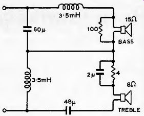
Fig. 3. Crossover circuit using a ^ section series network. Resistors can be jW.
---- A finished speaker in its corner.
Crossover circuit
The modifications to the bass horn have reduced its efficiency. Advantage is taken of this in that the attenuating resistors in series with the FR4 are bypassed with a small capacitor to boost the top and compensate for the somewhat reduced efficiency of the horn at high frequencies.
The series network is shown in Fig, 3.
Winding the chokes. A 2 in piece of 1 in diameter ferrite rod (with cardboard discs glued on at the ends) can be wound with 37 ft Sin of 24 s.w.g. enamelled copper wire. The turns should be close and the layers neat. The ferrite rod is available in 4 in and 6 in lengths from G. W. Smith (Radio) Ltd. To break the rod, first file a shallow notch. Place a pin on a hard surface, such as a metal ruler, and with the notch facing upwards press the ends of the rod downwards with the pin lying exactly below the notch. This should result in a clean break.
Capacitors
The reversible 50V electrolytic capacitors used are available from K.E.F. Electronics Ltd, of Tovil, Maidstone, Kent. 60 uF capacitors are available but the 48 uF required on the treble side is made up from 3x 16 usF units. The prices are 48p per pair for the 16 uF, and 68p per pair for the 60 utF units.
Horn performance
The system described (which was demonstrated at the Audio Fair) will work perfectly if the bass horn is placed in the corner up against the two walls. However, a gap of up to four inches will result in no significant change in performance. The treble horn can be turned round to alter the apparent direction of the sound.
Because very few loudspeakers are capable of launching plane waves at mid-range frequencies few listeners ever hear really good stereo. It is a characteristic of a well-designed radial horn (and a well-designed flat electrostatic radiating element) that the pressure contours have flat fronts. The intersection of two such wavefronts, provided by loudspeakers angled in toward the listener, produces a stable stereophonic image. Constructors of a pair of horns for stereo reproduction will find that they can move freely about in their listening room in the same way that they can move about at a live recital.
Of course, the type of radiation pattern described is a sine qua non for worthwhile quadraphony.
Overall efficiency of the system is such that it is unlikely to be overdriven in domestic use, even at high sound levels, when used with a 10W-per-channel amplifier, A provisional patent application has been filed on aspects of the system.
-----