High-quality design for mains/battery use
For some years the author had contemplated the possibilities for the provision of music of reasonable technical quality, by way of headphones, while away from home on camping holidays --which were normally taken in scenically attractive but physically remote parts of the countryside. Of the available alternatives, the use of previously recorded tape cassettes seemed the most satisfactory, but it is unlikely that further action would have been taken on this matter but for the current availability at an attractive price of good-quality cassette mechanisms made under Staar patents by Garrard and Goldring-Lenco.
It must be explained, at the outset, that the intention was not to provide an instrument which would equal or exceed that of expensive and carefully engineered "transcription" cassette recorders, but rather t" evolve a straightforward and relatively inexpensive circuit arrangement which would nevertheless provide a standard of performance which would be acceptable in the context of existing, high quality, audio equipment. In the event, the performance of the prototype has substantially exceeded expectations, and has led to a major revision of the author's opinion of the performance obtainable from this medium.
In particular, it would appear that, with good system design and appropriate attention paid to recording and bias levels in a direct recording made from a good quality Lp disc onto a reasonable quality ferric-oxide cassette tape, the major component of noise on replay is likely to be the surface noise on the original disc. Also, the differences between the source material and the cassette transcript can be sufficiently small that they are not readily apparent, even on A-B comparison.
Basic circuit
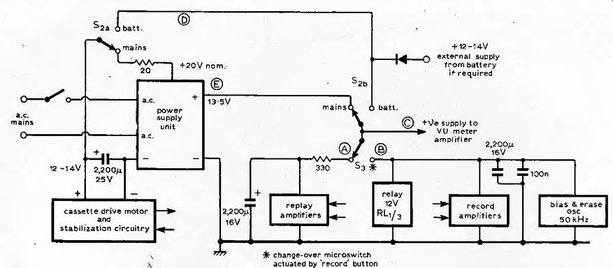
The general layout of the system adopted is shown in Fig, 1, The DC power supply unit has two outputs -- one of about 12-14V at 200-400mA to feed the DC drive motor which operates the cassette feed, and which has its own speed control system incorporated by the manufacturers, in the case of the Garrard CT4 used in the prototype -- and one having a well-smoothed and electronically stabilized output preset to a nominal 13.5V, which feeds either the replay or record amplifiers, Between these two lines there are two changeover switches, to the center point of which can be connected a 12-14V DC supply, so that the system can also be operated from batteries.
The changeover switch in the amplifier supply line is a small microswitch, not supplied with the cassette mechanism but operated by a protruding tag on the side of the record push button on the mechanism. To make a recording, this is depressed--before the cassette is inserted, when a mechanical interlock retains the button in the inward position. When the DC supply is connected to the record amplifier panel, it also energizes a 12V, three-pole change-over relay connected in parallel with it. This relay transfers the connections from the combined replay-record heads from the input to the replay amplifier to the output of the record amplifier. Under normal replay conditions, neither the relay nor the record amplifier panel are energized. The bias/erase oscillator is mounted at the output end of the record amplifier and is supplied with power when this panel is energized. By using separate record and replay amplifiers some additional component cost is incurred, but the internal switching is greatly simplified.
Replay amplifier
Fig. 1. System diagram showing record/replay switching and battery/mains selection.
Motor stabilization circuitry is provided by the makers of the mechanism.
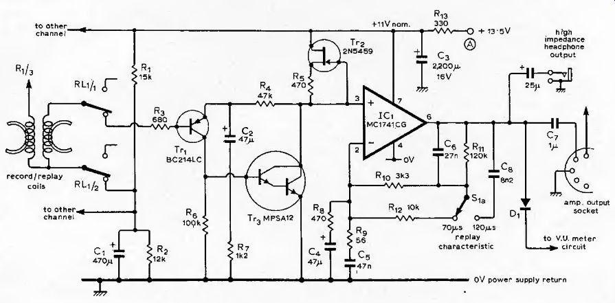
Fig. 2. Relay amplifier.
The use of the extremely low tape speed of the Philips cassette design, coupled with the small head gaps necessary for good high frequency response, and the relatively low coil inductance required for adequate recording and bias current, lead to a very low output voltage from the cassette replay heads. In the stereo configuration this means a 0VU (normal maximum record level) output of some 800-1000uV, and actual signal levels down to a few tens of microvolts. Under these circumstances, it is imperative that great care is taken, both in the design of the input amplifier circuit and in the layout of the wiring from the heads to this, to prevent obtrusive noise or hum. The use of a d.c, tape motor greatly reduces hum originating in the motor, but the mains transformer in the power supply should have a low external mains field and should be as far away as possible from the replay amplifier input wiring and replay heads.
In the prototype, as the mains transformer which had been obtained was not very well designed from the point of its external 50Hz field, a home-made Mumetal shroud was fashioned from a surplus c.r.t. screen to enclose it and this completely solved the problem.
The input circuit of the replay amplifier is shown in Fig. 2; the amplifier is optimized for the minimum practicable noise voltage, to which the major contributory factors are Johnson noise, due to thermal agitation in the input circuit and input device base diffusion impedances (minimized by making the input impedance as low as practicable and by the correct choice of input devices --epitaxial-base silicon bipolar transistors are preferred): "Shot" noise, which is proportional to both current and bandwidth; ¦"excess" or "1/f" noise, due to imperfections in the crystal lattice and proportional to device current and root bandwidth, and inversely proportional to root frequency; collector-base leakage current noise, which is influenced both by working temperature and collector-base voltage; and finally surface recombination noise in the base region. Where these are approximately calculable, the equations shown below are appropriate.
----
Johnson (thermal) noise V= i/4KTRAf
Shot, noise i = \/2qIDC\f
Modulation (J/f) noise vm= '¦f-1
where delta_f is the bandwidth (Hz) K= 1.38 X t the temperature (K), q the electronic charge (1.59X 10^-19 coulombs), f the frequency and R the input impedance.
In practical terms, this means using a silicon bipolar epitaxial-base transistor as the input device, which should be of p-n-p form to take advantage of the better surface recombination noise characteristics of the n-type base material, at an appropriately low collector-to-emitter voltage, say 3 to 4V, with as low a collector current as is permissible and a base circuit impedance giving a suitable compromise between Johnson noise and device noise figure requirements. In the case of the Texas instruments BC214LC, the optimum collector current and base circuit impedances are 10uA and about 800 ohms. This gave, on the prototypes of this amplifier, a measured noise referred to the input of some 0.2uV which is only slightly above the predicted Johnson noise value for the known input impedance and equalized bandwidth. In practice, the input noise introduced by this stage is sufficiently less than that of the tape background for it to be unimportant as a contribution to the overall system noise figure.
In the second stage of this amplifier, where the replay equalization (frequency/amplitude response shaping) is performed, a good-quality integrated operational amplifier "gain block" is employed, as in ail the other gain stages of the system. The unit chosen is the Motorola MC1741CG, which is a fairly standard 741 but in an 8-pin T039 metal-can encapsulation, and is, in the authors experience with these devices, much to be preferred on grounds of reliability. Two equalizing characteristics are provided, having 70uS and 120uS upper time-constants. Of these, the former is the internationally agreed standard for chrome tape, and the latter is the normal standard for ferric types.
The output from this amplifier, about 0.4volts RMS, at 0VU and 660Hz, is taken to the output socket, and the VU meter through an isolating silicon diode. A similar isolating diode on the output of the record amplifier circuit allows the VU meters to be used both on record and replay settings, which is useful for assessing tape output characteristics, and the recording levels of recorded cassettes.
The two replay characteristics are shown in Fig. 3, and are determined by the switched values of R10,12 and C6, 8. Some additional treble lift to compensate for head limitations is given by R9, C5 and gives rise to the part of the curve indicated in Fig. 3.
Although the author has some personal reservations about the use of series feedback configurations in the case of magnetic pick-up input equalization arrangements, where at the upper end of the recorded frequency range it is possible to generate relatively large pickup output voltages with consequent risk of distortion due to common-mode failure, in the case of cassette replay heads the likely output voltages are so small in relation to the input device voltage that this is a negligible problem. Also, to design for the lowest practicable noise level, series feedback configurations remain the simplest form to implement, although in higher-speed, higher-output recorder systems it could be worthwhile to introduce feedback, around an inverting amplifier, at a low impedance at the earthy end of the playback coils.
To avoid replay head magnetization problems due to switch-on current surges through the replay coil windings on the charging of an input series capacitor, the replay coil is connected between the input reference voltage source and the base of the input transistor, so that the total current flow through this is limited to the base current of this device --about 0.1uA. (Head magnetization is less of a problem on record due to the demagnetizing effect of the fairly large bias voltage applied to it during recording. It is, however, important that the time constant of the record output circuit should be shorter than that of the decay of bias voltage, which is ensured by the use of fairly substantial capacitor values on the record amplifier positive supply line.)
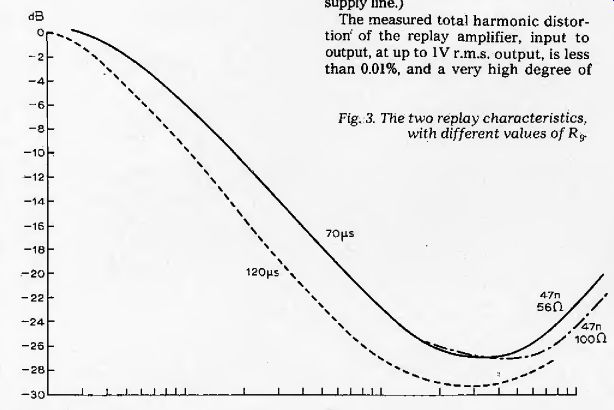
Fig. 3. The two replay characteristics, with different values of R9.
The measured total harmonic distortion' of the replay amplifier, input to output, at up to IV RMS output, is less than 0.01%, and a very high degree of h.t.-line noise and ripple rejection is given by the use of a constant current source load (Tr2) in the first stage.
--------
Measured performance figures of prototype
(Garrard CT4 mechanism)
Frequency response ±1dB 35Hz
-12kHz (BASF LH Super C90)
Channel separation 45dB at 1kHz
Erasure better than 50d6
THD at 0VU (660Hz) 0.75%*
Replay amplifier background noise, CCIR weighted, -56dB.
Zero recorded level background noise, CCIR weighted, -52dB.
Bulk erased tape background level, CCIR weighted, -54dB.
The above figures refer to a 1kHz tone recorded at 0VU on BASF LH Super C90. Both channels are identical to within 1dB, Record amplifier THD at + 3VU less than 0.02%
Re-play amplifier THD at +3VU 0,01% (Residual distortion less than background noise at -6VU.)
This figure should be considered in the context of typical disc replay figures (e.g. 1.2% and 0.6% harmonic distortion for 20cm/s at 1 kHz, vertical and lateral modulation respectively) for a good-quality pick-up cartridge. In a good-quality arm, rather than in comparison with the less than 0.1% THD typical of a good-quality audio amplifier.
--------
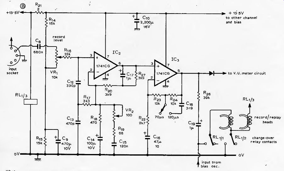
Fig. 4. Recording amplifier.
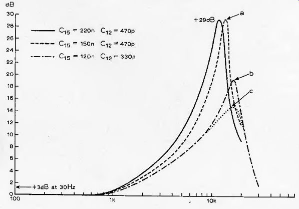
Fig. 5. Recording characteristics with variations in C15 and C12. The peak
heights are adjustable by VR2 (b) being the compromise adjustment and setting
for optimum square wave reproduction.
Record amplifier
Since the design, value of input sensitivity for this amplifier is not very high --50mV RMS input at 1 kHz for a 0VU record level --great care to obtain a high signal-to-noise ratio is unnecessary (the difference in recorded noise obtained by replacing the input MC1741CG with a very low noise circuit such as that used in the replay amplifier is only of the order of 0.75dB). A simple amplifier design based on a pair of these operational amplifiers is therefore entirely adequate, and confers a number of minor advantages in addition to those of simplicity and economy of component cost.
To avoid the necessity for winding coils for the generation of the required peaky record characteristic (desirable to offset shortcomings in the head performance, tape and recording characteristics at the upper end of the recording range) an active RC circuit arrangement is employed. This is shown in the circuit diagram of Fig, 4, and consists of the network R16, R17, C12, C13 in conjunction with R19/VR2 and C15.
The recording characteristics obtainable from this are shown in Fig. 5, for various component values, which may be of use if it is desired to use different record heads to those supplied with the Garrard CT4. The magnitude of the pre-emphasis hump in the 13-15kHz region is determined by the setting of VR2. (a preset component on the Circuit board), while the basic recording treble lift time constants are determined by C12 and C15.
Changeover from the basic 70uS recording characteristic to the 120uS one is by switching C18 into circuit. The new cassette-standard bass pre-emphasis at 3180 uS is provided by C17, R27. A 39k swamping resistor is interposed between the output of the record amplifier and the head, to approximate to a constant-current recording condition. Since the impedance of the head at the upper end of the frequency range of the recorder is less than 10k the loss of HF due to this is small, and readily compensated for in the equalizing circuitry. With this value of output swamp resistor, attenuation of the bias voltage by the low output impedance of the 1741 is sufficient to eliminate the need for any additional bias-trap circuit, while allowing record amplifier circuit outputs of up to +3VU with less than 0.02% THD at 1kHz.
With the recording heads used in the prototype, a 0VU record level at 660Hz, chosen to avoid regions in which pre-emphasis characteristics would influence the result, corresponded to 2.25VRMS at the output of the recording amplifier. Since the output magnetic flux characteristics of the heads were not specified, this level was chosen arbitrarily as the one at which a third-harmonic distortion level of approximately 1% was given at 660Hz on a good quality (BASF Super LH C90) ferric tape. This gives a + 3VU setting of 3.1V RMS, which is below the amplifier clipping level on 13V supply line voltage.
The output of the record amplifier is taken to the VU meter circuit through a silicon diode, but since the record output is higher than that of the replay, an attenuator is included in this circuit to bring the two outputs to equality.
The 47k-Ohm resistor to the zero-volt line serves to provide a forward current to bias the diodes into conduction.
Switching between record and replay in the VU meter circuit is automatic since only the circuit in use has an output above the zero-volt level, the other one being disconnected from the supply line. Unwanted signal transfer through this diode feed network is of a very low order magnitude.
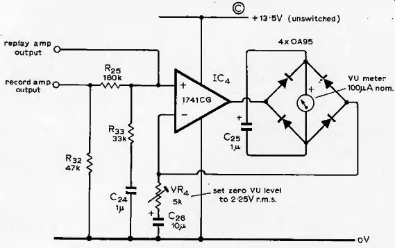
Fig. 6. VU meter circuit
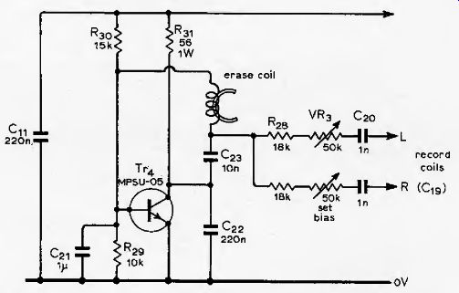
Fig. 7. Erase and bias oscillator, with, continuous variation of bias level
Provision is made on the PCB for the level to be switched.
VU meter
This is a straightforward precision millivoltmeter of conventional type, in which the meter rectifier bridge is connected in the feedback loop of an operational amplifier as shown in Fig. 6.
Although this is a more elaborate arrangement than most conventional VU meter systems, the cost of the operational amplifiers and the associated germanium diode rectifiers is small in comparison with even a modest twin VU meter, and the arrangement has much in its favor in a very linear AC-to-DC conversion, flat frequency/ amplitude response, high input impedance, and short output voltage rise time due to the low output impedance of the amplifier. This latter feature is of particular value in tape recording, where the signal level meter should ideally have zero inertia so that it can follow the modulation of the signal without missing short-duration peak levels.
Bias and erase oscillator
A fairly common and irritating feature of inexpensive cassette recorders is their inability to erase fully an existing program on a tape, when a further recording is being made on top of this.
For satisfactory erasure of ferric and ferrichrome tapes, at least 20V RMS should be supplied to the erase coil, and for chrome tapes a value as high as 25V may be required with typical cassette erase heads. To obtain voltages as high as this with low-voltage lines, it is customary to use a push-pull oscillator driving a step-up transformer, but some care is necessary to avoid harmonic distortion which can impair the recorded signal quality and s/n ratio.
A simpler method, which avoids many complications, is to use the erase head as the coil in a self-oscillating circuit, and employ the Q-multiplication of the tuned circuit around the erase coil both to provide the necessary voltage swing and also to improve the purity of the waveform. The circuit shown in Fig. 7 is a modified Colpitts, and provides an output of 25-33V RMS at the required erase frequency (50kHz), with supply voltages in the range 12-14 volts and with a waveform distortion of less than 1%, even when loaded with the bias circuitry. The current consumption is, however, of the order of 100mA, giving a transistor dissipation of about 0.7W. The Motorola MPS-U05 is particularly suitable, but other high-gain, high-transition-frequency 1W devices are quite suitable since the circuit is not particularly critical of component values or types, except in so far that these may modify the operating frequency, which should be within the range 50kHz ± 5%, The HF bias waveform is also derived from the erase coil, by way of a resistor-capacitor chain, VR3, R2g, C20, to each record head output (VR3 is twin-gang). Since the purity of the bias waveform at the recording head is the design requirement, it is tempting to use a value of series capacitor (C20) which will be series resonant with the record coil at the bias frequency, as is fairly standard commercial practice. However, on reflection, confirmed by measurement, it is better to use a larger value of C20, and take advantage of the integrating characteristics of the series network to attenuate higher order distortion components in the bias waveform, as seen at the head.
The bias voltage required across the record coil is dependent on the tape used but, as a guide, should be in the region 5-7V RMS, with the CT4 heads.
The signal level, for reference, at this point, is only about 50mV.
Garrard Engineering Ltd now tell us that production of the CT4 mechanism is to stop in June. As mentioned in the article, however, Goldring Ltd also market a unit made under the Staar patents and this will continue to be available for some years. The type number is CRV and one difference between the two is that the CRV does not incorporate motor speed stabilization.
Any convenient power supply circuit may be used for a.c. mains operation, provided that it can be set to give a stable, ripple-free output of 13.5-14V at output currents up to 250mA. A suitable design is shown in Fig. 8. The low-value resistor in the record amplifier supply line is to limit the supply line current surge through the changeover microswitch when the large capacitor on this line is connected in parallel with the capacitor on the output of the power supply. To avoid noise originating from the pulsating current demand from the d.c. cassette-drive motor-control circuitry, the recorder supply is taken directly from the power supply reservoir capacitor through a 20 ohm, 10W resistor, with the negative return line being also directly connected to the reservoir capacitor, rather than to a chassis return.
The chassis itself is only connected to the zero-volt line at the input to the replay amplifier.
Recording and bias levels
One of the most obscure areas in the field of tape recording, in the eyes of the layman, is the interaction between tape types and biasing levels. While much information has been published on this subject, it is often discussed in obscure terms which make the argument difficult to comprehend. Since it is possible that the construction of a cassette recorder of this type may be of interest to those with no previous experience in this medium, an attempt has been made to provide a simple introduction to this topic.
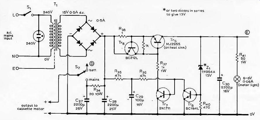
Fig. 8. Power supply. The motor is fed with 3.5V by the stabilizer, but the
solenoid is provided with the full I2-14V.
In general, it is not practicable to obtain an adequate remanent magnetic flux in a magnetic tape, for the reproduction of signal waveforms of low harmonic distortion and good output level, unless a high frequency "bias" of suitable magnitude is superimposed on the signal at the time of recording. The effect upon the various signal parameters of variations in the bias level is shown in schematic form in Fig. 9. From this it will be seen that there is not a single biasing level which is optimum for all recorded frequencies, and that the optimum level for 1kHz is in excess of that which gives the highest output for, say, 10kHz. Also, the level which gives the lowest recorded noise level is less than that which gives the lowest THD.
It is apparent from this that the setting of this parameter is one which demands some compromise, and the one which is chosen will depend upon the preferences of the user. In general, for cassette recorders, the chosen bias is that which gives the maximum output at 330Hz, or a slight excess of that optimum for 1kHz, and the reduction in output at higher frequencies is compensated by modifications to the record pre-emphasis curve. However, the required bias and compensation characteristics will be different from one make of tape to another, and from one design of record/replay head to another. In this design, the decision had been taken, partly in the interests of running costs, and partly in the interests of minimizing wear in the Permalloy heads, to optimize the design for "ferric" tapes rather than chrome types, and the Philips standard low noise C90 was taken as the reference. It was found, however, that the settings derived for this was also optimum for “super" tapes of the types exemplified by Memorex MRX, and BASF Super LH, although these gave an improved performance.
In general, there is very little difference in the background "bulk-erased" noise levels of most good-quality commercial cassette tapes, although there will be larger differences between the noise outputs of tapes passed through a recorder set to record at zero signal level. The greater the degree of homogeneity of the tape oxide layer, the tower the zero-recorded-level noise will be, down to a minimum which depends on the fundamental granularity of the oxide medium. The recently introduced "super" series tapes have a more uniform oxide coating, which can give a 1-2 dB zero-signal background level improvement.
However, there are also improvements which have been made in the output level and harmonic distortion for a given output level, due to a more careful balance of grain shapes and sizes. The extra 2-3 dB in output can lead, in total, to a small though audible improvement in overall signal-to-noise ratio (some typical results are shown in Fig. 11, and Table 1.) Useful though this is, a far greater capacity for improvement in overall performance lies in the hands of the user in a careful choice of the recording level setting. Ideally, one should record at as high a level as possible, so long as few signal peaks significantly exceed the DVU level. A 1-2 dB excess is unlikely to be noticed in replay, especially with good tape, provided that the duration of overrun is brief, and the difference in s/n ratio from "correct" to over-cautious choice of record levels can readily exceed the difference between a cheap tape and an expensive one.
Probably the best way of choosing recording levels is to set the mechanism to Record but with the pause button pushed in, and in this condition to experiment with the gain settings until the optimum setting is found, when the recording can be started. In the case of a live performance, assuming one has the co-operation of the performers, it is usually possible to persuade them to execute a known fortissimo and set the record levels appropriately for this.
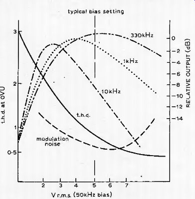
Fig. 9. The effects of changes in the HF bias level on output, THD, and modulation
noise.
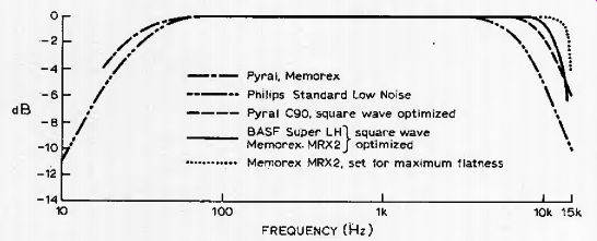
Fig. 10. Record/replay frequency/amplitude curves for a variety of tapes,
optimized for maximum flatness and for best square-wave reproduction
Table 1.

Relative output at 660Hz (0VU recording level)
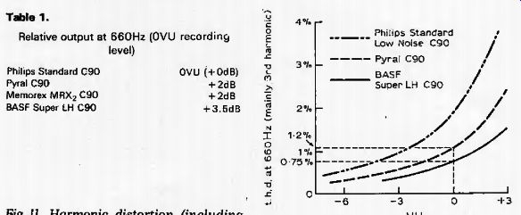
Fig. 11. Harmonic distortion (including noise) as a function of recording
level for three types of tape.
Noise characteristics of the system
During the development of this circuit, the sources of noise in the system were investigated at some length, since, although it was envisaged that some form of external noise-reduction system would be incorporated for use during replay, it seemed advisable to try to minimize noise in the design before taking additional palliative action. The reduction of noise in the replay circuit has already been described; if the unweighted noise level at this stage, without tape, is taken as the unit, the bulk-erased-tape noise level corresponds to about one and a half or two units, and the zero-record-level noise (with the circuit parameters arranged in accordance with normal practice) was then equivalent to some five or six units.
Obviously there was little that could be done about the noise level of the tape, as received, but it seemed that quite a lot could or should be done about the 14dB worsening of this during no-signal recording. Indeed, if it were possible to get down to the level of the original tape, the overall performance would have been beyond reproach, in spite of the low tape speed and narrow tape width. An additional piece of evidence which seemed of interest was that the replayed noise was "whiter" than would have been expected from an original white-noise source (i.e., the tape) when replayed through the type of equalizing characteristic employed in the replay amplifier. This seemed to be a common characteristic of commercial cassette recorders, which all sounded "whiter" on the replay noise tone than seemed reasonable to expect. It was also observed that changes in the level, frequency or shape of the bias waveform made no difference to the result.
The conclusion began to grow that the problem was due to generally-distributed noise, in the source and record amplifier, being selectively amplified in the 10-15 kHz band and applied to the tape at high levels through excessive signal pre-emphasis.
Having become convinced on this point, the attempt was made to determine the optimum compromise between flatness of frequency response and signal-to-noise ratio for a given record level. At this stage it was found that optimization of a recorded 1kHz square wave to reduce the initial overshoot and ringing found when more conventional magnitudes of preemphasis were applied gave also the best performance compromise on bandwidth against s/n ratio. The bias levels found during this exercise were compared to those obtained by more conventional setting-up procedures, and found to be substantially identical.
However, the zero-signal-level recorded noise was found to have been reduced by about 10dB by the process of square-wave optimizing, as compared to that given by frequency response optimizing. The two curves are shown in Fig. 10, and it will be seen that the HF loss amounts to only 1dB at 10kHz and some 4dB at I4kHz, which can be remedied by the use of amplifier tone controls on replay with very little detriment to performance.
The final conclusion is that in general far more HF pre-emphasis is employed on recording, in the interests of maximum flatness of the published response curves, than is sensible in the light of the overall performance, and that with more prudence exercised in this respect, noticeable improvements could well be made. Interestingly, program recordings made before and after optimizing of the square-wave performance of the recorder did not show the expected small loss of higher frequencies, with the upper register seeming both cleaner and more extended than before, possibly due to the lessening of the incidence of HF, tape or head saturation.
One final recommendation in this respect is that for one's own use, even on ferric tapes, the 70 uS characteristic should be used both on record and replay. However, this is a choice which can be assessed readily by individual experiment. Certainly, in the case of the author's prototype, the use of this equalizing time-constant, in association with an optimized square-wave characteristic, has given a system in which the tape noise, on a good quality tape, is sufficiently unobtrusive to render further noise reducing circuitry unnecessary.
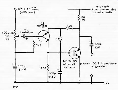
Fig. 12. Class A headphone amplifier, with a gain of 5.
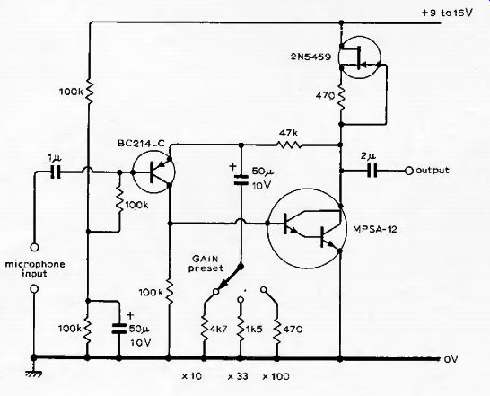
Fig. 13. Low-noise microphone pre-amplifier.
Bias and equalization settings
It will be apparent from Fig. 9 that adjustment of the HF bias level of the recorder will have the effect of altering the whole response curve, by altering the effective recorded levels of the HF and IF components relative to one another, and it may therefore appear difficult to optimize either the bias or the equalization. The suggested method is therefore as follows:
---Set VR2 so that the response curve on record is as curve A on Fig. 5., (approx. 85 ohm) when measured at the output of IC3.
---Set the bias level so that there is approximately a 1-2dB drop in output at 1kHz.
---Record a square wave at 660Hz, and make small adjustments to VR;, until the cleanest leading edge is obtained on the replayed square wave, with only a small single overshoot.
---Finally, leaving VR2 set at the chosen value, record a 660Hz square-wave at various bias levels and adopt the one which gives the best overall squarewave shape for the tape which it is desired to employ.
The technique of square-wave optimization is well known in the audio field as a means for setting tone-controls and filters to optimum flatness, because of the facility which it offers for a simultaneous examination of a wide range of frequencies. On exactly the same score it would appear to be an excellent method of optimizing bias levels.
While it is hoped that the performance given by the prototype will prove to be fairly typical of the results given by other models built to this design, it is appreciated that in a system in which not only will components vary in types and tolerances, but also the tape transport mechanism and heads (which may be changed during the manufacturer's production run for reasons of commercial availability) may differ from those used by the author, the scope for variability is considerable.
Also, from personal experience, and measurements, there is a considerable variation in performance from one tape type to another, although the consistency of performance of the better-grade tapes from the better manufacturers appears to be fairly good. On the credit side may be set the fact that one does not have quality control problems in a unit that is one-off, and that one can optimize one's channel balance and hi. performance for the tapes one prefers and the heads one happens to possess.
Headphone operation
Both the output level and the drive capability of the final 741s of the replay amplifier are adequate to give a satisfactory signal strength and quality into the 2k-Ohm load impedance of the author's headphones (Sennheiser HD414), so, for simplicity, this was the course adopted.
However, for those with lower-impedance or less-sensitive headphones, a suitable circuit is shown in Fig. 12. This operates in class A, and is suitable for load impedances down to 100 ohms.
Direct microphone recording
The sensitivity of the record input is only intended to be sufficient for recording from an existing audio amplifier or radio tuner capable of delivering some 50-100mV output at a fairly low impedance, and it would not be suitable for microphone inputs. For this purpose a pre-amplifier can be used, of which a suitable circuit is shown in Fig, 13. Three preset gain positions are given, of 10, 33 and 100 x, which should cope with the bulk of microphones likely to be found in practice. A typical gain suitable for a low-output cardioid capacitor electret microphone is of the order of 33, for a normal recording level at half-gain setting on the recorder.
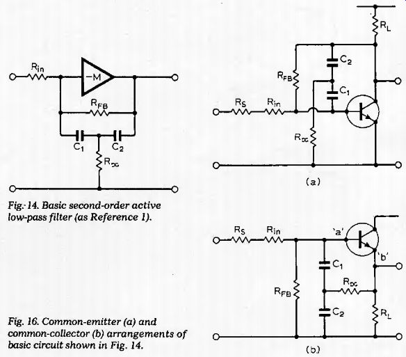
Fig. 14. Basic second-order active low-pass filter (as reference 1).
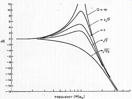
Fig. 15. Frequency/gain response of filter in Fig. 14.

Fig. 16. Common-emitter (a) and common-collector (b) arrangements of basic
circuit shown in Fig. 14.
Appendix
Derivation of record equalization characteristics.
The generation of a recording pre-emphasis characteristic of the general form shown in Fig. 5 is normally done by incorporating a damped LC parallel resonant circuit in the feedback loop of an inverting amplifier stage. However, since it was desired, in the interests of simplicity, to avoid the use of inductors, and it was also required to avoid possible trouble due to the intrusion of 38kHz signals from multiplex stereo decoders, the decision was made to use the gain/frequency characteristics of an under-damped second-order active low-pass filter, such as that shown in Fig. 14.
Fig. 17. Use of the active filter in a stage possessing gain, as in Fig. 4.
This is one of the classic forms of active element, and was analyzed by Girling and Good [1] in the first part of their survey of active filters in Wireless World It has a gain/frequency response of the type shown in equation (1) and illustrated in Fig. 15 for various values
of
Q {l'«)
v v out 1 -f jotV Mn CD / CO Ju --"c H
(1)
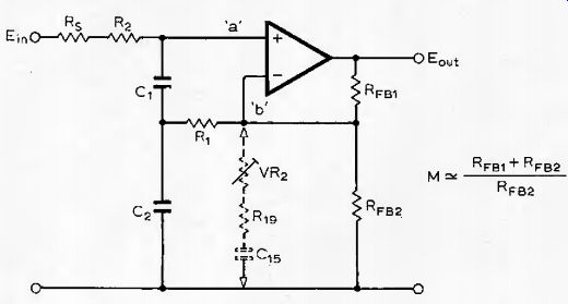
Fig. 17. Use of the active filter in a stage possessing gain, as in Fig. 4.
If this is redrawn, ignoring biasing, in the form in which the amplifying element is a single, common-emitter-connected transistor, as shown in Fig. 16(a), it will clearly be seen that this can be rearranged into the common-collector form of Fig. 16(b) without significant alteration of the expression for the frequency response. (It was pointed out by Girling and Good that a similar rearrangement leads to the evolution of the filter circuit due to Sallen and Key2 from the type based on a feedback loop containing an integrator and a lag, described earlier by Baxandall 3 .) Filters of the type shown in Fig. 14, and 16(b) were used in the authors "Modular preamplifier" design (Wireless World July 1969) and the subsequent postscript to this and the earlier class A amplifier, published in December 1970. The performance of the circuit shown in Fig. 16(b) referred to as a bootstrap or "H" filter, was analyzed by the author in another place 4 and, in a different context, by Hemingway. The operation of the filter circuit of Fig, 16(b), like that of the Sallen and Key configuration, can be realised by any active element in which there is approximately unity gain between points "a" and "b". This allows the use, for example, of a voltage-follower operational amplifier as the active circuit element, or even a non-inverting operational amplifier having more than unity gain, as shown in Fig. 17, provided that an adequate fed-back gain margin is available at the frequency of interest.
The gain and frequency of maximum response of such a circuit is given by equations (3) and (4) where M is the normal gain of the stage with feedback.
1 fc:
' 2vV[C,C,R,(R2+F (3)
c,c2
While, basically, the Q of the system is determined by the ratios of R1: R2+ Rs, in a stage with a shunt network, such as that of VR2,R19 and 0,5 in Fig. 4, the gain will change in the frequency region of the filter attenuation band. The associated phase shift due to this network also modifies the Q and allows adjustment of this by VR2, which is a feature of some practical convenience.
References
1. Girling. F. E. J., and Good. E. F., Wireless World, vol. 75, No. 1406. pp 348-352.
2. Sallen. R. P., and Key, E. L., Trans. IRE., vol. 2. No. L, pp. 74-85.
3. Baxandall. P. J., Wireless World, vol. 61., No. 1., pp. 8-14.
4. Linsley Hood. J. L., Hi-Fi News and Record Review, vol. 18. No. 2., pp. 293-294.
5. Hemingway, T.'K., Electronic Designers Handbook, pp. 283-288.
Component supplies
Goldring-Lenco CRV cassette mechanisms can be obtained from Go Wring Ltd, 10 Bayford St, Hackney, London E8 3SE, or Hart Electronics, Penylan Mill, Oswestry, Salop.
VU meters are available from J. E. T. Electronics, 90a Mawney Road, Romford, Essex.
Motor control and further notes
by J. L. Linsley Hood
In response to one or two queries, the following notes are offered. Several cassette decks have now been completed, using alternative designs of printed board, and have proved very successful.
Motor control
Circuitry for the control of the drive motor and solenoid is shown in Fig. 20. It is required to supply or withhold current from the cassette-retaining solenoid and to supply a constant drive to the motor in the presence of supply variations.
Solenoid control. Tr3 normally conducts and energizes the solenoid. As the motor turns, the pulse-generating switch in the mechanism (yellow and green leads in the Goldring deck) keeps Tr1 conducting, which cuts off Tr2 and allows current to flow through the solenoid and Tr3. When the motor stops, so does the switch: Tr1 ceases to conduct and, after 3 seconds (C2R5) Tr2 conducts, cutting off Tr3 and de-energizing the solenoid. The cassette is thereby released. If the "pause" contacts are made, the motor stops, but the cassette is retained in position.
Speed control. The motor is supplied with constant current via Tr5, Tr4 is conducting. Back e.m.f. developed by the motor beginning to turn is applied to Tr4 emitter, reducing its forward bias.
This reduces the current into Tr5 base and tends to reduce the motor speed --the effect is to stabilize the motor. Tr5 behaves as a constant-current source by virtue of the feedback from its collector to Tr4 base.
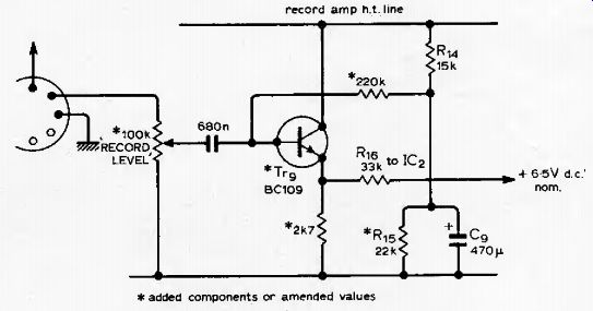
Fig. 19. Buffer amplifier to match a DIN source to the recording amplifier.
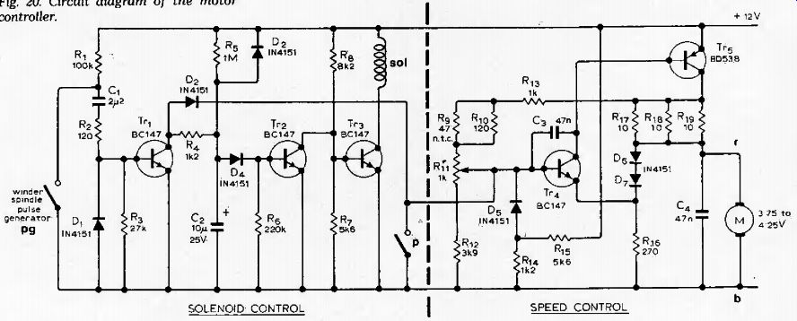
Fig. 20. Circuit diagram of the motor controller.
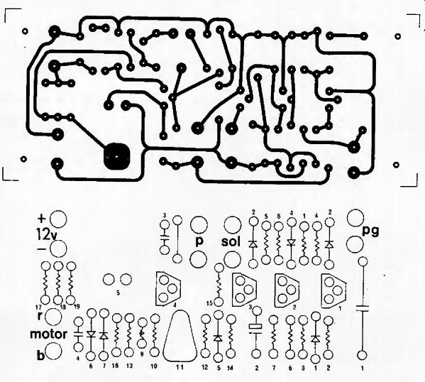
Fig. 21. A suggested, actual-size layout for the controller. The layout and
modifications to the speed control circuit are due to Mr A. H. Milligan.
Record input impedance
There are, unfortunately, two conventions on the impedance levels employed for signal handling prior to tape recording. Of these, the older, and I think the more sensible, is the "600 ohms, 0 VU" (+0 to -60dB, ref, 0.77 V RMS), system which seems to be used by many recording studios, and gives a signal level which can be handled comfortably without problems of degradation due to noise. The other, and the one which is being used increasingly in commercial amplifier "recorder" outputs, is the DIN standard, which implies basically a constant-current source, developing a nominal 1mV RMS for each 1kOhm of recorder input impedance. Predictably, this leads to a degradation of signal quality due to thermal noise unless fairly high value input impedance circuits are employed.
The convention for which the recorder described above was designed was the 600-ohm source impedance one although, taken in general terms, this means any range of source impedances in the range zero to a few kilohms, and the system as it stands would probably have inadequate gain if operated from a DIN source. It is, however, not practicable simply to increase the input record level potentiometer to 50k or 100kOhm since the source impedance of IC2 influences the Q of the HF pre-emphasis system (see Appendix), While the effect of the existing 10k potentiometer, when driven from a fairly low source impedance, is negligible, this would not be true for a higher value DIN input, If, therefore, this is to be used with a commercial unit having this convention (as distinct from a home-constructed item, in which it is probably most convenient to take the recorder feed at the pre-amp output, in parallel with the power amplifier input), it is recommended that a small buffer circuit should be attached to the output of the record level potentiometer, as shown in Fig. 19.
Replay HF stability
Proximity of output and input leads may cause instability in the replay amplifier. If this cannot be avoided due to layout constraints, a small capacitor (330pF or so) can be connected across the replay output relay terminals (RL1/1, RL1/2) --across the replay coil output in the replay position --without any adverse effect on the HF performance.
Letters to the Editor
LOW NOISE CASSETTE DECK
We should like to take the eminent Mr J. Linsley Hood to task for advising the use of the 70 uS equalization characteristic for use with normal low-noise ferric cassettes. This is most misleading because one of the most serious problems with these cassettes is their lack of response to high-level, high-frequency signals; the 120uS post-emphasis was adopted to try to alleviate this. Even this results in a fully-saturated recorded level of about 10dB below Dolby level at 10kHz. Adopting the 70us equalization characteristic reduces the HF overload figure by almost another 5dB which makes an already bad situation intolerable. This would produce severe HF intermodulation distortion when recording typical musical material at "normal" mid-band modulation levels.
The reason that the 70 uS equalization is adopted for chrome cassettes is simply that they are much less susceptible to HF overload because of the smaller particle size and higher coercivity of the oxide formulation.
We would, however, endorse Mr. Linsley Hood's suggestions for optimizing bias and equalization settings. In our opinion too many manufacturers align their machines to attain the ultimate in frequency response (or "specmanship") to the detriment of other aspects of the reproduced quality.
One notable exception to this is the British manufacturer NEAL, who quite deliberately align their machines to be -2dB down at 12kHz on ferric tapes.
This compromise produces a similar result to that obtained using Mr. Linsley Hood's square wave technique.
C. J. Evans, J. Dawson, A&R, Cambridge.
The author replies:
The original Philips recommendation for the equalization of the "Musicassette" was for time constants of 1590 and 120 uS, of which the first was to compensate for anticipated inadequacies in the IF response and hum pick-up problems with the circuitry, and the second was to remedy the known shortcomings of recording head and tape characteristics. Improvements in system design have led to the universal adoption of the 3180 us low-frequency equalization time constant, to bring the cassette system into line with other reel to reel, recording systems, and the advent of chromium dioxide cassette tapes has prompted the adoption of a 70 uS HF time-constant in order to secure some of the advantages which these improved tape types can offer.
As a consequence of this, most modern cassette recorders will offer a choice of HF time constants, whose use is at the discretion of the user, when he is making recordings for himself.
However, the design of recording heads and cassette tape materials has not stood still in the intervening years, and it is my belief that there are many ferric tapes which will give an improved signal to noise ratio, without any significant penalty in terms of HF overload on typical program material when used with the "chrome" 70 uS equalizing time constant, and it was this belief, based on a quite substantial number of tests, which led me to make the recommendation to which Mr Evans and Mr Dawson object.
A shrewd friend once observed to me that rules were made for the guidance of the wise, and the blind obedience of fools, so, in this context I would urge, even in the light of hind-sight, which is said to be an exact science, that users try out the available options, and judge the issue for themselves.
--J. L. Hood