1--An introduction to the Dolby noise reduction system
This noise-reducer design is intended mainly for hiss reduction in magnetic-tape recording machines. The unit can be switched to decode commercially available Dolby B-encoded cassette tapes, Dolby B-encoded FM radio transmissions (as in the USA), or to encode blank tapes from any source. As an alternative, it can be used in trading some of the noise improvement for reduced distortion at peak recorded levels. The Wireless World processor can be aligned without any additional test instruments, the circuit board being arranged to provide the necessary alignment and calibration tones. This article gives background to the 8 system and to the functioning of the noise reducer and subsequent articles describe construction, alignment and calibration of the unit.
In audio systems dynamic range can he defined as the ratio of the largest to the smallest program signal. Dynamic range is typically limited at the high-level end by tape saturation or amplifier signal handling problems: there is usually a fairly well-defined level beyond which compression occurs and distortion rises at a rapid rate. At the other extreme there is a limit on the lowest signal that can be handled, set typically by the noise level of electronic circuits, tape noise, surface noise on discs, or granularity on optical soundtracks.
In concerts, dynamic range can be as high as 90 to 100dB, but once such program material has been recorded, dynamic range is reduced to 60 or 70dB. (When broadcast the range can be as low as 20 to 40dB.) In this situation there are three options-lose that part of the program below noise level, distort the peaks, or distort the range by compression either manually or automatically.
None of these options is altogether acceptable in itself, all distort the original in some way. What is needed is a way of getting round this limitation of dynamic range without the distortion of overmodulation, without losing program in noise and without distortion of range. Before discussing various techniques that have been proposed and tried, we will be more specific about what is required.
As well as not introducing any perceptible non-linear or dynamic range distortion of both steady-state and transient signals, any proposed technique for high quality use should not perceptibly alter the signal in respect of frequency response and transient response. Any signal processors must be able to operate to the normal constraints of audio channels, i.e. operation should not depend on freedom from phase and amplitude versus frequency errors or changes, nor on a linear phase-frequency response; channel overload characteristics should not be worsened. In addition to compatibility with transmission channels, there must be compatibility between processors to the extent that recordings can be interchanged. In reducing perceptibility of noise, there should be no noticeable noise modulation effect and ideally all noises should be reduced by a similar amount, otherwise reducing one kind might unmask another.
Noise-reducing techniques
"Static" methods. The most well-established methods of avoiding the constraints imposed by high noise levels are "static" ones. Examples are the high-frequency pre-emphasis, and subsequent de-emphasis, applied to FM broadcasts and gramophone records and the low-frequency preemphasis used in tapes. They are static because the amount of emphasis given is fixed and does not take account of the signal in any way. At some frequencies, there is thus an intrusion into the possible range of levels that signals can occupy which may mean that some lower than normal limit must be placed on the program level.
Single-ended methods. An alternative approach is the dynamic one of altering the level of a signal by an amount that depends on the signal level, at either the sending/recording end or at the listening end. In examining such dynamic techniques it is expedient to look at the possibilities from a steady-state signal level point of view, with the thinking that frequency and time-dependent variations can be seen as special categories within a level classification. In practice, however, the success of each kind will undoubtedly depend on how well complicated time-varying multi-frequency signal patterns are responded to by the processing circuitry; and to whatever psychoacoustic, or perceptual, effects such as auditory masking, can be discovered and made use of.
The simplest kind of device, within our terms of reference, is the low-level noise gate, depicted graphically in Fig. 1(a), which eliminates signals below a certain threshold level. More useful is a stepped noise gate, where signals and noise below a certain threshold are attenuated by a finite amount rather than an infinite amount-Fig. 1(b), There are a host of variants on this theme. Fig. 1(d) showing another possibility.
A number of commercially-available expanders have used the general approach of Fig. 1(b), including H. H. Scott's "dynamic noise suppressor" and R. Burwen's "dynamic noise filter", operating only at low and high frequencies and with a passband that varies according to signal level. The Philips "dynamic noise limiter" is another example, though its operation is restricted to high frequencies. With these devices, the bandwidth restriction at low signal levels must Inevitably cause some loss of program. Further, any reduction of noise level that can be achieved is likely to be modulated by intermittent mid-frequency signal components, giving rise to what is called breathing. Because they are "single-ended" these techniques must result in a distortion of dynamic range. Thus you can either have the original dynamic range plus non-reduced noise, or a distorted dynamic range and loss of some low-level information with a reduced noise level-but not both at the same time.
Besides altering the level of low amplitude signals, a similar expansion can be achieved by expanding high-amplitude signals. Fig. 2(c), but as well as exhibiting the two major disadvantages already mentioned, this would suffer a third. By having a variable-gain element operating at a high level there are obviously greater risks of generating intrusive unwanted signals as a result of overshooting, high non-linear distortion and a high circuit noise level.
Dynamic processing is often carried out prior to recording or transmission.
The low-level compression characteristics of Figs. 1(c) and (e) and the high-level characteristic of Figs. 2(a) and (b) both enable average signal level to be increased relative to the noise level. But in themselves they suffer from the same disadvantage as do the expanders. Clearly, single-ended methods are inappropriate to normal high quality reproducing systems.
Complementary methods. The only way of avoiding the difficulty of alteration to dynamic range is by the complementary method-the dynamic equivalent of static "equalization". In complementary systems, signal processing before transmission and recording, normally compression, is followed by an equal degree of complementary processing, normally expansion, prior to audition so that the original dynamic range is restored. Noise added by the medium after compression is reduced by the degree of expansion used. In the expander of Fig. [(b) the complementary compressor characteristic would be (c) and the complement of (d) would be (e). Likewise, the transfer characteristics of Figs. 2(b) and (c) form another compander system.
Another kind of diagram makes it easier to visualize what happens so far as levels are concerned. Fig. 3(a) is a typified high-level compander characteristic, showing both the compression and expansion curves. Its equivalent level diagram of Fig. 3(b) shows the reduced dynamic range (indicated by arrows) where the maximum level to be handled by the interposing medium is assumed to be the same--the region marked "overload margin" giving an increased margin against overload and thus lower distortion. Fig, 3(a) shows the same reduced dynamic range produced by the characteristic of Fig. 3(a), but with the intermediate gain shifted so that the low signal levels can be increased in relation to the noise level.
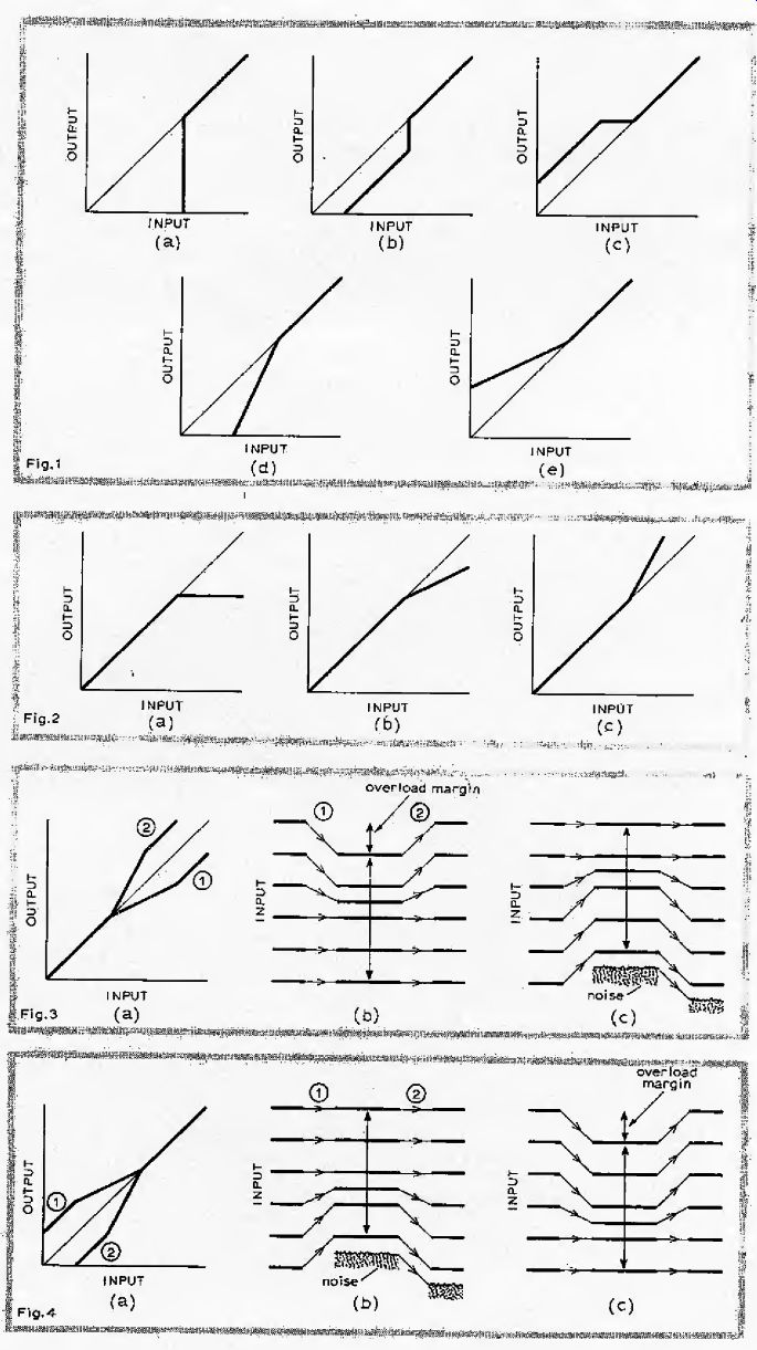
Fig. 1. Low-level noise gate (a) simply loses both noise and signal below
a certain threshold level. Finite attenuation of low-level signals is achieved
with the expansion transfer characteristics of (b) and (d). Such "single-ended" expanders
reduce noise at the expense of distorting dynamic range. Compressors at the
signal source end can raise low level signal above noise levels, but similarly
distort range (c) and (e).
Fig. 2. High-level limiter and compressors (a) and (b) and expanders (c) suffer an additional disadvantage because of processing at a level where distortions would be more obvious.
Fig. 3. Complementary high-level system (a) is able to reproduce original dynamic range while either reducing maximum level to give more overload margin (b), reducing noise (c), or giving a combination of both.
Fig. 4. Low-level complementary system (a) has the advantage that any distortion products are at a low level where they are less likely to be audible.
Fig. 4(a) shows low-level compander characteristics, with the level diagram of Fig. 4(b) illustrating the use of the compressed dynamic range to bring up the low-level signals relative to the noise.
Fig, 4(c) shows how, by reducing the levels by a constant amount, increased overload margin can be obtained. (Notice the similarity between Figs. 3(b) and 4(c) and between Figs. 3(c) and 4(b), the difference being the siting of the region of "linear" operation at either a high level or a low level. Despite the immediate visual contrast between Figs. 3(a) and 4(a) there is clearly a close resemblance between curves 1.) In practice the characteristic curves do not have the discontinuities shown, corners being rounded to prevent objectionable noise modulation. The curves should be capable of easy realization, be readily reproducible and the two complementary curves must be matched to within the required tolerance.
Two recently-introduced studio companders use the general approach of Fig. 2(b) and (c), but with a threshold that is much lower than indicated. The dbx Inc. compander uses a square-law curve above a certain threshold (-60dBm), which in logarithmic terms is a 2:1 compression ratio. The Burwen "noise eliminator" uses a cubic Saw (logarithmically, a 3:1 compression ratio) above a certain threshold. (A fixed HF, preemphasis and a level-independent bandwidth are also features of these systems.) In general, such high level companding techniques suffer from a number of drawbacks: poor tracking between the two processors, high sensitivity to errors in gain in-between processors, overshooting and a risk of overmodulation, both of which could lead to compression in the transmission medium that would go uncorrected on expansion, noise modulation by signals, modulation-product formation as a result of rapid gain changes, all of which are undesirable in a high quality link. High level companders can be very useful however in telephone circuits for example and the Post Office's Lincompex scheme is an example of a compander in which dynamic range is reduced to zero. (Subsequent expansion would not be possible were it not for the fact that information on signal amplitudes is contained in separate pilot or control channel.) The low-level method (Fig. 4) has a high tolerance of channel gain errors, produces modulation distortion at low signal levels rather than high levels, and there is less risk of overloading the medium. It seems a good idea anyway because one might expect the ear to be less sensitive to low-amplitude effects than to the same effects at high level. This then is the basic companding technique chosen for the Dolby system.
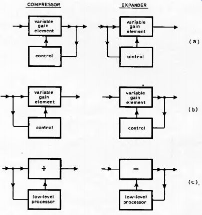
Fig. 5. Conventional companders use the equivalent complementary systems of
(a) or (b) whereas the Dolby system (A and B) uses an additive to method (c)
enabling processing circuitry to be separated from the main signal path.
------------
---
In most electronic signal processing systems there is usually some maximum level beyond which the signal must not be allowed to go and to which levels are frequently referred. Transfer characteristics are therefore usually given in the quadrant shown in which the point of reference is made to be some arbitrary maximum level, rather than the zero signal level of Figs. 1 to 4. (A zero at the axes intersection would represent 0dB and not an origin as in Cartesian coordinates.) In practice such curves are not discontinuous but are smoothly connected to prevent unwanted modulation and to permit easy realization and matching.
------ ------
Dolby low-level compander
In conventional companding systems there are two equivalent ways of achieving compression and expansion. One is to derive a control signal, after subjecting the input signal to a variable-gain element (compressor); expansion or "decoding" would then be achieved by the converse process-the control signal being derived prior to a variable-gain element (expander), Fig. 5(a). The equivalent, alternative, way is to derive the control in the compressor part before the variable-gain element and to subsequently expand by using a control obtained after the variable-gain device. Fig. 5(b). (The first-mentioned method is used in the dbx and Burwen high-level companders.
The Dolby technique makes use of a different approach-with an important difference; compression is achieved by deriving a special low-level signal that is added to the main signal, and expansion is obtained by subtracting a low-level signal from the main one, Fig. 5(c). (Within the low-level processor block, compression is achieved with method (a),)
Of course, the required compander characteristics could have been derived in the normal way, i.e. by direct action of a compressing circuit on the main signal path Figs. 5(a) and (b); but in the low-level approach the whole range need not be subjected to processing. It is obviously in the interests of quality that low-level signals be processed separately, leaving the main signal to a linear path whose quality is not restricted by that of the variable-gain path.
Tracking at high levels becomes easier using this low-level approach, and a tracking error due to channel gain variation would occur at an unobtrusively low level. Additionally with this technique, it is found that sufficiently accurate tracking can be maintained using a control derived from peak and average signal values. Thus the elaboration of an RMS-derived control, which would strictly be necessary for channels having a non-linear phase-frequency response, is avoided.
Notice that in the subtractive part of Fig. 5(c), a negative feedback loop is effectively formed in the low-level "contribution" to the main path. Advantage of this is taken in the Dolby system in that an identical network to that used to produce the additive low-level signal at the encoder, can be used in forming the subtractive component at the decoder, merely by inserting the network in the negative feedback loop of a main path amplifier.
Among other things this means a single processor can be used for both encode and decode functions by a suitable switching arrangement.
In a wideband compander of this kind having the kind of characteristic at Fig. 4, a low-amplitude signal below the operating threshold would result in the maximum amount of low-level boost being applied, and on decoding the noise level will be appropriately reduced; a high-amplitude signal would result in no noise reduction.
Thus an intermittent high-amplitude signal could modulate the noise level, producing breathing (unless high-level signals were present in the same frequency band as the noise. This breathing can occur in any kind of wideband compander, of course). In the Dolby A system this effect is overcome by splitting the audio band into sections in the additive signal path, each section having its own compression and control circuitry. A high-amplitude signal in one band will not then prevent noise reduction being obtained in bands above and below. Within each band, the presence of a high-amplitude signal is relied on to mask, that is reduce the perceptibility of, noise components close to that signal.
Studies of auditory masking show a shift in the hearing threshold In the presence of a (masking) tone, which effect can extend upward in frequency to a considerable extent; downward to a much lesser extent, the amount depending on the level of the masking tone.
When the economics of band splitting are judged against the extent of this masking effect, the amount of noise reduction required, and the value of threshold level In relation to the benefits of the additive technique, it turns out that four bands give a satisfactory compromise of cost versus performance. Splitting the band with 12dB per octave filters in the ranges 80Hz low pass, 80Hz to 3kHz band pass, 3 to 9kHz band pass, and 9kHz high pass would give a uniform 10dB boost (and hence noise reduction) to low-level signals, as determined by setting compression threshold at 40dB below peak operating level. By making the 3 to 9kHz bandpass filter into a highpass filter, an additional boost is obtained, gradually increasing from about 5 kHz to a maximum at 15kHz. The lowest band provides reduction in the hum and rumble range, the second reduces mainly broadband noise, tape print-through and crosstalk, while the upper bands reduce hiss.
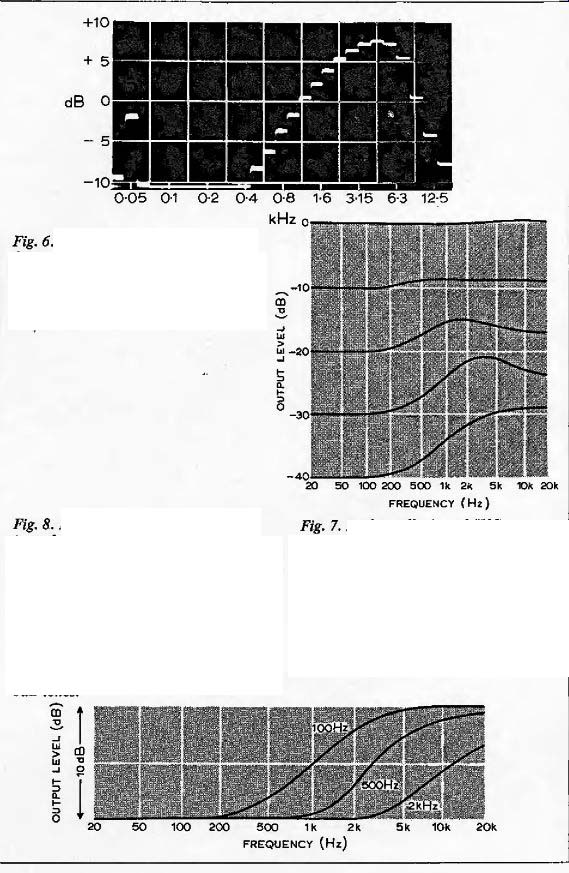
Fig. 6. Noise spectrum of low-noise ferric oxide cassette
tape shows problem is a mid-to high-frequency one, rather than a broadband
one for which the Dolby A system was developed. Fig. 7. In
the Dolby B and JVC a.n.r.s. systems, low-level high-frequency signals are
boosted during encoding by 10dB at low levels, the amount of boost decreasing
as input level increases. Characteristics shown are amplitude-frequency response
curves, with input level as a parameter, for the encoding process. Fig.
8. Because the compressor circuit is made frequency
sensitive in B-type processors, frequency at which boost, and hence noise
reduction, occurs rises with increasing input level. Thus noise reduction
is preserved in the presence of mid frequency signals at high amplitude,
which would otherwise reduce or prevent noise reduction. Curves show response
below threshold level in presence of 0 dB tones.
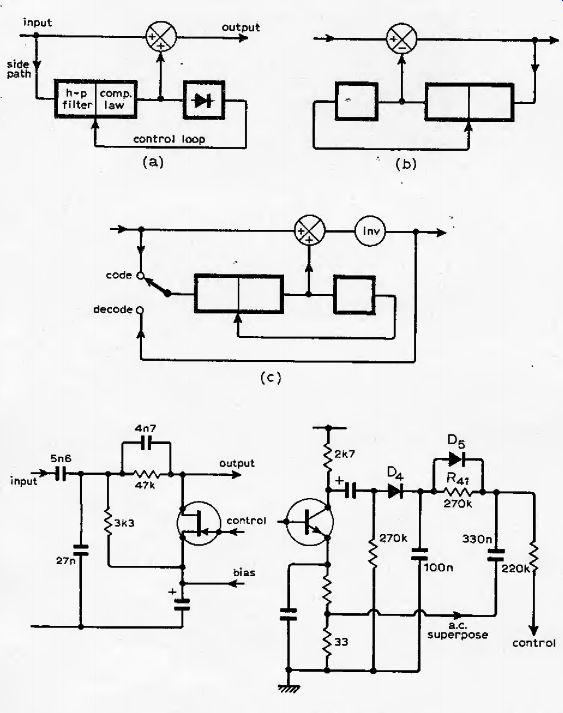
Fig. 9. Characteristics of Fig. 8 are realized by a voltage-controlled filter and compressor which adds up to 10dB of subsidiary signal to the main path during encoding (a). In decoding, a similar network is used to subtract from the main path (b), the network forming part of a negative feedback loop. This loop means that identical networks can be used for encoding and decoding. By placing the phase inversion in the main signal path, as shown (c), it can be left permanently in-circuit, simplifying encode-decode switching.

Fig. 10. Output of high-pass filter decreases after the compression threshold,
set by gate bias, has been exceeded by the control signal. Response curve of
combined fixed and variable filter sharpens when the two turnover frequencies
coincide.

Fig. 11. Control-loop integrator has variable attack and decay times depending
on speed and amplitude of signal changes.
Large transients cause Ds to conduct, shortening loop response time. Superposition of a.c. signal on control loop is to allow FET to operate symmetrically, thus keeping second harmonic distortion to a low level.
Dolby B type system
The cost and complexity of the A system is not really appropriate to consumer products. Moreover, in slow-speed tape machines in particular the noise spectrum has a different distribution to that occurring in the studio situation, on account of the slower tape speed and thin oxide layers used in tape cassettes. Fig. 6 gives a typical DIN-weighted noise spectrum taken from a low-noise ferric oxide tape cassette, showing the noise problem is mainly a mid-to high-frequency one. Noise reduction in the B-type system is therefore limited to this frequency range and Fig. 7 shows the amount of boost (hence noise reduction) applied at various input levels; a fixed high-pass filter placed in the subsidiary signal path would achieve this end. What, then, about noise modulation which in the A system was reduced to imperceptible amounts by the multiband feature? In the B system, such a filter prevents high-level low-frequency tones from activating the compression circuit, so there is no noise modulation by IF components. But there could still be modulation by high-level signals close in frequency to the filter cut-off. The trick to avoid this, unique to the Dolby B circuit, is to move the filter passband higher in frequency, so that the high-level signal would then be below the filter passband, The curves of Fig. 8 show the effect of the variable-frequency filter under the influence of a high-level tone at three different frequencies; the lowest-frequency curve representing the lower limit of the combined filter's translation in frequency. As the figure shows, with a high-amplitude tone of 500Hz applied, there is some 8 or 9dB of noise reduction at 10kHz; even with a tone at 2kHz there is still some noise reduction obtained.
Had the filter passband remained fixed, these high-level tones would have caused the variable-gain element to operate, resulting in reduced or zero contribution from the subsidiary path, and hence little or no noise reduction.
Fig. 9 shows a simplified block diagram of B-type processors, the encoder at (a), and the decoder at (b) with the same filter and compressor circuitry now in a negative feedback loop. In (b) a phase inversion is clearly required, which in (a) it is not.
A simple dodge, that leads to a simplified encode/decode switching arrangement, is to re-site this phase inverter in the main signal path after the summing amplifier. The inverter can now remain in-circuit permanently, forming part of the feedback loop only during decode, Fig. 8(c).
Circuit operation. The way in which the voltage-variable filter and compressor operates is interesting. A fixed high-pass filter, formed by the parallel combination of the 5.6 and 27-nF capacitors (fed from a low impedance source, they are effectively in parallel) and the 3.3kOhm resistor determines a turnover frequency of 1.5kHz (Fig. 10). Imagine that a simple compressor then follows, i.e. a variable attenuator formed by a fixed resistor and the FET, voltage-variable resistor (ignoring the 4.7nF capacitor). The FET is to be controlled by a direct voltage obtained after rectification of the signal passed by the filter/FET, combination. Without any direct voltage applied to the FET gate, as would be the case for inputs of any level below the filter passband and for low-level inputs within the passband, the FET resistance is nominally infinite.
The filter circuit would thus give minimum attenuation of HF signals and pass them to the main path, allowing HF noise reduction to be obtained. When an HF input is of sufficiently high level for the control signal to overcome the FET bias (this determining the compression threshold), the direct voltage to the gate would cause the FET resistance to fall, attenuating the signal, and reducing the amount passed to the main path. As the HF signal increased, a progressively smaller amount would be returned to the main path. Operation of this principle is shown by the curves in Fig. 7(a), which in fact apply to the Dolby B and a.n.r.s. circuits.
By replacing the fixed resistor with a capacitor (4.7nF) in series with the FET resistance a second, variable, high-pass filter is formed. With increasing FET gate voltage, actioned by an increasing signal frequency and/or level, the filter characteristic rises in frequency, "overtaking" the fixed filter curve to largely determine a new, higher, passband (after equilibrium between signal level control and filter is reached). Thus the frequency at which a significant signal is returned to the main path is raised, as depicted in Fig. 8, preserving some HF noise reduction in the presence of mid-frequency signals. In the region where the two filter curves are close, the combined filter shape is sharpened to around 10dB/ octave, so the effect of the filter action is heightened in this region, and the immunity of the circuit to noise modulation therefore improved.
Dynamic operation
To avoid modulation products being generated by rapid changes of gain in the compressor, which may or may not be cancelled in the complementary expansion process, a long attack time is desirable in the rectifier circuit providing the FET control voltage. On the other hand, a short attack time is needed to minimize the effect of overshoots, which could have an amplitude equal to the amount of compression.
The extremely elegant solution chosen is to use a time constant that depends on the rate of change of signal. Referring to Fig. 11, the 2.7-k-Ohm collector resistor and the 100-nF capacitor allow rapid following of a slowly changing input signal. But the time constant of the 270k-Ohm (R41) and 330-nF component gives an attack time for the control signal of 100ms-long enough to prevent audible modulation products being formed. Diode D5 is not brought into conduction because the voltage drop across it is never large enough (the discharge time of the 100-nF path being shorter than through the 330nF capacitor). For large transient changes of input signal the potential across the 100-nF rises faster than that at the 330-nF capacitor so D5 conducts, reducing attack time to around 1ms or less. Between these two extremes charging of the 330-nF capacitor is shared by D5 and R41, as determined by the p.d. across them.
While the effects of transients are limited by the variable attack time, high amplitude transients require more rigorous treatment. Overshoots, as a result of the control loop not operating quickly enough, are limited to a maximum amplitude of 2dB by two silicon clipper diodes. When added back to the main path the clipped subsidiary signal can result in a momentary distortion of a few percent for around 1 or 2 ms, but this occurs at a time when, because of the causal transients in the main path, the ear is least susceptible to it.
As with attack time, recovery time is as much a problem-it must be so short that noise reduction immediately following a high amplitude signal is restored within the time the ear takes to recover its normal hearing threshold, but not so short that low-frequency or modulation distortion results. The circuitry ensures a 100-ms decay time.
In Fig. 11 there is a proportion of a.c. signal from the emitter resistors superimposed on to the direct control voltage.
This is to maintain symmetry of operation in the FET and thus keep second harmonic distortion to a low level by ensuring that v_gd=v_gs. Therefore an a.c. signal is applied to the gate that is half the value of that at the drain. By this means, and by keeping the signal voltage at the FET low by the capacitance divider prior to the FET, distortion is reduced from a peak of 0.5% to 0.05% (at 1.5kHz and -15dB). This simplified introduction to noise-reducing systems should help in understanding operation of the B-type circuit, to be given in next month's issue in full.
Acknowledgement. We wish to thank Dolby Laboratories Inc. for their cooperation in developing this Wireless World design and particularly Ian Hardcastle for his valuable assistance.
-------------
Dolby noise reducer
2--Construction
This Dolby B noise reduction unit can be used with both open-reel and cassette tape machines. It is intended for decoding Dolby B-encoded tapes and FM transmissions, and for encoding and decoding your own tapes.
The circuit diagram is split into three parts: the main signal path. Fig. 12 (top), the subsidiary or side path. Fig. 12 (bottom), and the circuitry used in setting up the unit.
The input signal to be processed from the auxiliary, tuner or tape inputs passes via the switching arrangement of Fig. 13 to point D in Fig. 12 (top). In addition to providing 12dB of gain, T^ ensures a proper source impedance for the low-pass filter. Filter components L! and C5 provide a gradual attenuation (-3dB at 28kHz), while the 19kHz filter switch brings in additional components to give a response ±1dB at 15kHz, -31dB at 19kHz and -22dB at 38kHz.
With high-quality open-reel machines whose response is flat up to 19kHz, the additional filter may be out of circuit when the source is free from spurious signals. But because the bandwidth of signals into the record processor should be the same as that for signals entering the playback processor for proper matching, it is usually advisable to have the filter in, especially with cassette machines having a fast-falling response. If there is any risk of unwanted signals above audibility, for example from a stereo decoder or tape bias oscillator, the filter must be switched in. If such signals are above the compression threshold the noise reduction will not operate correctly.
The direct-coupled pair T^ and Trj have a low output impedance for driving the voltage-controlled filter and it is at this point that the signal path is split during encoding. The main signal path continues via the summing junction following R]4.
The final directly-coupled amplifier pair Tr4 and Tr5 must be inverting because on decoding the subsidiary or side signal path is arranged to form a feedback path from its output to input via R!5 (See Fig. 9c May issue). For encoding, the signal at point A passes via a series of switches to point B in the side-path section, Fig. 12 (bottom), and is returned to point E after processing. Point G feeds the meter amplifiers. The processed output is available at C, passing through the switching arrangement of Fig, 13 to the record output socket, Skt^ pin 4.
In decoding, the signal is taken from a recorder via pin 5 of Sk^ to point D. The output from Tr^ Tr5 at point C is passed to the side path at B, through switch Swlt) in Fig, 13. Decoded output appears at Skt2 (pin 5) via SwIc.
From the side-path dynamic filter, whose operation was described in the May issue, the signal is amplified by 26dB by Tr6 and Tr7, and extracted at the overshoot suppression diodes, Dj and D3, When combined with the main path signal via R15 this results in either a boost of up to l 0-db during encoding or a loss of up to l 0-db during decoding.
(Diode D, forms part of a temperature compensation network for the FET bias.) The variable time-constant control-voltage circuit, following Tr8 and described last month, also provides an a.c. signal of half the FET drain voltage.
This signal, obtained by attenuating the 26-dB amplified signal with R37 and R^, is passed through C20 to linearize FET operation.
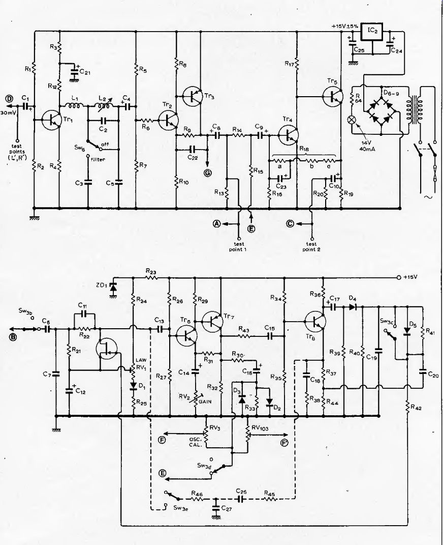
Fig. 12. Circuit of one channel of the stereo Dolby B noise reduction unit.
Upper circuit is of main signal path, input at D, output at C. Point G feeds meter circuits of Fig. 15, while point A or point C feeds the side-path input B (bottom), according to whether encode or decode is switched by the interface circuit of Fig. 13. Side-path output from E is combined with main signal via Rl5. Connection shown with broken line forms a Wien bridge oscillator to provide a 400-Hz calibration tone.
Output is via oscillator level controls R Vj, and feeds point F in Fig. 13.
This additional circuitry, including potentiometers and Sw3b.e is used on one channel only (the left channel in the kit design). Resistor R:i3 is omitted in left channel if used as an oscillator.
Setting-up circuitry (in kit version)
Because this noise reduction unit can be used with a variety of tape recorders, the side-path includes its own 400Hz oscillator so tliat a standard-level tone can be recorded, played back and the processor calibrated for the particular tape used. The 400Hz tone is obtained by switching the side-path circuit (Sw3(,), to form a Wien-bridge oscillator with R40, C27, Cjb and R45 around Tr106, ]07 & Trl08, Oscillator output is taken from point E and applied via point F to the processor input, D, by Swjc and Sw3a, Switch Swjf alters the control time constant to prevent oscillator instability. Potentiometers RV3 and RV103 are used to set the level of the 400Hz tone for both left and right channels respectively. but only the left-channel sidepath circuit is wired to oscillate. This adjustment, and that of RVj, S01 and RV2,i02, are made with the aid of the right channel meter, calibrated in the kit design by a further oscillator (Fig. 14), This oscillator provides a well-defined output of 580mV, whose accuracy is determined by the supply line regulation of 5%. For the kit design the oscillator of Fig. 14, including the components shown by the broken lines and with its output feeding the attenuator of and R61 (a), provides the 580mV signal to calibrate the meter. After this calibration, R4g and R57 are removed and the second network, (b), of Fig. 14 wired in to provide a 5kHz sinewave source for aligning the circuit. The input filter coil L2 is used temporarily in this oscillator.
The two meter circuits of the kit design use two parts of an LM3900 Norton or current-differencing amplifier in a "perfect diode" arrangement, Fig. 15. Because the circuit is set-up at low levels, Rsj is temporarily reduced in value to increase sensitivity for these measurements. Additional current gain is provided by Tr9, Oniy the right-channel meter is used to measure the low levels.
-----------------
---
Components
Electrolytic capacitors are 16-voll working (except G24, C14, ,14, C29, and C,,, u,. Polystyrene capacitors may be marked with a "k" multiplier instead of "n".. (Polyester capacitors are colour coded.)
Inductors
L, 36mH ± 5% (Toko 30569 in kit)
L2 23 mH, Q? 60 (Toko 30568 in kit)
Transformer 240/17V nominal Other parts (all supplied in kit)
Dual 200-/J.A meter, plastic foam, wire-ended 14-V 40-mA lamp • fuse and holder • 7-buttoi! switch unit, 6-pole switch (Swj), mains switch • two printed boards • three knobs • three DIN sockets • chassis,, front panel, screws, tag strip, meter bracket • labels, connecting, wire, mains lead, strain relief bush • cabinet.
------------------
Circuit options
The unit can of course be constructed
» without using the kit. Provided that normal good practice is followed in circuit construction, assembly on Lektrokit or Vero circuit boards should be no problem. But for those constructors unfamiliar with normal practice, we recommend using either the full kit or a smaller p.c. board. This smaller board is for a single-channel processor without the switching and setting-up circuitry of the full stereo board, and is available separately.
If similar functions to those of the kit are required the same switching arrangements of Fig. 13 can be used.
Selected field-effect transistors are available separately through Wireless World (see panel). The simplest possible circuit option is for playback of B-encoded cassettes.
Designed for use as a noise reduction unit, the circuits have many more facilities than required for a playback-only processor; nevertheless, Fig, 12 can be used in this application with an enormous simplification of the switching, The circuit can be permanently wired in the decode mode, and needs only the switch Svv4 in Fig. 13. Point C is permanently wired to point B via Sw4 and the signal from the head amplifier wired to point D via the play cal. control. The filter components can be omitted if use is to be always limited to playback of recorded cassettes.
Inclusion of the facility for decoding B type FM transmissions can be added to this basic design simply by retaining Sw2a and Sw1a and associated input circuitry. More simply, the two switches can be combined into one. Maximum cost-effectiveness is clearly obtained with the encode/decode version, as almost all of the circuitry is common to both modes --see Fig. 9, May issue, page 204. The: first basic simplification possible of this switchable family is omission of the FM facility.
Switch Sw2 is eliminated, being permanently wired in the position shown in Fig. 13.
------
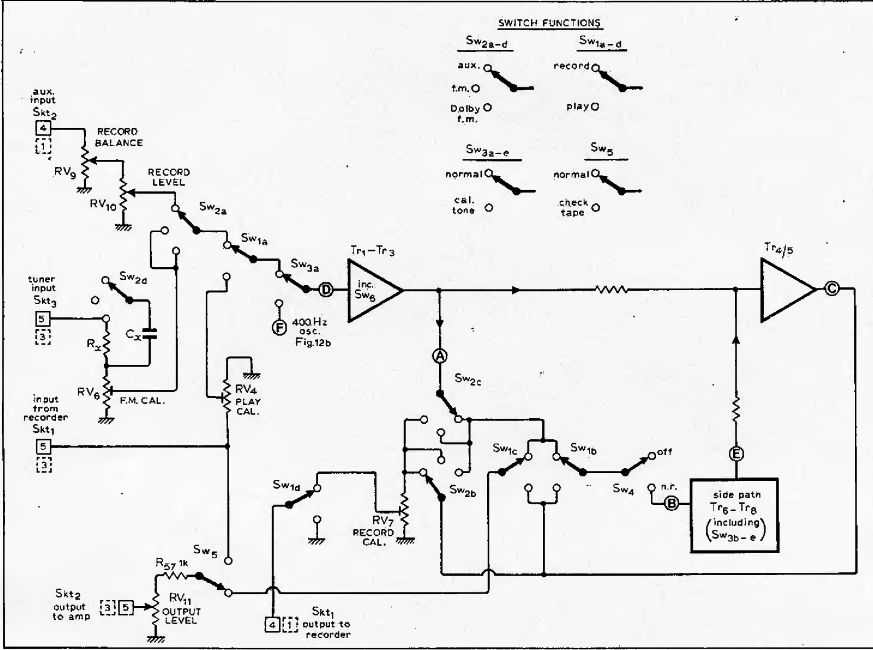
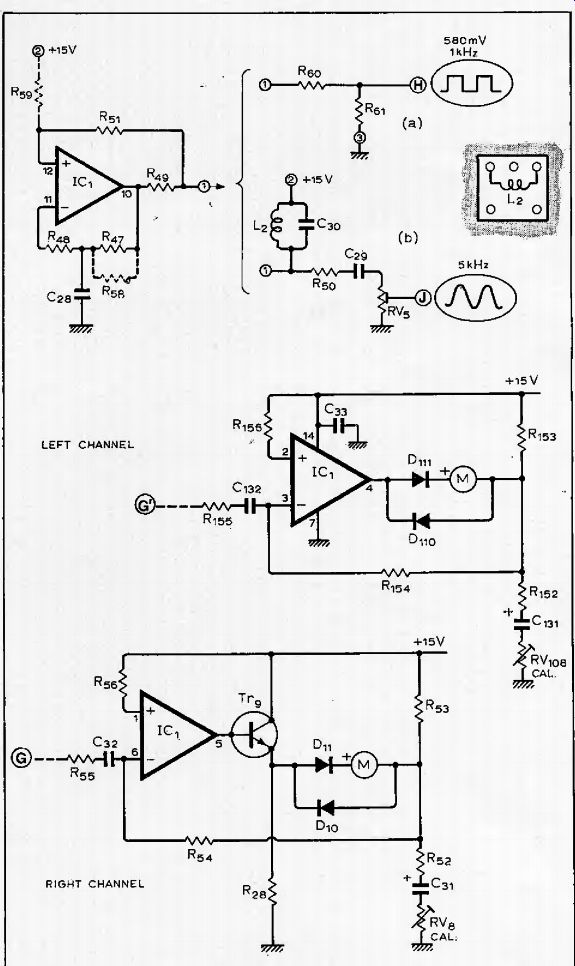
Fig. 14.Oscillator circuit used in kit for generating a 1-kHz tone (a) for calibrating the meters. Though a square wave, the magnitude is chosen to give the same reading as a 5S0-mV sine wave. Circuit is subsequently used to provide a 5-kHz circuit alignment tone at (b) by temporarily using L^.
Fig. 15. Meter circuits using "perfect" diode arrangement. Right-channel meter circuit at bottom includes extra gain to allow measurement of low signal levels during alignment.
If a separate audio oscillator is available, the circuit of Fig. 14 version (b), need not be used. If the unit is to be built into a tape machine you may wish to omit the meter circuits, and adopt a simpler switching scheme. But you would then need an a.c. millivoltmeter for setting up. The 400Hz oscillator wiring, shown by the broken line in Fig. 12, could also be omitted if the same tape is always used. We recommend retention of this feature to take account of tapes with different sensitivities (see part three).
Setting-up procedure
For proper operation, the encoding and decoding signal processors and the intervening signal channel must be matched at all frequencies of interest and all levels. Any errors in channel gain, on a wideband or frequency-selective basis, can produce a mismatch, or error, in overall response. But first, the circuit must be adjusted to provide the correct degree of low-level hi.
emphasis and de-emphasis (10dB at 5kHz), and the correct threshold level.
Matching between encode and decode modes must be checked. Then the processor must be level-matched to the equipment and media (tape of FM radio) it is to be used with; to be covered in part three.
If the circuit of Fig. 12 is constructed Fig. 13, Switching interface for one channel of Dolby B processor allows decoding and encoding of tapes, recording and simultaneous decoding Dolby FM transmissions (current in the USA), encoding of normal FM transmissions, and a normal signal for monitoring during recording.
This arrangement is used in the kit design, but could be simplified in other constructions, for instance by omitting Dolby FM provision given by Sw? Switch Sw^g appears in both channels, but remainder of Sw3 is used in one channel only. Pin numbers on kit DIN sockets are indicated for both channels (dashed boxes for left). without using the kit, apply the following setting-up procedure (see part 3 for kit). You will need an a.c. millivoltmeter and an oscillator, unless you adopt the technique using the circuits of Fig. 14 & 15, as in the kit design.
Before starting, make sure that the FET, gates are shorted to earth. Start in the record mode with the noise reduction switched out (also the cal. tone off and the filter out, if used).
-Set law control RV, to produce maximum positive voltage on the FET source.
-Feed in 5kHz signal at a level to give 17.5mV at test point 1 and note signal level at test point 2.
-Switch in noise reduction and adjust gain control RV2 to give a I0±0.25dB rise at test point 2. Note signal level.
-Remote FET gate short and adjust law control RV, for a 2±0.25dB drop at test point 2.
-Replace gate short and check that level returns to that identified by*. Finally, remove gate short.
Encode/decode matching check. Without altering the control settings, switch to play mode.
-Switch out noise reduction and short FET gate.
-Feed in 5kHz signal at a level to give 44mV at test point 2.
-Check that signal drops by 10±0.5dB when noise reduction is switched in.
-Remove gate short and switch in noise reduction. Check that signal at test point 2 is 17.5mV ± 0.5dB. Decode-only processor. As with the switchable encode/decode version, ensure that FET gates are shorted to earth, and switch noise reduction off.
-Set law control RVj to pinch-off FET i.e. maximum positive voltage on source.
-Feed in 5kHz signal to give a level of 44mV at test point 2.
-Switch in noise reduction and adjust gain control RV2 to give a fall of 10d:0.25dB at test point 2.
Note signal level*.
-Remove gate short and adjust law control RVj to give a rise of 2±0.25dB at test point 2 (should be 17.5mV).
-Replace FET gate and check that level returns to that indicated by*
-Remove gate short.
Meter and oscillator calibration. If the meter circuits are to be fitted, calibrate them by applying a 580mV tone and adjusting for a 0dB reading. One of the meters can then be used to calibrate the 400Hz oscillator level, if used. (The circuit of Fig. 14 from the kit design could be used if fed from a sufficiently well-regulated supply line; 5% in the circuit of Fig. 12.)
-Apply input signal to point D to give 580mV at point G.
-Adjust RV8 for 0dB meter reading.
-Operate cal. tone switch (if oscillator fitted),
-Adjust RV3 to give 0dB meter reading.
The unit is now ready for use. But to ensure compatibility with commercially-available Dolby tapes, and to ensure interchangeability of tapes from machine to machine, it must be calibrated using a level-setting tape, to be detailed in part three of this article.
Kit construction
Successful operation of the unit depends on a number of factors. As well as proper matching of the unit, strict adherence to component tolerances and alignment procedure, use of selected FETs, and a low ripple in the supply line are all essential to correct operation.
For these reasons the parts for the unit are available as a complete kit.
The printed board of the kit is designed to keep wiring to an absolute minimum; it is for this reason that switches, calibration controls, and DIN sockets are board-mounted types. First thoughts indicated a double-sided board would be needed together with plated-through holes, but this would make an expensive board. The same effect could be achieved with a larger single-sided board but would result in a large number of links. The relatively large number of controls finally decided the format. To keep board length down, some controls had to be mounted above others, and as there was to be a minimum of wiring, the top controls are mounted on to a separate board. The advantage of this sandwich board technique is a saving of about 24 links.
In the instructions, component numbers for the left-channel have 100 added to the number for the right channel: thus R^ is the left channel component corresponding to R2] in the right channel.
Kit assembly instructions
A number of pins are supplied with each kit; in fitting them insert from the track side of the board, tap down lightly with a hammer and solder into place. Insert pins as follows
-two pins for the transformer input, marked Vin close to IC2
-four pins for right and left meter outputs, marked ±M.R., ± M.L.
-two pins in resistor position
-one pin at the end of R5, close to ICj (see Fig. 16)
-one pin each at the end of R55, 155 close to C32 (see Fig. 16)
-three pins in the position, marked with broken lines, next to IC^
-one pin at the 5kHz oscillator output point, marked "osc"
-six pins in the holes marked E, R, L; E, r and 1 between socket Skt3 and C7.
There are seven links to be inserted on the main board; two further links are used if a tuner is to be connected to the auxiliary input socket, rather than the tuner input. The two FET-gate links should be looped, to allow easy breaking and making of the gate during alignment. Close-tolerance components, i.e. resistors of 2% tolerance or better and capacitors of 5% tolerance or better, are separately packed.
-Insert seven or nine links, as appropriate.
-Mount close-tolerance resistors
^21,121
R37 R 14,114 R,i R ]Sb;118b
-Follow with close-tolerance capacitors
C2M2 --Cj 103 --Cg.ios --Ct.io? CiLiu-
-Mount the remaining fixed resistors and capacitors identified on board, excepting C30, R47) Ras,^. Make sure electrolytic capacitors are inserted the correct way round, that is, indented end to the hole marked +, Note that Rjg to R64, R^ and Cx will be left over, in addition to the four components already mentioned. -Add pre-set potentiometers RVU
RVjjqj --RVV --RVB RV. 3,103 RV, in, --
There are four types of diodes, easily identified by the quantities supplied.
Zener diodes have the connections of the E-line package, the + lead corresponding to the collector position in Fig. 17. Of the others, the OA91 germanium diodes will be the largest and glass-encapsulated; the rectifier diodes will be the four plastics-encapsulated ones; and the lN914s should be the smallest, of either glass or plastics; The band-end is to correspond with + on the board.
Base connections for the transistors are shown in Fig. 17. The field-effect transistors may have various markings but nevertheless will have been specially selected. Transistors Tr]tl01 and Tr5105 must be type ZTX109C, but the remaining n-p-n type may be supplied as either ZTXA11 or 109C. ICj is located so that the end. having the indent or other marking corresponds with the board marking. Solder next in place diodes ZDj 101, D[,ioi 1° Ds.iosto Dq, D, 1 and D.
-transistors
Trj ]01 Tr5105 (ZTX109C), Tr3103 and Tr7107 (ZTXA21), field effect types, followed by remainder
-integrated circuits IC, IC2.
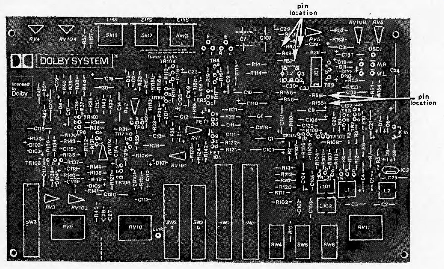
Fig. 16. Main board markings show seven essential links plus two optional
links, for use if a tuner is to be applied to auxiliary socfeet. Some pin locations
are shown. (Boards in kit have a slightly different track arrangement.)
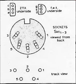
Fig. 17. Socket connections, viewed from "holes". If E-line zener
diode is used, as supplied in kit, the + sign on the board should correspond
with the position of the collector lead in the E-line package shown right.
When positioning the three DIN sockets make sure they are vertical and in line with each other, for appearance's sake.
Check functioning of the push-button switches as they are difficult to remove once soldered. As the switch board markings will be covered by the switches, identify them before assembly. Take care to push them fully into the board and ensure, that they fit squarely; any skew will result in misalignment with the front panel. Fit and solder
-three DIN sockets
-switches Sw1 to Sw6 inductors L^( L|Q2, but not
Sub-printed board
Components are fitted on to trie track side of the subsidiary printed board.
-Solder components Cx. R^.
-Solder potentiometers RV61(j6, ^^7,107*
Attach. plastics adjuster inserts into rv6j rv7,
-Cut off potentiometer legs flush with the board.
The sub-board should be spaced about 0.09m away from the top of the main switches to ensure potentiometer centers line up with the front panel holes. Matchsticks form convenient spacers.
-Lay matchsticks on Sw2a and Sw,
-Position sub-board, check alignment and solder
-Join areas on sub-board marked R, L, r, 1 to corresponding points on main board using twin-screened cable. Earth at one end only to points marked E.
-Connect link point on sub-board to link point on main board almost underneath.
-Insert links marked "Mpx" for use with 25-(iS B-Type FM transmissions.
Returning to the main board, be careful to align potentiometer spindles horizontally.
-Solder dual potentiometers RVg (log/reverse log). RVlfl. RV,,.
-Check underside of board for solder shorting and dry joints.
-Crop leads to avoid touching chassis.
-Insert thin sheet of card between board and chassis.
-Fix board in position with 6BA screws, Off-board assembly.
Fix in position
-transformer
-fuseholder
-mains switch to meter/switch bracket
-bracket with tag strip under one screw.
At this point you can tape the meter to the bracket, temporarily with the piece of foam plastic material between; normally the meter will be held in position by the front panel. Continue with off-board wiring
-transformer secondary to two points of tag strip (not earth tag)
-the two tags to Vin terminals on board
-meter illumination tamp, in series with R^, to the two tags, the junction to a third tag (not earth tag)
-meter terminals to ± MR. and ±M.L. on board (note + terminals on meter)
-mains cable brown lead to transformer primary via fuseholder and switch
-mains cable blue lead, via switch to transformer primary
-mains cable earth lead to earthed tag on strip
-insert strain-relief bush in hole and pass cable through
-stick on labels: one to identify sockets and play calibration potentiometers, the Dolby Laboratories label on the rear close to socket Skt3J and the third inside chassis close to transformer.
----------------
Dolby noise reducer 3 --Kit alignment and calibration
Constructors who build a Dolby-B processor without using the full WW kit have the option of using the power supply included in the circuit of Fig. 12 or of using an alternative one, for instance one built into existing equipment. Component values for the circuit of Fig. 12 have been optimized to provide an overload margin of 16dB (equivalent to 1200nWb/m on open reel) for a 15-volt supply, but voltages between 15 and 24 volts could be used provided component voltage ratings are chosen appropriately. The main requirement is that supply ripple be less than 200 uV RMS Current consumption at 15 volts is 20mA per processor; with IC1 and IC2 it is 30mA. The voltage regulator Ic2, whose output is 15 volts ± 5%, is essential if the meter calibration oscillator of Fig. 14 is used. Input to the regulator should be not greater than 25V and not less than 18.25V. Kit setting-up procedure
The procedure for setting up the kit design is a little more elaborate than the basic alignment instructions because it is designed to eliminate necessity for additional equipment i.e. a.c. milli-voltmeter and variable-frequency AF oscillator. It therefore includes a facility for generating a 5kHz circuit alignment tone, as well as a 400Hz calibration tone.
Two meter amplifiers, and a 580mV source (1kHz oscillator) to calibrate the meters, are included to obviate the need for an a.c. millivoltmeter.
In using the in-built meter scale in setting up, it is better to use close-tolerance resistors in an attenuator so that all measurements can be made at one meter reading (0dB). Errors in meter reading are minimized by this technique, and errors due to an inaccurate scale eliminated.
Right-channel meter calibration
The unit is aligned using part of IC, as a meter calibration oscillator. The amplifier section of IC, based on pins 10, 11 and 12 is first used as shown in Fig, 14.
In this mode the amplifier is wired as an astable multivibrator switching between the 15V supply rail and 0V, with a mark-to-space ratio of about 1:1 and a frequency of around 1kHz. The real voltage swing is a little less due to saturation voltages, but is highly repeatable from one sample to another.
-Connect resistor R5ft (3.9MO) from the pin at Rj, to pin 2 or the L,' position.
-Wire R58 (lOkO) in parallel with R47 (1MQ) across the pins at R47 position,
-Form an attenuator with Rrj0 (HOkO 2%) and Rei (lOkfl 2%) in series, Fig. 14, earthing the end of R61 by connecting to pin 3 of L2'and connecting ROT to pin 1.
-Solder one end each of Rgg (330k-O 2%) and Rl55 (330kn) to their pins.
Take the other end of R5g to the junction of R6q, R6] (R155 remaining floating). Switch on.
-Adjust RV8 (Fig. 15) until the r.h. meter reads 0dB. Switch off.
-Remove R56, R5g, RS9, R6tt, R61 and do not alter the setting of RV8.
--------------------------
Typical performance
Noise reduction: better than 9dB weighted
Clipping level: 16.5dB above Dolby level (measured at 1 % third harmonic content)
Harmonic distortion: 0 1 % at Dolby level (typically 0.05% over most of band, rising to a maximum of 0.12%) Signal-to-noise ratio: 66dB (20Hz to 20kHz, signal at Dolby level)
Approximate voltage readings (AVO
--
-------------------------
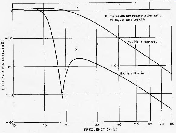
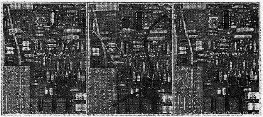
Fig. 18. First part in setting-up procedure for kit version (left) shows arrangement
used in calibrating the right-channel meter. For aligning the noise reduction
circuit the meter calibration oscillator is changed to a 5kHz oscillator, using
L? temporarily in theL2' position (centre), its output, via the "osc" pin,
is taken to the processor input (R' for the right channel). To calibrate the
400Hz oscillator, L2 is put in its normal position, the i.e. oscillator disabled,
and the oscillator output taken from TP1 or TP101 (right).
Circuit alignment
The now-calibrated r.h. meter is used to set the gain and FET bias controls of both left and right processors with the help of a 5-kHz oscillator, Fig. 14, adapted from the 1-kHz oscillator circuit by using arrangement (b).
-Solder C3() in position, removing and replacing the PCB
-Solder L2 on to pins 1 and 2 of the L2 position. Gently screw in the core.
Right-channel circuit alignment.
-Connect R61 (10 k-O 2%) between the R55 pin and test point 1 (TP1) on the sub-board.
-wire the oscillator pin, marked "osc." to the sub-board pin marked R' (input to processor).
-Set RV5 (oscillator level) fully anticlockwise. Check that no plugs are connected into the sockets.
Set RV oa fully anticlockwise.
Switch on.
-Select the auxiliary position for Sw2.
Set the balance control RV9 to mid-position and the input level control RV)0 fully clockwise,
-Ensure the calibration tone switch Sw3, the noise reduce switch Sw4, and the 19-kHz filter switch Sw6 are in the off position (out), and the check tape switch Sw5 is in the normal position (out).
-Check that the FET gates have previously been shorted to ground by two looped links.
-Turn the law control RV] fully clockwise to pinch-off FET
-Switch Swj to record and adjust RV5 until the meter reads 0dB (equivalent to 17.5mV at TP1), Switch off.
-Transfer the end of R61 from TP1 on the sub-board to TP2 and switch on. Meter should read within ±. 1dB of the previous, 0-dB reading. Note actual reading *. Switch off.
-Solder R62 (15kQ 2%) and R63 (6.8k-O) in series with R6J (i.e. between the R^ pin and TP2), decreasing meter sensitivity by 10dB. Switch on and check meter reading reduces by roughly two thirds.
-Switch on noise reduction, Sw4 and adjust RV2 (gain) to bring back meter reading to that noted above at *. Switch off.
-Cut the FET gate short for the right-hand channel with wire cutters and short-circuit R63 increasing meter sensitivity by 2dB. Switch on.
-Adjust RV (law) until meter reads as noted above, at *. Switch off.
-Re-apply FET gate short and replace R63. Switch on and check meter still reads as above, at * Switch off. Remove gate short.
Fig. 18. First part in setting-up procedure for kit version (left) shows arrangement used in calibrating the right-channel meter. For aligning the noise reduction circuit the meter calibration oscillator is changed to a 5kHz oscillator, using L? temporarily in theL2' position (centre), its output, via the "osc" pin, is taken to the processor input (R' for the right channel). To calibrate the 400Hz oscillator, L2 is put in its normal position, the i.e. oscillator disabled, and the oscillator output taken from TP1 or TP101 (right).
---- Amplitude response with and without 19kHz filter.
Encode/decode matching check.
-Switch Sw, to play and switch noise reduction off, SW4.
-Short-circuit R63, leaving R61 and R62 connected. Set RV4104 fully clockwise. Switch on.
-Adjust 5-kHz oscillator output level control RV until meter reads 0dB (equivalent to 44mV at TP2). Switch off.
-Switch noise reduction on, Sw4.
Short-circuit R62 and Rgj so that only R61 is in circuit. Switch on.
Meter should read 0dB to within ± 1dB. Switch off.
Left-channel circuit alignment. Now repeat this process for the left channel, starting from the point of connecting Rfil between the R55 pin, (not R^) and the test point --now to be TP101 --on the sub-board. Note that the right channel meter, being calibrated, is still used in setting up the left channel, and that TRIO I is to be read for TP 1, TP 102 for TP2, RV 10j for RV,, RV102 for RV2, and that the left-channel FET gate-shorting loop is now implied. The "osc" pin is to be connected to the point L' on the sub-board at the appropriate time. After repeating for the left channel, switch off. The gain and law adjustments, are how complete.
-Remove the FET gate shorts, R,;,, R62 and L1, inserting L2 into its normal (final) location.
400Hz oscillator calibration
-Solder one end of R55 to its pin and connect the other end to TP I.
-Short pins I and Sf at the Lj' position, and remove the wire from osc pin to point L'. Switch on.
-Switch Sw! to record, press the noise reduce switch Sw4 off and switch on the 400-Hz calibration tone oscillator, Sw3.
-Adjust RVj (oscillator level) until the right-channel meter reads (MB. Switch off.
-Transfer the end of R55 from TP1 to TP101 and switch on. Adjust RV103 until the r.h. meter reads 0-db.
-Repeat this procedure because of a slight interaction between RV3 and RVjqj. Switch off.
Left-channel meter calibration
-Disconnect R5g from TP101 and connect the free end .of R,55 to TPlOl and switch on.
-Adjust RVi08 to obtain 0dB at the left-channel meter, being careful not to disturb RVf,. Switch off the cal. tone oscillator. Switch off.
19kHz filter adjustment
-Wire R1S5. permanently onto the main board, replace R55 with R6I and connect free end to TP1.
-Connect an FM stereo tuner to the auxiliary input and with the aux-tuner links wired in, switch on and tune to a BBC stereo test transmission.* Alternatively, if a high accuracy (±50Hz) 19kHz oscillator is available, connect its output to point R' on the sub-board.
-With zero AF modulation,* adjust the record level control RV10 to give a 0dB meter reading. Switch the 19kHz filter on, Sw6.
-Adjust L; for minimum reading on the right-channel meter. Do not adjust L; or L101. Increase record level for sharper null near tuning point.
Repeat for the left channel starting by transferring end of R61 from TP1 to TP101, and adjusting L102 for minimum reading. (In using a 19kHz oscillator, connect to point L' on the sub-board and transfer R61 lead from TP1. to TP101 before adjusting L102.)
Calibration
To ensure interchangeability of all Dolby B-encoded tapes and of Dolby B-equipped machines, the voltage levels in the processors must be related to flux levels on the tape. A certain amplitude level is used that bears a fixed relationship to the noise reduction parameters and to conditions between encoder and decoder. The level chosen corresponds with a flux on open-reel tapes and cartridges of 185nWb/m, with 200nWb/m for cassette tapes, with a deviation of 37.5kHz on FM transmissions, and with a voltage level at the processor output of 580mV RMS
This level, often called Dolby level, should not be taken to imply an operating level If the level-setting meters in the unit, are to be used as modulation-depth meters, a mark may be made on the meter to indicate the reference level. Whilst setting this level equal to 0VU on meters can often lead to reasonable modulation depths, this is not always the case: for cassette recorders it is best set at + 3VU, The 400117 oscillator and tapes recorded with a 400Hz tone to the above level are used in calibrating units, once the circuitry has been set up. When playing or recording the standard flux level, the 580mV level is set by adjusting the play calibration potentiometers during play, and the record calibration potentiometers during recording.
* * Experience has shown that a better method of disabling the 5kHz oscillator is to remove R 47.
* Stereophonic test transmissions are broadcast about four minutes after the close of Radio 3 programs on Mondays and Saturdays. The zero a.f, modulation part occurs about 11 minutes after the start and lasts for nearly two minutes. ]
------------
--------- An alternative to the kit design is this single-channel processor, using the circuit of Fig. 12 but excluding power supply, alignment and calibration circuitry (track diagram will be given in a subsequent issue.)
Playback-only decks and units. As the signal levels on encoded tape cassettes are to be related to those ip the decoder during, playback only, the 400Hz oscillator is not required and calibration is achieved with a calibration cassette, containing the reference flux.
Switch noise reduction off.
Play calibration tape. Set play gain control on tape deck to 0VU on deck meter, if possible, or to mid-position otherwise.
Adjust play cai, control for 580mV on meter or Dolby level indication, depending on meter used.
Playback gain controls on the recorder in the signal path en route to the processor input should not now be disturbed.
Switchable encode/decode processors.
Playback calibration
Switch to play and switch off noise reduction. Connect millivoltmeter to point G if meters not built-in,
Play calibration tape. Set play gain control on tape deck if fitted to 0VU on deck meter, if possible, otherwise to mid-position.
Adjust play cal. control for 580mV indication.
This completes playback calibration and the play gain controls on the tape deck should not be altered. Adjust listening level with the Output level control following the decoder output (as in Fig.13).
Record calibration
Start by setting record gain control on tape deck to mid-position, if fitted. (If combined with playback gain, do not adjust.)
Switch to record.
Fit blank tape (as recommended by maker or for which bias is correctly adjusted) and feed in 400Hz at points from external or internal oscillator. (If unit has been built into cassette machine and 400Hz input is via line input socket, adjust record level control so that meter reads 580mV, or Dolby level.)
Record on tape for a few seconds, rewind and playback, switching to play on the noise reduction circuit as well as on the deck.
Note whether meter shows about or below 580m V, or Dolby level.
Make small adjustment to record cal. controls in appropriate direction and record 400Hz tone again, observing meter reading on playback. Repeat this procedure as many times as necessary to obtain correct reading.
This completes record calibration for tapes, if the circuit of Fig.13 or similar has been adopted, recording level is adjusted with record balance and level controls on the noise reduction unit, the level being judged by the tape deck's normal meters.
When the noise reduction unit is connected to a three-head machine with a simultaneous monitoring facility the tape signal may be monitored in its encoded form by operating the check tape switch.
Simultaneous encode/decode circuits.
Constructors with three-head machines having a simultaneous monitoring facility can use single-processor boards permanently wired, in the encode and decode modes. If provision for encoded FM transmissions is required switching, must be arranged so that encoding does not take place during recording. A monitor switch can be provided at the input to the decoder, to switch from tape, via a play cal. potentiometer, to source i.e. a connection to the encoder output via a 580-30mV attenuator, Fig 19.
Playback calibration procedure is as above, but record calibration is simplified.
Set record level controls on tape recorder to mid-position. Set monitor switch to tape.
Record on blank tape, operating the calibration tone switch or injecting a 400Hz tone from an external oscillator.
Adjust record cal. control so that meter reads 580mV, or Dolby level.
FM calibration. If you wish to set the controls for encoded FM transmissions, currently being transmitted by stations in the USA, an approximate calibration can be achieved by tuning to a local station, switching to FM or Dolby FM and setting the FM cal. control to give meter readings similar to those obtained when playing pre-recorded tapes. More accurate adjustment can be obtained if a station can be received which transmits the 400H2 calibration tone, identified by a characteristic warbling, or alternatively by using an FM generator, in this last-mentioned case, modulation frequency should be set to about 400Hz with a peak deviation of 37.5kHz (not including pilot tone).
Tune in to whichever of these signals is available.
Switch to record, and to either FM or Dolby FM
Adjust FM cal. control so that meter reads 580mV, or Dolby level.
Using the unit The calibration procedures described theoretically apply to the one tape speed used during calibration. Whether the calibration will hold for different tape speeds depends on the design of the deck, so check calibration when speed is changed. The calibration tape available can be used at 4.75 and 19cm/s, as well as 9.5cm/s. (For 38cm/s tape speed, where the noise spectrum is wideband, applying the B-type system may result in the remaining mid and low-frequency noise becoming more apparent). When the brand of tape is changed it is usually necessary to readjust the record ca). controls, the play cal, setting remaining unchanged. The characteristics of cassette tapes are more critical, and changing brand will normally require adjustment of bias (and equalization when using Cr02 tapes). When the unit is connected to the normal input and output points of a tape recorder, the recorders own input and output controls from part of the calibrated system. The settings used during calibration should not be disturbed, input and output level controls being provided on the noise reduction unit, and it is a good idea to mark the tape recorder control settings.
The amplitude response of the tape recorder must be flat and its gain unity, measured between point G of the processor in record and play, to ensure correct operation, so that the signal voltage in the decoder is the same as that at the encoder (to within 2dB). If there is a bandwidth restriction between encoder and decoder, e.g. if the response of the recorder does not extend up to at least 10kHz, a non-complementary situation arises, unless of course the encoder input bandwidth is similarly limited.
In using the unit don't forget that it will only reduce noise generated after the encoder and before the decoder. If the input signal is noisy in itself or is made noisy by poor circuitry prior to encoding, this noise will be reproduced unaltered along with the signal. In some cassette decks, the line inputs are attenuated prior to amplification by a sometimes noisy microphone preamplifier.
As the sensitivity of the processor is of the order of 30mV, a line input amplifier is not required when the circuits are built into a tape recorder, and the input signal should be taken directly to the input gain control via a switch, or socket with switch, to disconnect the microphone pre-amplifier. It's a good idea too to make sure any automatic level limiter operates only in the microphone input and not in the line input.
-----------------
Change of time-constant for encoded FM transmissions
There are two commonly used pre-emphasis time constants, 50 us and 75 uS, Under certain conditions, these values can lead to reduced modulation at low and medium frequencies or severe amplitude distortion at high frequencies. In the USA the FCC has approved Dolby Laboratories' proposal of using 25 us for encoded transmissions, and to receive such broadcasts it is necessary to alter the de-emphasis time constant. In the circuit of Fig.13 this is achieved with components Rx and Cx, values being given in the components list on page 259 (June) for the change from 75 to 25 us and for a change from 50 to 25 uS (not yet authorized in 50 us countries). When recording such broadcasts the encoding function of the noise reduction unit is clearly not required and the "Dolby f.m." switch position automatically switches off the encoding function. Application of the Dolby B system to FM broadcasting is discussed in two articles in the Journal of the Audio Engineering Society, June.1973, pp.351-62, and briefly in the July 1974 issue of Wireless World, page 237.
-----------------
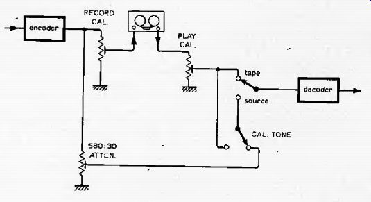
Fig. 19. Monitor switch arrangement for permanently-wired processors in three-head machines.
----------
Letters to the Editor
DOLBY KIT FILTER ADJUSTMENT
The use of the BBC test transmissions seemed to me to be a little hit-and-miss for setting-up the 19kHz fitter of the Dolby noise reducer (July issue) since the vital zero modulation part only lasts for about two minutes. I also did not have a suitable signal generator available.
However, a little thought showed that a precise 19-kHz signal was available from pin 10 of my MCI310 stereo decoder when receiving a stereo signal. Since thas is the signal that the filter is required to attenuate it seemed logical to use this for alignment purposes. The signal was applied with a 2M-O potentiometer in series and alignment was easily completed using the signal generator instructions.
There was possibly some modulation of the signal as the meter flickered slightly, but in spite of this the null was very precise.
Your readers may find this of interest to enable them to set up their kits without having to wait for Radio 3 to close down.