Simple square-law circuit gives 100 dB dynamic range
The wideband compander described can preserve the dynamic range of virtually any input signal when recorded by a normal tape recorder. Operational amplifiers and matched photocells allow accurate compansion with no necessity for calibration or care in recording levels. The unit can be used in compression mode for recording or playback in noisy environments, and for speech signals.
The dynamic range of tape recorders has never been adequate for high quality reproduction. If a high input level is used in an attempt to decrease the effects of tape noise, distortion results on loud passages and transients are severely distorted. Reducing the level to allow even moderate transients to be captured with little distortion means that small signals will be lost in noise. A good quality half-track reel-to-reel machine can expect a signal-to-noise ratio of about 60dB and because normal audio signals vary more than this, most recording is caught in the compromise between noise and signal distortion.
Several commercial devices are available to solve these noise problems. Dolby A systems are compressor-expanders that work in a number of frequency bands in the audio spectrum. They are very virtuous but are beyond the stage where home construction can be contemplated. The Burwen compressor-expander' is a device that works over the whole audio spectrum, using cube-root compression and cubic expansion, along with some equalization. Circuits for this compander were not available to the author, but the appeal of the basic system was such that a design suitable for home construction was sought and finally achieved. A recent advertisement from DBX indicates their companders may be similar to the one described here. Recently, SeiD has detailed a circuit for compression only. Stuart [3] has described several other active systems but not the power law compander so its basic merits will be given below.
If a compressor is designed to take an input audio signal I of large dynamic range and compress it to an output θ in accordance with the law
θ = kI
... where k, is a constant and n is a positive integer (it could be fractional, but the electronics is more complicated), then the dynamic range of 0 can be such that a tape recorder can faithfully record this signal. We assume that the playback signal P is equal to 6 for a unity gain recorder. (There will be some error and its effect will be discussed later). Then if an expander is made which gives a final output signal S given by then ...
S = k.p = k^kf l
... and hence except for the constants, which will vary if level controls are altered, the signal S is a scaled version of the original input 1. For domestic use it is argued that n = 2 is a good choice. An input signal of ID 0-db variation will be compressed to 50dB at the tape, thereby achieving a good performance with modest recorders. The n = 3 system used by Burwen [1] shows deficiencies when used with domestic recorders having considerable variations in response with frequency. If the recorder has a response error of XdB then the final expanded signal will have an error of nX dB. A wide spectrum signal such as normal audio will relieve these difficulties, but if a 6dB variation in response exists, the cubic system is impractical.
Recent articles on the Dolby B noise reducer give much useful information on compansion in general and prompt a comparison between wideband compansion and Dolby B. 1 have always preferred the transmission of program material by simple 2:1 logarithmic compression, rather than Dolby B methods, because the frequency response is then not altered by receivers not equipped with standard decoders. I fear the extra top will become so enticing to people that the Dolby decoders will hardly find use. In essence it boils down to a preference for distortion in level as opposed to distortion in frequency response.
An interesting view of Dolby methods from the BBC recently appeared in a letter to the editor. A real advantage of the Dolby B approach is that only high frequencies are altered, and gain changes can be made so quickly that no noticeable noise modulation and breathing exist. Present-day wideband companders can partially solve these problems as well. Firstly, the attack time can be very short, so that extra pre-emphasis can be used with a consequent reduction in noise. This however, creates more incompatibility with existing components and pre-emphasis is not used in the present design. Secondly, by using special filters to eliminate self-modulation distortion, but still retaining a rapid decay-time, the effects of noise modulation and breathing are subjectively reduced. This concept is used in this design. A definite advantage of wideband compansion is the much greater degree of noise reduction for low-level signals, as will be evident later. Professional assessments of companders and Dolby systems are given in recent reviews. For the moment it is to be appreciated that wideband compansion prevents overloading the recorder, reduces the effects of noise at low signal levels, and virtually makes recording level controls unnecessary. In addition an accurate power law device will reproduce faithfully irrespective of the settings of the level controls. No reference levels are necessary as in Dolby systems or other non-linear companders.
Requirements
The heart of a compander is a gain-controlled amplifier which can divide or multiply the gain by means of a control voltage. It must be capable of 50 or 60dB gain variation with an accurate characteristic. A good audio bandwidth must be maintained over the whole variation, and the distortion should not exceed 1%. The gain variation must be rapidly programmable as well. A servo system driving a potentiometer would be accurate but too slow. A good figure to shoot for in response time is several milliseconds. This allows even transients to be respectably dealt with.
A well-built transconductance multiplier will satisfy the above characteristics, but it has too much wideband noise. This is due to the necessity of small signal levels at the bases of the multiplying transistors to prevent distortion.
As well as an accurate multiplier-divider, the circuits which caliper the audio level and produce a smooth rectified signal proportional to the amplitude must be accurate and have an attack time less than a few milliseconds. The release time should be rapid to prevent pumping but not rapid enough to cause distortion by "self modulation" of a low-frequency signal.
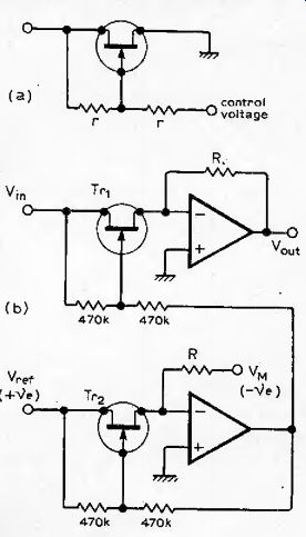
Fig. 1 (a) The distortion of the FET as a voltage-controlled attenuator can
be reduced by driving the gate with an alternating voltage midway between the
source and drain voltages, (b) by using a second matched FET the variation
of the gain can be made proportional to Vm/Vref.
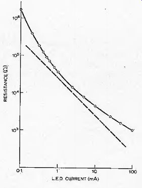
Fig. 2 Curve of photocell resistance versus l.e.d. current for a Clairex CL904Nphotocell
when illuminated by a red LED The unbroken line is drawn through the experimental
points. The dashed line represents ideal behavior.
Experiments
Early experimental attempts at making the multiplier-divider centered on FETs and their source-drain characteristics near the origin.
Distortion is high if the FET is used in a straightforward way, It can. be greatly reduced if the gate is driven not only as a control voltage but as an alternating voltage which is midway between that of the source and the drain as in Fig. 1(a). This gives the device a drain characteristic of odd symmetry. Thus all even harmonics are entirely removed by this "push-pull" technique, and only odd harmonics, mainly third, occur at higher signal levels. The problem still remains that a large gain variation of greater than 30dB is difficult to achieve, and the gain is not a simple function of the control voltage. The last-mentioned problem can be alleviated by using one of a matched pair of FETs (a dual) to generate a specific resistance using an operational amplifier.
In Fig. 1(b), Tr2 has a resistance which is determined by setting the input current of the op-amp equal to zero with due respect for the virtual earth, i.e. V*rrf/R. c. ¦= V„,/R.
Transistor Tr, wiil have the same resistance and the upper circuit, which handles both polarities for audio, will obey a law
'VVF --V„/Rfet = V^/V^.
Thus Vout = VmVM/v ref th vision and multiplication have both been accomplished! This circuit technique must be remembered ' for the multiplier to be described later. It is not suitable in the present form since not enough gain variation is available.
Another method attempted was to make a transconductance multiplier using FETs as the input active elements. They would not be as linear as transistors on a relative basis but since the voltage scale on which they turn on is about a volt as opposed to the 25m V for a transistor, much less attenuation of the input signal is necessary and this together with lower FET noise would reduce the noise to small values. Disadvantages of the design are the difficulty of obtaining division and the requirement of four well-matched FETs.
Photoconductive cells were also considered as possible gain control elements for the multiplier-divider. Initial experiments indicated that when a light-emitting diode was suddenly turned on the coupled photocell would respond with approximately two time constants, one a fast but rather small relative behavior, the other a slower rise of about 10ms to a final conductance level. This is not suitable for a fast-acting gain control circuit. Also the final conductance value was not properly proportional to the LED current. Fig. 2 shows the characteristic of resistance versus current for a CL904N photocell coupled to an LED A straight line of slope -1 would represent ideal behavior.
It was decided to employ op-amps to linearize the cells using the technique mentioned earlier. Fig. 3 shows the basic idea for a multiplier. A divider can be constructed by interchanging the resistor and the photocell as gain-determining elements for the amplifier A,. The LED shines equally onto both photocells. Tracking of the photocells is essential for an accurate power law compansion, but an error does not significantly affect the overall characteristic, see later. From five photocells at least two would track well over factors of 100 change in the resistance.
Experiments with this multiplier-divider showed that a 60dB range was possible and the attack time for a large step increase In the control voltage was about one millisecond, The feedback has thus considerably reduced the sluggishness of the ceil. At low light levels the cell seems to have a longer time constant and a nonlinear network placed in series with the LED maintains good control stability over all voltage levels.
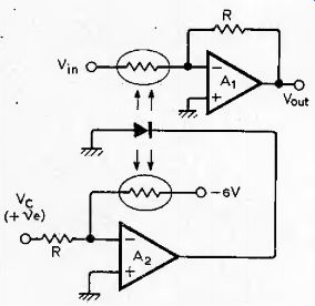
Fig. 3 Photocells and a controlling LED are used here as a multiplier using
a concept similar to that shown in Fig. J (b). For this circuit V' = VrV,„/6,

Fig. 4 Schematic of the circuit used to obtain an absolute value of the audio
signal and produce a control voltage proportional to the peak of the waveform.
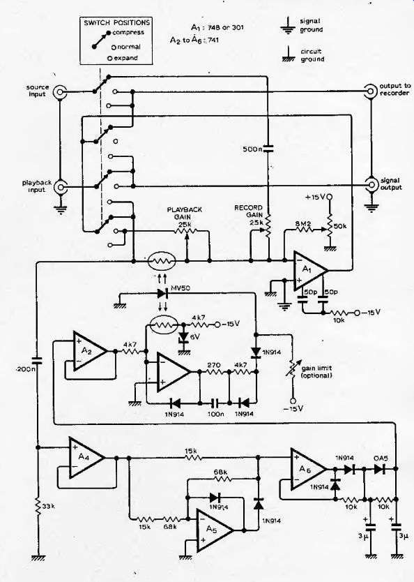
Fig. 5 Compete schematic of the compander, Op-amps are assumed to have ±15V
power supplies. For best performance amplifier A, should have separately decoupled
supplies, The 10k resistor in the compensation should be referred to the
negative supply.
Fig. 4 shows the rectifier circuit that was adopted to produce a direct control voltage for the multiplier-divider. Amplifier Aj has circuitry which creates an absolute value circuit with a gain of 2/3.. Diode Dj is used to create a virtual earth at the inverting Input for positive input signals so that the upper 5k and 10k resistors can form a simple attenuator. This diode also prevents op-amp saturation and hence allows accurate response up to the highest audio frequencies, a feature which many precision rectifier circuits do not have.
Amplifier A3 is a peak detector in which D4 prevents saturation of the op-amp when the input voltage from the absolute value rectifier is lower than the voltage on G,. Another advantage of this diode is more subtle. If a rectified sine wave of constant amplitude is fed into the peak detector, the droop at C, ts much less than in a circuit in which R, is returned to ground rather than the inverting input terminal. This, is so because the negative input terminal follows faithfully the input signal on the n on-inverting input terminal. However, if the audio signal disappears, then Ri is effectively returned to ground and the decay time constant is short. For audio frequencies
>1/2itR1C];
the droop is only as large in this circuit as when R t is returned to ground. Components Rz and C2provide extra filtering and D5 allows the control voltage to rise quickly in the presence of audio transients. The input follower A, is necessary because the input impedance of the absolute value circuit changes with signal polarity.
Circuit description
The complete compander circuit diagram is shown in Fig. 5. Switching allows the circuit to be used as a compressor during recording, and as an expander during playback. In the compression mode, the control voltage acts to decrease the audio gain as a divider. Hence the output 9 will be related to the input by the relations HVc But Vc is derived from the amplitude of the output signal, hence
6. Thus or 9!X vf a square-root compressor. When in the expansion mode, the audio gain is precisely proportional to the control voltage. Hence the final output signal S is related to the playback signal by the relation S0<:
PVC but Vj is derived now from the audio signal P, hence V.^P. Thus S^P^ and a square-law expander results.
If the photocells do not track well, the division or multiplication factor must still be the same function of control voltage, say
/(VJ, because of the way the photocell is switched in the compress and expand modes.
Hence and if we assume again that P = (t (for a good recorder) then S = Pf( V„)=flf(V j = [.
Thus a perfectly complementary system still results. Careful analysis shows that this is true only if the recorder has unity gain, because otherwise the playback signal would produce a different control voltage than that used during recording. Only a power-law behavior of the function f(Vj will preserve the relative level differences. In the present circuit/(x) = x, a simple function indeed.
The major circuit blocks in Fig. 5 can easily be recognized from the earlier discussion, but several features warrant special consideration. The operational amplifier A, used in the multiplier is used in a circuit in which the gain is varied by up to 60dB. At unity inverting gain, a compensation capacitor of about 15pF between pins 1 and 8 (half of that for a voltage follower) is necessary for stability. But this is detrimental to the frequency response when the gain is high (a small amount of feedback), as for example during small signal levels in compression. Pin & comes from the output circuit of the op-amp. Pin 1 is a high impedance point which has a signal referred to the negative supply line. The difficulty occurs when the high level signal from pin 8 is injected into pin 1 through the normal compensation capacitor. The gain is drastically reduced at high audio frequencies. But there is no problem with op-amp stability at these frequencies; instability only occurs near 1MHz. The 10 k-ohm resistor between the two 50pF capacitors shunts the gain reducing signal to the negative supply line thus restoring the gain at audio frequencies while not materially affecting stability considerations at megahertz frequencies.
An important point is the selection of photoconductive cells. Impedances of Ikfl are ideal for op-amp gain determining resistors. Lower values might tend to cause current limiting at high signal levels. It is therefore recommended that the photocells have resistances of not much less than 1 kfl when illuminated by an LED carrying a current of 10mA. The LED can be glued to the two matched photocells (or dual photocell) with clear epoxy,
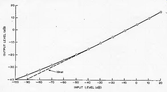
Fig 6 Curve indicates output level versus input level when the compander is
in the compression mode. Note that a 60dB input variation is compressed to
30dB of output variation to be recorded on the tape.
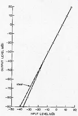
Fig 7 Output level versus input level in decibels for the expansion mode.
A 30dB input variation from the recorder on playback would be expanded to an
output of 60dB to be fed to a power amplifier.
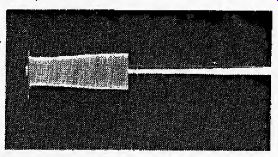
Fig. 8 Oscillograph of the compressor output when the 1kHz input signal is
suddenly increased by about 30dB by a mercury wetted relay. (20ms/div horizontally,
2V/div vertically.)
In a stereo system one has a choice of building a compander for each channel (the best solution) or of combining function's together. In a combined system it will be necessary to control three photocells with one l.e.d, if matched l.e.d’s are available then two double units can be used. But they are not easily matched. Some require a threshold current before they start to emit light. In any event the right and left channels should be summed before peak detection. The voltage follower in the rectifier circuit can easily be rewired to act as an inverting summer. Of course two separate op-amps will be. necessary with compensation as described earlier.
Due to the switching in the rectifier and peak detecting, circuits, it is recommended that separate decoupling be used for the supply lines to the signal op-amp. All input and output connectors should have their signal ground connected to the non-inverting input of A,. You may wonder why a low-noise audio op-amp such as the Fairchild 739 was not used in the signal circuits. This is because these do not have adequate reserve gain for the multiplier -- divider action necessary here. They also draw more input current, causing greater offsets when the gain is high. It is wise to include the input offset current adjustments for the signal op-amps as shown in Fig. 5, The offset is adjusted to provide zero direct output voltage with a very low signal input in the compress mode. If this is not done a low frequency thump will occur when the gain changes quickly, Another point is that for no signal level in the compress mode, the gain is very large and is limited mainly by the rectified output noise. This is not usually a problem since most sources for recording in the home such as discs and microphone arrangements have enough background noise. An easy way to eliminate such problems is the inclusion of a resistor shown dotted in Fig. 5 which limits the maximum gain by preventing the LED current from becoming zero.
As shown, the compander responds to very low frequency signals and has low phase shift. Sometimes a turntable can have a large low frequency, rumble which can modulate the compressor gain. In such cases a filter should be used to remove such low frequencies. A simple solution is to decrease the value of the 0.5uF record input coupling capacitor to give an appropriate cut off frequency. If a recorder with restricted bandwidth is used, it is wise to restrict the input to the compander to the same extent.
This ensures that the rectifier circuits will see similar signals on compression and expansion.
The power supplies should be well regulated for optimum performance, but unregulated supplies with good ripple filtering are acceptable. The transformer should supply 11 V a.c. on open circuit and allow 70mA of current drain.
All diodes can be silicon signal diodes, such as 1N9I4, 1N4I48, 1S44; only Dj in Fig.4 should be a germanium signal diode as this will help reduce overshoots in compression.
Input impedances are simply given by the values of the record and playback preset potentiometers. The outputs are low impedance, and perhaps 560S1 resistors should be added in series with these outputs to prevent damage if high signal levels are inadvertently applied to these outputs.
Performance
The most important characteristics are the compression and the accuracy of the whole process. Fig. 6 shows the graph of output level versus input level in the compression mode of operation. The deviation of the curve at very low input levels is due mainly to photocell tracking error, and partially from the amplified noise of the 748 op-amp. The input voltage is not measured at these low levels; it is inferred from the settings of an accurate low impedance attenuator. Deviation from a square root behavior is never more than 1dB for well over 50dB of dynamic range, All levels are in dBm (0 dBm = 0.775V RMS). Fig. 7 shows the output level versus input level in the expansion mode. The curve again shows almost no discernable deviation from a square law. Output levels are difficult to measure with standard a.c. voltmeters below about -90dB. The complete characteristic from recording input to final signal output is linear to much better than 1dB because of the exact complementarity discussed earlier.
Even the dynamic characteristics are precisely complementary, because the audio signal used to produce the control voltage is derived from the output in compression mode, and from the playback input signal in expansion mode. These two signals should be the same for a good tape recorder. An overshoot in the compression mode, which is very difficult to suppress completely because, of the time constants ¦ of the photocells and the peak rectifier, will not be problematic because it will be exactly undone in the expansion mode. Only the leading edge of a transient sound will perhaps not be faithfully recorded, but the ear will forgive severe distortion for periods of several milliseconds. Fig. 8 shows the output signal to the recorder in compression mode when the input signal is suddenly increased by about 20dB. The signal frequency is 1kHz. Notice that there is a slight overshoot in the compression that lasts about 10ms. The transient edge dies away with a time constant of about a millisecond, There is some dependence in Fig. 8 on the phase of the input signal at the moment of switching in the higher level. One would expect this in fast-acting circuits, A real audio transient is likely to be less severe than the instantaneous switching used here as a test signal.
The release time constant is less than a tenth of a second, giving a fast enough action that even on a rapid reduction in signal level, no noise is noticeable on replay. The rapid release time is also advantageous if the compressor is used on the output of an automobile radio. The normally large variations in signal level will be reduced so that low levels are not masked by the ambient noise. (I have often wanted something akin to an engine-speed dependent volume adjustment on my automobile radio. ) For high fidelity purposes the compander must have low distortion. Fig. 9 shows the measured second and third harmonic distortion versus frequency in compression mode for an input level of + 10dB. The rise at low frequencies is due to the ripple from the peak rectifier. The wideband distortion is due to the photocell characteristic and is mainly third harmonic.
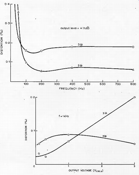
Fig. 9 Distortion of the compressor versus frequency for an input level of
+ 10 dB. Curves are substantially constant beyond 800Hz with a small increase
beginning beyond 10kHz.

Fig. 10 Distortion of the compressor versus output voltage level at a signal
frequency of 1kHz. There is a residua! distortion of about 0.05% third harmonic
in the oscillator which may alter the third harmonic results somewhat at low
levels.
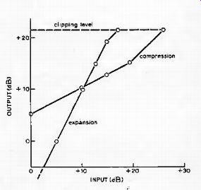
Fig. 11 Characteristics of the compander for high level signals.
Clipping level in the compression or the expansion mode is determined by the supply voltage of the operational amplifiers. Deviation from square-root compression and square-law expansion results from the current limiting of the amplifier A3 driving the LED These levels were obtained by setting the record and playback present potentiometers to 10kO. Altering these values will alter the point at which the behavior saturates.
Fig. 10 shows the second and third harmonic distortion versus the output signal level (the voltage across the photocell) at a frequency of 1kHz, Except at high output level, the distortion quickly falls near the noise limit of the wave analyzer. There is approximately 0.05% of residual third harmonic distortion in the oscillator which may slightly raise or lower the measured third harmonic, depending on phase relationships, Distortion level is low enough because it does not represent a crossover distortion, only a gently curving transfer characteristic. However, it would be unwise to be loo defensive about distortion levels in photocell circuits.
Some cells have much larger distortion than others, A number of different types were tried. I admit I could not hear the difference, but measured distortions of up to 2% at high level were occurring for some cells. The circuit whose measured low distortion is shown in Fig. 9 and 10 uses quite inexpensive cells, type VT-833, manufactured by Vactec Incorporated.* Any reasonably fast CdSe photocell could be used with resistance characteristics as described earlier. A quick check on distortion can be made by applying 10V r.m.s, at 1kHz to a divider made up of 10k-Ohm resistor and the ceil, illuminated to a resistance of about 10kO. If no appreciable curvature exists on an X-Y oscilloscope display or cell voltage versus oscillator voltage, the cell has suitable characteristics.
In Fig, 1F the clipping characteristics of the compander are shown in compression and expansion modes, The break point is due to current limiting of the amplifier A^ in Fig. 5 which drives the LED
[" U.K. agents Teknis Ltd, Teknis House, Meadrow, Godalming, Surrey GUT 3HQ. The pells cost around (mult. by 1.25 for USD ) £1, ]
The final test of performance of an audio circuit must be the human ear, In microphone arrangements using the compander there is dead quiet at no signal level. This is far from true without the compander. Replay sounds natural and the settings of the level controls on either recording or playback are unimportant as long as overload is prevented. Using good discs as a source there is no noticeable difference in the dynamics even on piano music when the compander is used.
This is impressive performance for such a simple circuit.
How can the audio enthusiast use the compander? If his tape recorder has a signal-to-noise ratio not much worse than the sources at his disposal, then it is hardly worthwhile using it to preserve dynamic range. However, modern stereo cassette recorders have signal-to-noise ratios of around 50dB, whereas a live FM broadcast can have 70dB. Then 20dB of increased dynamic range will result. In a live microphone setup with a low noise preamplifier the increase in dynamic range is greater than 40dB, and here the compander allows almost complete disregard of the level controls.
If master tapes and discs were made with a square root compressor and radio stations would broadcast these directly, then an expander in the receiver could bring back the full dynamic range of the original signal.
Another use for the compander occurs whenever there is a high background noise level, such as in an automobile, workshop, or a home with children. The unit can be used to process a signal using compress mode, so that the dynamic range of the signal stays sensibly above the noise level. It is wise to include the dotted resistor of Fig. 5 in such setups to reduce the noise output when the signal level is very low.
References
1 Burwen R. S. Design of a noise eliminator system Audio Eng. 5oc. Vol 19 December 1971.
2 Self, R. G. High-quality compressor printer, Wireless World, Dec. 1975 p. 587-90.
3 Stuart, J. R, Tape noise reduction, Wireless Worid March 1972,
4 Shorter, G. Wireless World Dolby noise reducer,: Wireless World, May 1975, p.200
5 Dolby f.m, broadcasting (letter), Wireless Worid, Sept 1974, p,344.
6 See, for example, Studio Sound, March 1974.