Point your TV aerial (antenna) at the nearest transmitter and switch on your set. Nine times out of ten the picture's perfect. Gordon King explains how the signal reaches your television and why, sometimes, it doesn't.
IF YOU ARE standing up in a small boat on the sea your distance from the visible horizon would be about 3 miles. If you are 200 feet up on a cliff the distance would be about 17 miles. It is a fundamental law of physics that light travels in straight lines (if it didn't we shouldn't be able to discern detail). Because the surface of the Earth is curved it follows that the greater our elevation, the farther we can see. The horizon distance in miles can be approximated by multiplying the height in feet by 1.5 and then finding the square root of the result.
Light is a part of the electromagnetic wave family, as are radio waves; but radio waves differ from light in that they have a longer wavelength. The wavelength of visible light ranges from about 0.00039mm (deep violet) to about 0.00064mm (deep red). After this comes infra-red and then radio waves from about 0.00077mm upwards to 6,000mm or more. 405-line TV occupies Bands I and III (Band II is used by FM radio) whose wavelengths respectively range from about 4.5 to 7.2 meters and 1.4 to 1.7 meters. 625-line TV (including colour of course) occupies Bands IV and V whose wavelengths respectively are about 516 to 628 mm and 351 to 483 mm. Band 1 embraces channels 1 to 5, Band III channels 6 to 13, Band IV channels 21 to 34 and Band V channels 39 to 68.
The speed at which light and radio waves travel is close to 300 meters each millionth of a second. The frequency of a wave of given length can thus be discovered merely by dividing 300 by the wavelength, the answer then being in millions (denoted by the capital M for mega) of cycles per second (denoted by Hz), or MHz.
The frequencies corresponding to the wavelengths of TV Bands I and III are called very high frequencies (VHF for short), while the frequencies corresponding to the wavelengths in Bands IV and V are called ultra high frequencies (UHF). VHF extends from 30 to 300 MHz and UHF from 300 to 3000 MHz. The wavelength of the vision signal of Channel 3 works out to 5.286m (56.75 MHz), that of Channel 10 1.5m (199.75 MHz), that of Channel 27 507mm (591.25 MHz) and that of Channel 52 417mm (719.25 MHz).

Fig. 1. Elementary impression of electromagnetic wave front advancing
out of the page, showing the alternating electric and magnetic fields
at right-angles to each other. The plane of polarization is in line with
the electric field, vertical in this illustration.
HOT ROCKS
We shall see in a subsequent feature that the size of the aerial conductors are related to the signal wavelength and hence the frequency. The exercise right now is to get some idea of how the TV signals are propagated through space; but before they can be dispatched into space they must first be generated. They commence life as fairly low power oscillations of accurately controlled frequency established by a quartz crystal enclosed in a constant-temperature oven. They are then passed through frequency multiplying and power amplifying stages to endow them with the required transmitting frequency and power, and ultimately matched to the transmitting aerial. At some stage during, these processes the information is modulated upon the radio-frequency ',RF) signal which, for the 625-line TV system, is amplitude modulation (AM) for vision and frequency modulation (FM) for sound.
The aerial (antenna) is tuned to the range of frequencies used by, the transmitter which is achieved by altering the dimensions of the conductors or slots of which the aerial is composed. When an RF signal is fed to an aerial which is correctly tuned and matched the signal is radiated into space in rather the same way as light is radiated from the top of a lighthouse, the main difference being that the radio waves are invisible.
In clear space and properly matched to the transmitter the aerial represents an impedance or resistance, which is called the radiation resistance. Signal current thus flows from the transmitter into the aerial and hence into space! Just how this happens is complex; but from a strictly elementary viewpoint the RF signal can be regarded as yielding self-supporting energy in space.
Part of the energy is electric and part magnetic. Hence the term electromagnetic wave. The electric and magnetic fields as they are called work at right-angles to each other, and if it were possible to see an electromagnetic wave advancing out of this page the two fields would be related as shown in Fig. 1.
The polarity of both fields changes continuously at a rate corresponding to the frequency of the signal, and it is the interaction of the changing polarities which keeps the signal going as a coherent whole as it travels at the speed of light through space. Radiation from an omni directional aerial (an aerial which is designed to radiate equally from all angles round it) takes the form of an expanding sphere of signal field of diminishing intensity, just as the intensity of light diminishes with distance.
For many TV purposes, however, both the transmitting and receiving aerials are designed for directionality, the first to concentrate he radiation in a specific direction or directions, and the second to discriminate against unwanted signals arriving from directions other than that of the wanted signal. The optical analogy is the reflector or lens. We shall see soon that TV signals can be reflected, refracted and diffracted just like light.

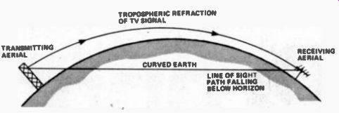
Fig. 2. Owing to tropospheric refraction, a TV signal is propagated
over a distance greater than the optical line-of-sight distance. There
is also a degree of diffraction of signal over the curves surfaces of
the Earth.

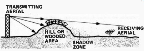
Fig. 3. A hill or heavily wooded area can obstruct UHF signals as shown.

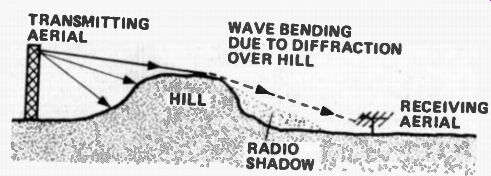
Fig. 4. It is sometimes possible to receive TV signals at the far side
of a hill owing to diffraction over the surface of the hill; but a shadow
zone is always present close to the foot of the hill.

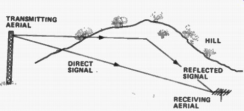
Fig. 5. Because a reflected TV signal has a longer path than the direct
signal it arrives a fraction of a second after the direct signal at the
receiving aerial and produces a ghost image on the screen as described
in the text.
TRANSVERSE ROPE TRICK
The direction of wave travel is perpendicular to the fields which are responsible for it; that is, the direction is at right-angles to the electric and magnetic fields. It is for this reason that an electromagnetic wave is called a transverse wave. An easily visualized transverse wave is that which is caused to run along a rope when one end is jerked sharply sideways. A distinction is a sound wave which is called a longitudinal wave because the molecules of the air or other medium through which it passes travel to and fro in a path which is parallel to the direction of propagation.
Under free-space conditions the signal intensity diminishes as the inverse square of the distance. This merely means that each time the distance is doubled the signal field falls by a factor of four. Under practical conditions, though, other factors come into play, such as topography, proximity of other aerials and buildings and tropospheric refraction. However, before looking at these things we should understand why it is that some TV aerials have their conductors or element vertically disposed while others have them horizontally disposed.
A radio Wave is said to have a specific polarization, vertical when the lines of electrical field are vertical (as in Fig. 1) and horizontal when the lines of electric field are horizontal. In order for a conductor type aerial to extract the maximum of energy from a passing radio wave it must be set up to correspond to the polarization of the wave. This is because the signal induced into the aerial results from the changing magnetic field cutting through the conductor (the dynamo principle). A slot aerial, on the other hand, needs to be set up in line with the magnetic field because such an aerial responds to the electric field. Some radio signals are slant polarized, notably the signals from some FM radio stations, so as to provide a reasonable response to both horizontal and vertical aerials, the latter which may be used with portable sets and car radios.
VHF and UHF signals, particularly the latter which are used for 625-line TV in Bands IV and V. are little affected by the ionosphere, which are 'electrified' or ionized layers surrounding the Earth, and thus pass straight through into outer space. To avoid this loss the radiation at high angles from TV transmitting aerials is deliberately curtailed. Long, medium and short wave signals, though, are considerably influenced by the ionosphere; they are reflected back to Earth by the layers which act rather like a large mirror in the sky, and for this reason are able to cover far greater distances than VHF and UHF signals, depending upon the time of day or night and the prevailing refractive index of the ionosphere.
The radiation of VHF and UHF signals from the top of a TV aerial is akin to the radiation of light from the top of a lighthouse. The waves travel in straight lines which means that the distance over which they may be received is significantly influenced by the respective--heights of the transmitting and receiving aerials. We have seen that for light the horizon distance in miles approximates the square root of 1.5 times the height in feet. The radio horizon distance for VHF and UHF signals is a little greater, approximating in miles the square root of 2 times the height in feet.
This is because the local layer of the Earth's atmosphere, called the troposphere, refracts the waves, causing them to curve slightly so that they hug the surface of the Earth over a greater distance than close to-Earth light rays. There is also a degree of diffraction over the surface of the Earth which further extends the distance.
Some TV transmitting aerials have an elevation of 1,000 feet, so from the top of such an aerial the radio horizon distance would be about 45 miles. If the receiving aerial has an elevation of 50 feet then this would have a radio horizon distance around 10 miles, giving a total radio distance between the tops of the two aerials of about 55 miles, as shown in Fig 2. At distances in excess of this the reception would start to deteriorate; it would be variable and inconsistent because the signal field at the receiving aerial would be relying on tropospheric conditions, which can change significantly with changes in air pressure and weather.
LOW PRESSURE TV
Enthusiasts interested in long-distance reception at VHF and UHF exploit abnormal tropospheric conditions.
When the tropospheric propagation deviates from the norm the radio distance increases owing to the change in refractive index of the troposphere, which is caused by temperature inversion effects (e.g., a change to in creasing temperature after a certain height). The signal then tends to be 'ducted' through the troposphere over quite considerable distances. This sort of propagation is more likely to happen during a spell of anti-cyclonic weather, especially where the pressure just starts to fall after a prolonged spell of high pressure and hence settled weather conditions. If you want to try your hand at receiving distant TV stations, keep your eye on the household barometer and tune over the TV bands at the start of a pressure decline following a high pressure period.
The very short wavelengths of visible light make it impossible for it to penetrate obstacles such as hills, buildings, walls, etc. in its path. The light thus casts a deep shadow behind the obstacle. Radio waves are more accommodating owing to their greater wavelengths.
However, with reducing wavelength, and hence in creasing frequency, radio waves tend to behave more and more like light rays. At the higher UHF channels even a wall can attenuate the signal arriving at the aerial if it is indoors. This is why it is always best to use a well elevated outside aerial for UHF television, especially at distances of 15 miles or more from a powerful station.
It is possible for a viewer to be located only a few miles from a high-channel UHF transmitter and yet be unable to obtain good reception from it. This can happen if a hill or wooded area obstructs the path between the transmitting and receiving aerials, as shown in Fig. 3. It may then be necessary to turn the aerial to a more distant transmitter, probably one with a lower channel number, to achieve reasonable reception. The screening effect of hills, etc. is less dramatic on the longer wavelength VHF channels because the far side of the hill may not be in total shadow owing to diffraction of the signal over the hill, as shown in Fig 4. However, if you are unhappily located close to the foot of the far side of a hill you could well be in a heavy shadow zone, even on the VHF channels, making it necessary to site the aerial at the top of the hill and feed signal down to the set through low-loss coaxial cable, probably via a preamplifier placed as close as possible to the aerial. There are quite a few viewers in hilly areas who need to do this.
Like light, VHF and UHF signals can also be reflected.
While a shiny surface or mirror is required for good reflection of light, any object which is large compared with the wavelength can reflect TV signals. This can be troublesome because the receiving aerial will respond first to the direct signal and then a fraction of a second later to the reflected signal. The reflected signal, of course, always takes a little longer to reach the aerial than the direct signal owing to its greater distance of travel, as shown in Fig 5.
DOUBLE VISION
If the path length of the reflected signal is, say, 1.5 km greater than the direct signal, the reflected signal will arrive at the aerial 5 s (5 millionths of a second) after the direct signal. This may not seem very significant; but it is because the scanning spot which traces out the picture on the TV screen takes only about 52ms (625-line system) to travel from left to right to make a full line.
Thus if the width of the screen is, say, 500mm the spot would have travelled 48mm when the reflected signal arrives. The result is a ghost display of the original image displaced by 48mm to the right.
Owing to the phasing of the reflected signal the ghost may appear in positive or negative form, and multiple ghosts result from multiple reflections. In severe cases the line synchronizing of the TV can be disturbed. The only real solution to this problem is to employ a highly directional aerial which can be orientated for maximum discrimination of the reflected signal or signals, as we, shall see in a later feature.
(adapted from: Hobby Electronics magazine, Mar. 1979)
Also see:
New Look For Communications Satellites