| Home | Sitemap/Articles |
AMAZON multi-meters discounts AMAZON oscilloscope discounts
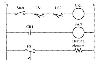
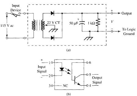
TRUE OR FALSE1. ______ The start switches LSI and LS2 in this figure are connected to form OR logic, since any of the three switches can turn on the control relay CR1. 2. _______ A relay with normally closed contacts will provide logic function that's similar to a NOT logic gate. 3. _______ An optoelectronic circuit like the one shown in this figure can provide isolation between two circuits. 4. _______ A solid-state relay can provide both the function of isolation and amplification. 5. _______ One advantage relays have over solid-state logic devices is that relays are faster acting. MULTIPLE CHOICE1. A typical relay has _______
2. A solid-state relay uses _______ to switch power.
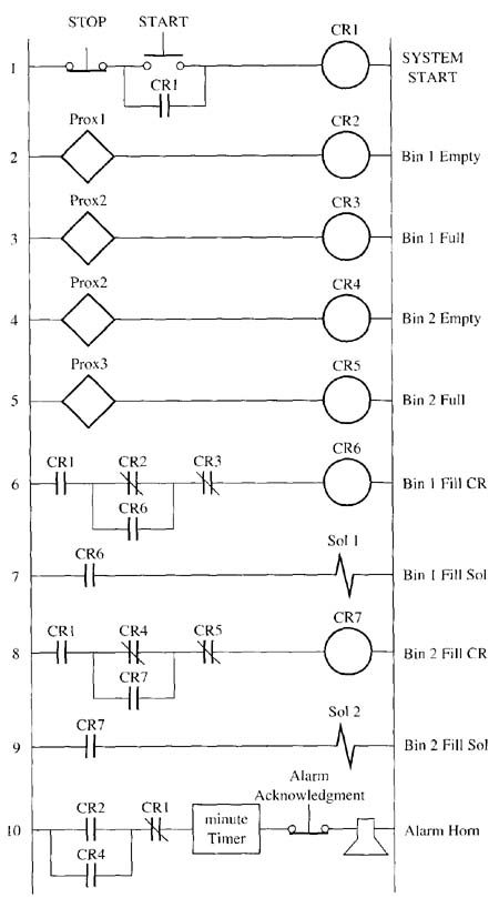
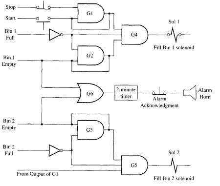
3. The Bin #1 Fill solenoid in line 7 of this ladder-logic diagram will be energized when CR1 is energized and ______.
4. The alarm horn in line 10 of this ladder-logic diagram will be activated when ______
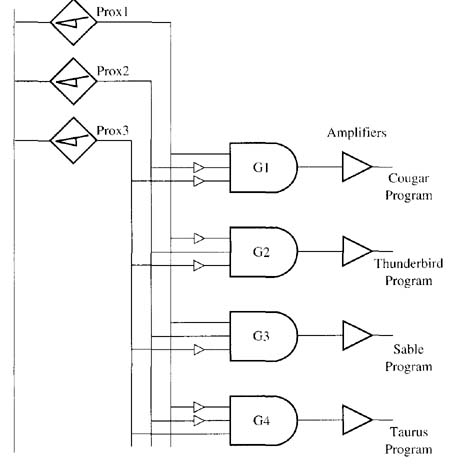
5. The Thunderbird program logic in this figure will be selected when ______
PROBLEMS1. Draw the symbol for and explain the operation of the basic logic gates: AND, OR, NOT, NAND, and NOR. 2. Draw or sketch the locations where you would place voltmeter leads in order to test the relay logic in this figure if the fill solenoid would not energize. 3. Draw or sketch a circuit that's used for signal conditioning or amplifying an output signal from a logic gate to make the signal interface a 110 volts ac relay coil. 4. Draw or sketch the relay contacts used to create the following gates: AND, OR, NOT, NAND, and NOR. 5. Draw a truth table for the operation of the bin level control circuits shown in this figure.
|
Thursday, January 18, 2024 11:04