| PREV: QUIZ | NEXT: |
AMAZON multi-meters discounts AMAZON oscilloscope discounts
You are assigned to convert a machine that operates with relay logic so that it will operate on solid-state gates. Your supervisor will provide the original ladder logic diagram of the machine for you. (See ill. 1 below.) When you have completed converting the machine to solid-state gates, you should turn on the power to the sys tem and test each input switch to determine that the output for the logic is correct. You should also be able to explain the parts of the circuit that may remain in control of relay logic where the relay provides an advantage over the solid-state gate. AMAZON multi-meters discounts AMAZON oscilloscope discounts |
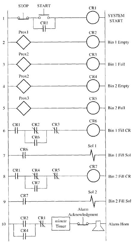
Above: Fig 1.
The solution to this job assignment should refer to the relay ladder-logic diagram shown in ill. 1 (above) and the solid-state logic circuit diagram shown in ill. 2 (below). This circuit is for the bin-level control system that controls the filling of the bin when it gets empty. Your solution should begin by identifying all the inputs in the relay logic and all of the conditions for the circuit. Each condition will be represented by a logic gate. If the relay logic contacts are in series, an AND gate will be used; if the relay contacts are in parallel, an OR gate should be used.
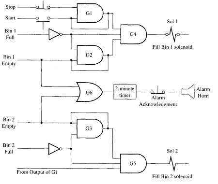
Above: Fig 2.
When you test the circuit, you should test each input with a logic probe to determine that its signal will go HI and LO. Next you should set all inputs to the proper signal to activate the logic. Test the output of the logic gate to determine that it has the proper signal. If you use any amplifiers or inverters, be sure to test them for the proper signal.
Refer to the table below to determine the strengths the relay provides that would better suit it for the job than the solid-state logic device. One reason to keep the relays is where amplification is required to get a small signal from the solid-state circuit to a level where it can energize or de-energize 110 volts ac devices.
Strengths of solid-state devices
Weaknesses of solid-state devices
Strengths of relays
Weaknesses of relays
|
| Top of Page | PREV: QUIZ | NEXT: |