| PREV: PLC -- Study Objectives | NEXT: |
The programmable controller has become the most powerful change to occur in the electronics world for factory automation. The programmable controller (P/C) is also called the programmable logic controller (PLC). Since the personal computer is called a PC, the programmable controller is referred to as a PLC to prevent confusion. As an electronics technician, you will run into the PLC in a number of places such as on the factory floor, in a repair facility, or you might work for a company that manufactures components and boards that are used to interface with PLCs.
| AMAZON multi-meters discounts AMAZON oscilloscope discounts |
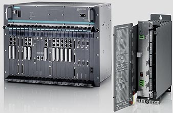
above: Siemens PLC
In this section you are going to study PLCs from two different perspectives. First, you will see how the PLC can be programmed to perform the same logic functions that the IC logic chips and relays in Sections 1 and 2 performed. Second, you will see the large amount of electronics involved in the input and output modules that the controller uses for interfacing a variety of industrial voltages. These modules contain a variety of electronic circuits to convert 110 volts and 220 volts AC signals to the low-voltage signals required in the PLC. From this information you will see that the PLC is as important to the industrial automation world as the personal computer is to the business world.
Today in industry you may find PLCs as stand-alone controls or as part of a complex computer integrated manufacturing (CIM) system. In these large integrated manufacturing systems the PLC will control individual machines or groups of machines. PLCs may also provide the interface between machines and robots, or machines and color graphics systems that are called man-machine interfaces (MMI).
In the 1970s and 1980s companies were able to hire both an electrician and an electronics technician to install, interface, program, and repair PLCs. Since the late 1980s the number of PLCs has grown so large that many companies have found that it's better to hire one individual with both electronic and electrical experience. This change will provide a large number of employment opportunities for electronics technicians who are willing to learn about industrial electrical applications such as the PLC. Other employment opportunities exist in companies that manufacture electronic boards and interface devices for PLCs. If you have never heard of a PLC or if you have had a minor introduction to them, this section will provide you with all of the information necessary to work successfully with them.
ill. 1: Typical programmable controllers.
A picture of typical types of PLCs is shown in ill. 1. This section will use generic PLC addresses where possible. When specific applications are provided, the Allen-Bradley SLC 100 and SLC 500 will be used as example systems. The early examples in this section will not be specific to any brand of PLC so that you may understand the functions that are generic to all controllers.
The computer part of the PLC, which is called a central processing unit (CPU), allows a program to be entered into its memory that will represent the logic functions. The program in the PLC is not a normal computer programming language like BASIC, Fortran, or C. Instead the PLC program uses contact and coil symbols to indicate which switches should control which outputs. These symbols look similar to a typical relay ladder diagram shown in Section 1. In most systems the program can be displayed on a computer screen where the actions of switches and outputs are animated as they turn motors and other outputs on or off. The animation includes highlighting the input and output symbols in the program when they are energized. Other systems use light-emitting diodes (LEDs) on a hand-held programmer that illuminate when an input or output is energized to show its status.
In short, the PLC executes logic programs like logic gates found on solid- state ICs, but its programs are designed to look exactly like relay ladder diagrams that electricians have used since earliest electrical controls were introduced. The PLC was designed to provide the technology of logic control with the simplicity of an electrical diagram so that its inputs and outputs are easy to troubleshoot. Since the logic is programmable, it's easily changed. The logic can also be easily stored on a disk so that it can be loaded into a PLC on the factory floor anytime the program logic for a controller needs to be changed as different parts are made or when the machine function needs to be changed.
When PLCs were first introduced, they allowed the factory electrician to use them to help troubleshoot large automated systems. As PLCs have evolved, they now provide many of the more complex logic functions such as timing, up/down counting, shift registers, and first-in, first-out (FIFO) functions.
ill. 2 shows an example of a PLC program. You should notice that the program looks exactly like an electrical relay diagram. As the program (diagram) gets larger, additional lines will be added. This gives the program the appearance of a wooden ladder that has multiple rungs. For this reason the program is called a ladder diagram, or it may be referred to as ladder logic.
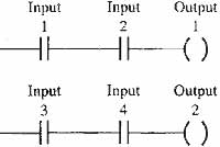
ill. 2: Example of a typical programmable controller program
called ladder logic. This program uses the generic addresses of
input 1, input 2, output 1, output 2, and so on.

above: The features of Hitachi's LADDER EDITOR for Windows help users program efficiently.
The original function of the PLC was to provide a substitute for the large number of electromechanical relays that were used in industrial control circuits in the 1960s. Early automation used large numbers of relays which were difficult to troubleshoot. The operation of the relays was slow and they were expensive to rewire when changes were needed in the control circuit. In 1969 the automotive industry designed a specification for a reprogrammable electronic controller that could replace the relays. This original PLC was actually a sequencer-type device that executed each line of the ladder diagram in a precise sequence. Later in the 1970s the PLC evolved into the microprocessor-type controller used today. Several major companies such as Allen-Bradley , Texas Instruments, and MODICON produced the earliest versions. These early PLCs allowed a program to be written and stored in memory, and when changes were required to the control circuit, changes were made to the program rather than changing the electrical wiring. It also became feasible for the first time to design one machine to do multiple tasks by simply changing the program in its controller.
Basic Parts of a Simple Programmable Controller
 All PLCs have four basic major parts: power supply, processor, input
modules, and output modules. A fifth part, a programming device, is not
considered a basic part since some PLCs will not have one if its program
is loaded from an EPROM (erasable programmable read-only memory) chip.
ill. 3 shows a block diagram of the typical PLC. From this diagram
you can see that input devices such as push button switches are wired
directly to the input module, and the motor starter or solenoids are
connected directly to the output module. Before the PLC was invented,
each switch would be directly connected to the motor starter or solenoid
it was controlling. In the PLC the switches and output devices are connected
to the modules, and the program in the PLC will determine which switch
will control which output. In this way, the physical electrical wiring
needs only to be connected one time during the installation process, and the control circuitry can be changed unlimited times through simple
changes to the ladder logic program.
All PLCs have four basic major parts: power supply, processor, input
modules, and output modules. A fifth part, a programming device, is not
considered a basic part since some PLCs will not have one if its program
is loaded from an EPROM (erasable programmable read-only memory) chip.
ill. 3 shows a block diagram of the typical PLC. From this diagram
you can see that input devices such as push button switches are wired
directly to the input module, and the motor starter or solenoids are
connected directly to the output module. Before the PLC was invented,
each switch would be directly connected to the motor starter or solenoid
it was controlling. In the PLC the switches and output devices are connected
to the modules, and the program in the PLC will determine which switch
will control which output. In this way, the physical electrical wiring
needs only to be connected one time during the installation process, and the control circuitry can be changed unlimited times through simple
changes to the ladder logic program.

The Programming Panel
At the bottom of the diagram in ill. 3 you can also see a programming panel. A progran device is necessary to program the PLC, but it's not considered to be one of the parts of a PLC because the programming panel or device can be disconnected after the program is loaded and the PLC will run by itself. The programming device is used so humans can make changes to the program, trouble shoot the inputs and outputs by viewing the status of contacts and coils to see if they are energized or dc-energized, and for saving programs to disk, or loading programs from disk.
The programming panel can be a dedicated device or it can be a personal or portable computer with PLC programming software loaded on it. The ladder logic program is able to be displayed on the programming device where it can become animated. This feature is unique to the PLC and it helps the technician troubleshoot very large logic circuits that control complex equipment. When a switch that's connected to the PLC input module is turned on, the program display can show this on the screen by highlighting the switch symbol everywhere it shows up in the program. The display can also highlight each output when it becomes energized by the ladder logic program. When the on/off state of a switch on the display is compared with the electrical state of the switch in the “real world,” a technician can quickly decide where the problem exists.
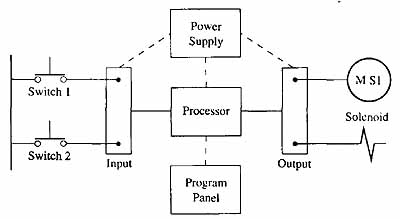
ill. 3: Block diagram showing the four major parts of a programmable
controller. The programming panel is the fifth part of the system, but
it's not considered a basic part of the PLC since it can be disconnected
when it's not needed.
Another feature that makes the PLC so desirable is the fact that it has most of the logic functions found in the machine language program of any microprocessor chip. This means that functions such as timing and counting can be executed by the PLC rather than using electromechanical or electronic timers and counters. The advantage to using timer and counter functions in the PLC is that they don't involve any electronic parts that could fail, and their preset times and counts are easily altered through changes in the program. Additional PLC instructions provide a complete set of mathematical functions as well as manipulation of variables in memory files. Modern PLCs such as Allen-Bradley PLC5 and Siemens T1545 have the computing power of many small mainframe computers as well as the ability to control several hundred inputs and outputs.
| Top of Page | PREV: PLC -- Study Objectives | NEXT: |