| PREV: Overview of Programmable Logic Controllers | NEXT: |
AMAZON multi-meters discounts AMAZON oscilloscope discounts
It may be easier to understand the operation of a PLC when you see it used in a simple application of sorting boxes according to height as they move along a conveyor. It is also important to understand that the addressing schemes for inputs and outputs of some PLCs may be difficult to understand when you are first exposed to them. For this reason the first examples of the PLC presented in this section will use generic numbering that does not represent any particular brand name. This will allow the basic functions of the PLC that are used by all brand-name of PLCs to be examined in a simplified manner. Later sections of this section will go into specific numbering systems for several major brands of PLCs.
AMAZON multi-meters discounts AMAZON oscilloscope discountsill. 4 shows a pictorial diagram as a top view of the conveyor sorting system. The locations of the photoelectric switches that detect the boxes and the pneumatic cylinders used to push the boxes off the conveyor are also shown in this diagram. Each air cylinder is controlled by a separate solenoid. The conveyor is powered by a three-phase electrical motor that's connected to a motor starter. Start and stop push buttons are used with the photoelectric switches to energize the coil of the motor starter that turns the conveyor motor on and off. ill. 5 shows all of the switches connected to an input module and solenoids and motor starter connected to an output module. The inputs are generically numbered input 1, input 2, and so on. The outputs are numbered output 10, output 11, and so on. The ladder logic program that determines the operation of the system is shown in ill. 6. The diagram of the switches and outputs connected to the input and output m uses the standard electrical symbol for each switch and output device.
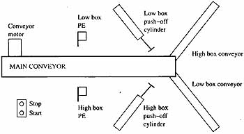
ill.4: Diagram of a conveyor sorting system that's controlled by
a generic programmable controller. Components: Low box; Low box push-off
cylinder; Conveyor motor; High box conveyor; MAIN CONVEYOR; Low box
conveyor; Stop/Start
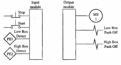
ill.5: Input and output diagram that shows all switches that are
connected to the PLC input module and motor starters that are connected
to the PLC output modules. The in put and output numbering is generic and does not represent any brand-name programmable controller.
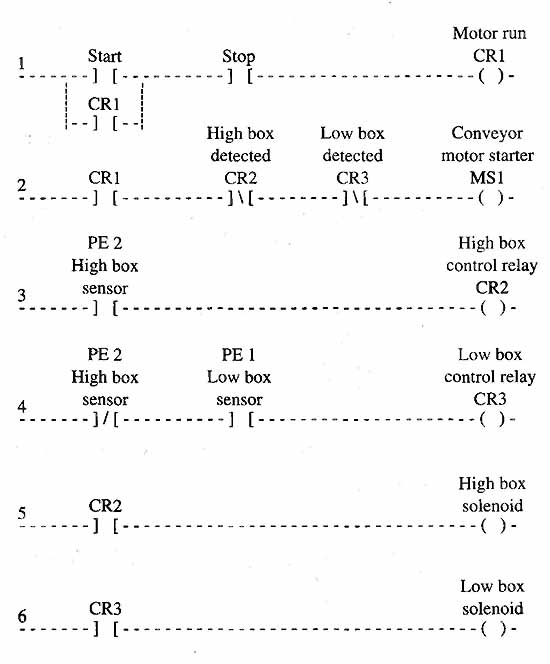
ill.6: Ladder logic diagram showing the logic control for the conveyor
sorting system. The diagram is generic and does not represent any particular
PLC brand.
In the ladder diagram notice that each switch is represented as a set of open contacts or closed contacts (--] [ or --] \ [--). Each motor starter or solenoid in the hardware diagram is represented by an output symbol --( )--. The numbers that are assigned to the switches, motor starters, and solenoids in the hardware diagram are used in the logic diagram so that you can determine which is being used.
Operation of the Conveyor Sorting SystemWhen the conveyor system is ready for operation, the start push button must be depressed. Since the stop push button is wired as an NC switch, power will pass through its contacts in the program to the start push-button contacts. When the start push button is depressed, the motor run condition will be satisfied in the first rung of the program and the motor run control relay in the program will be energized. The PLC can have hundreds of control relays in its program. The advantage of having control relays in a PLC program is that they provide the logic functions of a control relay, which can have multiple sets of NO and NC contacts, yet they only exist inside the PLC so they can never fail or break. A set of NO contacts from CR1 is connected in parallel with the start push button to seal it in because the start push button is only momentarily closed. The photoelectric switches are used to energize and dc-energize the conveyor motor starter in the second line of the logic. Line 2 of the diagram is designed so the start/stop circuit can turn the motor starter on or off without affecting the start/stop circuit. The photoelectric switches send out a beam of light that's focused on a reflector mounted on the opposite side of the conveyor. As long as a box does not interrupt the beam of light, the photoelectric switches will be energized. When the motor run control relay coil (CR1) in the first rung of the program is energized, its NO contacts in the second rung of the program will become “logically” closed. Since no boxes are being sensed by the photoelectric switches, they will be energized and their contacts in the program, low box PE and high box PE, will pass power to the output in the second rung called motor starter. This directly controls the coil of motor starter 1. When motor starter 1 is energized, the conveyor motor is energized and the conveyor belt begins to move. As boxes are placed on the conveyor, they will travel past the photoelectric switches. If the box is a low box, photoelectric switch PE1, which is mounted to detect the low box, will become energized. This will cause three things to happen. First, the NO contacts of PE1 low box sensor in rung 4 will close. Since the box is not a high box, the NC contacts of PE2 high box sensor in rung 4 will remain closed to pass power to PE1 low box sensor contacts (that are now closed) and on to the coil of CR3 (low box control relay). Second, the coil of CR3 is energized and all of the contacts in the program that are identified as CR3 will change state. This means the NC CR3 contacts in rung 2 will open and de-energize MS1, the conveyor motor starter. When MS1 is dc-energized, the motor starter will become de-energized and the conveyor motor will stop. Third, when the coil of CR3 is energized by PE1 low box sensor, the output for the low box solenoid is energized and the rod of the low box push-off cylinder is extended. The low box is pushed off the main conveyor onto the low box conveyor. After the low box is pushed off the main conveyor, it will no longer activate PE1, and the coil of CR3 will become dc-energized in rung 3. When the coil of CR3 is dc-energized, the NC CR3 contacts in rung 2 will return to their closed state, which will energize the output for MS1 and start the conveyor motor again. When a high box moves into position on the conveyor, it will block both the high box photoelectric switch PE2 and the low box photoelectric switch PE1. This could create a problem of having both the low box control relay CR3 and the high box control relay CR2 energized at the same time if it were not for the logic in rung 4 that's specifically designed to prevent this. Since the contacts of the high box sensor PE2 are programmed normally closed in rung 4, they will open when the high box is detected and not allow power to pass to the coil of CR3. This type of logic is called an exclusion, since it prevents both control relay coils from energizing at the same time even though both photoelectric switches are activated by the high box. When the high box is detected by PE2, the NC PE2 contacts in rung 3 will close and energize the coil of the high box control relay CR2. When the coil of CR2 is energized, all of the contacts in the program that are identified as CR2 will change state. The NC CR2 contacts in rung 2 will open and de-energize the coil of MS1, the conveyor motor starter. The NO CR2 contacts in rung 5 will close at this time and energize the high box solenoid and air will be directed to the high box pneumatic cylinder. Then the high box will be pushed off the conveyor. After the box has been pushed off the conveyor, the photoelectric switch that detected the high box will return to its normal state, and high box contacts in rung 2 will return to their normally closed logic state. The motor starter will become energized again and start the conveyor motor. The high box contacts in rung 3 will return to their normally open logic state and the push-off cylinder will be retracted. This allows the conveyor to return to its normal operating condition. |
| Top of Page | PREV: Overview of Programmable Logic Controllers | NEXT: |