| PREV: Inputs and Outputs for the Carbon Brush Process System | NEXT: Using Timers to Stage the Electric Heat |
AMAZON multi-meters discounts AMAZON oscilloscope discounts
Since the heat-treating part of the brush-making system consists of simple switches and outputs, we will begin our discussion at this point. The first three rungs of the program show examples of NO (examine on) contacts and NC (examine off) contacts. The first line of the logic shows a traditional start/stop circuit. The start button is connected to input address 001 so all of the contacts in the program that are numbered 001 will represent the start push button. The stop push button is connected to address 002. You should notice from the I/O diagram in ill. 16a below that the start push button is wired as a set of NO push button contacts, and the stop push button is wired as a set of NC contacts.
AMAZON multi-meters discounts AMAZON oscilloscope discounts 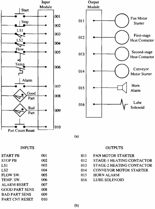
ill.16 (a): Diagram showing the symbol and address for each input and output for the brush manufacturing mixing and heat-treating system.
(b) List of input switches and output devices for the mixing and heat-treating
system.
When the operator is ready to start the machine, the start push button will be depressed. You will notice in the ladder diagram that both the start and stop switches use NO contacts. The stop push button that's hard wired to the input module must use NC contacts as a fail-safe condition. This means that the switch will stop the system if the switch becomes faulty or if one of the wires connected to the switch comes loose from its terminals. Since the real stop switch uses NC contacts, its programmed contacts must be normally open for the circuit to operate correctly. At first glance this seems contradictory, but since the stop push-button contacts are held closed by a spring, they will send a signal to the input module at all times unless the push button is depressed. This means the NO contacts (002) in the program will change state and pass power to the start push-button contacts (001) as long as the contacts in the hardware part of the stop push button remain closed. Since contacts 002 (stop push button) will continually pass power, output 017 in line 1 will become energized as soon as the start push button is depressed.
You should also notice in rung 1 that the 001 start contacts have a set of NO 017 contacts connected in parallel with them. The parallel contacts have the number 017, which means they are controlled by the output 017. These contacts will act as a seal-in circuit around the start contacts. When the start push button is depressed, its hardware contacts are closed momentarily. Then when the operator’s finger is removed from the button, the contacts will open again because of the spring pressure. Since the programmed start contacts 001 will only be closed momentarily, the output would become dc-energized as soon as the start button is released. The seal-in contacts from output 017 will provide an alternate path around the start contacts. Anytime the stop push button is depressed, its contacts 002 will open and de energize output 017.
Output 017 has been chosen as the output in this rung because it's an internal relay. Since this rung represents the permissive start-circuit condition, it means that output 017 does not need to be connected directly to an output module address, since it will not provide power directly to any of the output devices. A second set of 017 NO contacts is used in rung 2 with two door limit switches to provide a signal to energize the fan motor starter coil. If both doors on the oven in the heat- treating section are closed, their limit switches will pass power and the fan motor starter will be energized as soon as the start/stop permissive circuit (output 017) becomes energized. If either of the doors are opened while the oven is in use, the limit switch for the door will open and dc-energize the motor starter. Since the limit switches are in rung 2, their operation will not affect the start/stop circuit in rung 1.
The start/stop permissive contacts (017) are also used to energize the coil for the conveyor motor starter (014) in rung 7. The motor starter for the conveyor motor can be dc-energized by the set of NC 006 contacts from the temperature switch which will open anytime the temperature exceeds 180°F, or by depressing the stop push button, which will dc-energize the 017 permissive contacts.
Using Latch and Unlatch Coils Rungs 8 and 9 use a special type of coil to ensure that an alarm
light and horn are energized any time the temperature exceeds 180°F.
The temperature switch 006 is used to activate the alarm. A problem
could arise if the temperature returns to a safe value before the
operator determines that a problem has occurred. The latch coil
-(L)- 015 in rung 8 will operate like a flip-flop in that it will
remain energized even if contacts 006 become dc-energized. The
alarm light and horn will remain energized until the unlatch coil
015 in rung 9 is energized. The operator must depress the alarm
acknowledge button 007 and the NC 006 contacts in rung 9 must be
closed to indicate the temperature is below 180°F. The latch and unlatch coils must both have the same address number to operate
as a pair. |
| Top of Page | PREV: Inputs and Outputs for the Carbon Brush Process System | NEXT: Using Timers to Stage the Electric Heat |