| PREV: Using the SLC 100 to Control a Batch and Heat-Treating Process: Making Carbon Brushes | NEXT: Operation of the Heat-Treating Part of the System |
AMAZON multi-meters discounts AMAZON oscilloscope discounts
The PLC program is shown in ill. 14. The controls for the carbon brush system have nine input switches connected to the input module and six devices connected to the output module of the SLC 100 PLC. The input/output (I/O) diagram in ill. 16 below shows these components connected to their respective input and output modules. You should also notice that the address for each device is provided. The I/O diagram will also show the electronic symbol for each switch and it will show if the switch contacts are wired normally open or normally closed. You will need to refer to the PLC program and the I/O diagram as the different parts of the machine are explained.
AMAZON multi-meters discounts AMAZON oscilloscope discounts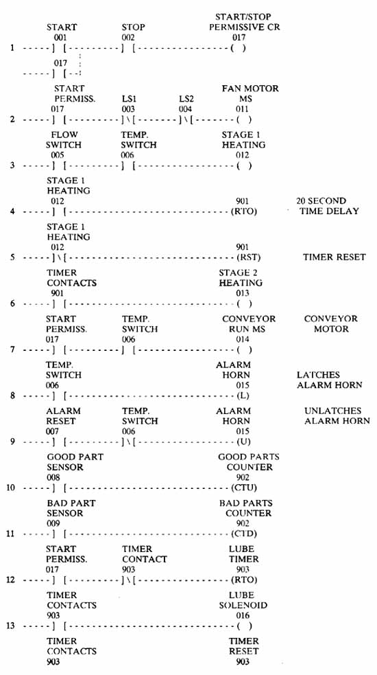
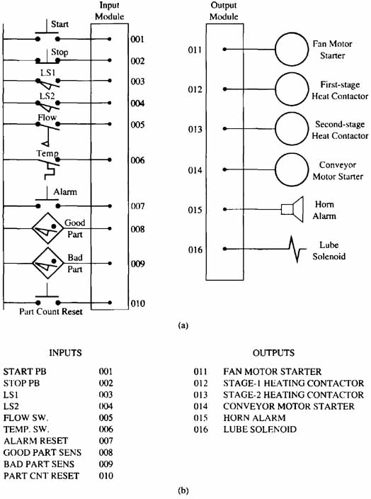
ill.16: (a): Diagram showing the symbol and address for each input and output for the brush manufacturing mixing and heat-treating system.
(b) List of input switches and output devices for the mixing and heat-treating
system.
| Top of Page | PREV: Using the SLC 100 to Control a Batch and Heat-Treating Process: Making Carbon Brushes | NEXT: Operation of the Heat-Treating Part of the System |