| PREV: An Example of a Programmable Controller Application | NEXT: |
AMAZON multi-meters discounts AMAZON oscilloscope discounts
The PLC processor examines its program line by line, which is the way it solves its logic. The processor in the PLC actually performs several additional functions when it's in the run mode. These functions include reading the status of all inputs, solving logic, and writing the results of the logic to the outputs. When the processor is performing all of these functions, it's said to be scanning its program. ill. 7 below shows an example of the program scan.
AMAZON multi-meters discounts AMAZON oscilloscope discounts 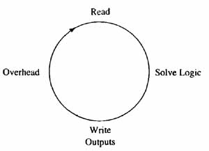
ill.7: Example of a typical programmable controller scan. The processor
continually reads the status of all inputs, solves logic, and writes
the results of the logic to all out puts. The fourth part of the scan
cycle is called overhead and it includes the functions of communications
with the programming panel, printer, color screens, and so on.
The PLC provides a means to determine when the switches that are connected to its input module are energized or de-energized. When the contacts of a switch are closed, they allow voltage to be sent to the input module circuit. The electronic circuit in the input module uses a light-emitting diode and a phototransistor to take the 110 volts ac signal and reduce it to the small-voltage signal used by the processor.
The contacts in the program that represent the switch will change state in the program when the module receives power. If you use the programming panel to examine the contacts in the PLC program, they will highlight when the switch they represent is energized. The PLC will transition the state of the programmed contacts at this time. E.g., if the contacts are programmed normally open, when the real switch closes and the module is energized, the PLC will cause the programmed contact to transition from open to closed. This means that the programmed contacts will appear to pass power through them to the next set of contacts. If both sets of contacts are passing power in line 1 of the program, the output will become energized.
AMAZON multi-meters discounts AMAZON oscilloscope discountsImage Registers
One of the least understood parts of the PLC is the image register. The image register is a memory section that's specifically designed to keep track of the status (on or off) of each input. This means that the image register is 1 bit wide. ill. 8 shows an example of the image register. From this diagram you can see that all of the inputs and outputs for the PLC each have one memory location where the processor will place a 1 or 0 to indicate whether the input or output connected to that address is energized or de-energized. The processor determines the status of all inputs during each scan cycle by checking each one to determine if the switch connected to it's energized. If the switch is energized and the input module sends a signal to the processor, the processor will place a binary 1 in the memory location in the image register that represents that input. If the switch is off, the processor will place a binary 0 in the memory location for the image register. This means the image register will have an exact copy of the status of all its inputs during the read part of the scan. Some PLCs also call the image register the image table.
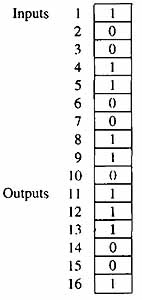
ill.8: Example of an image register for a PLC. The image
register is 1 bit wide and has a memory location for each input and output in the PLC.
In the second part of the PLC scan the processor uses the values in the image register to solve the logic for that particular rung of logic. E.g., if input 1 is ANDed with input 2 to turn on output 12, the processor looks at the image register address for input 1 and input 2 and solves the AND logic. If both switches are high, and a 1 is stored in each of the image register addresses, the processor will solve the logic and determine that output 12 should be energized.
After the processor solves the logic and determines the output that should be energized, the processor will move to the third part of the scan cycle and write a 1 in the image register address for output 12. This is called the write cycle of the processor scan. When the image register address for output 12 receives the 1, it immediately sends a signal to the output module address. This energizes the electronic circuit in the output module, which sends power to the device such as the motor starter that's connected to it.
It is important to understand that the PLC processor updates all of the addresses in the image register during the read cycle even if only one or two switch addresses are used in the program. When the processor is in the solve logic part of the scan, it will solve the logic of each rung of the program from left to right. This means that if a line of logic has several contacts that are ANDed with several more contacts that are connected in an OR condition, each of these logic functions is solved as the processor looks at the logic in the line from left to right. The processor also solves each line of logic in the program from top to bottom. This means that the results of logic in the first rung are determined before the processor moves down to solve the logic on the second rung. Since the processor continues the logic scan on a continual basis approximately every 20-40 msec, each line of logic will appear to be solved at the same time.
The only time the order of solving the logic becomes important is when the contacts from a control relay in line 1 are used to energize an output in line 2. In this case the processor will actually take two complete scan cycles to read the switch in line 1 and then write the output in line 2. In the first scan, the processor will read the image register and determine the start push button has closed. When the logic for rung 1 is solved, the control relay will be energized. The processor will not detect the change in the control relay contacts in the second line until the second scan when it reads the image register again. The output in the second line will finally be energized during the write cycle of the second scan and power will be sent to the motor starter coil that's connected to the output address. It is also important to understand that the processor will write the condition of every output in the processor during the write part of the scan even if there is only one or two outputs used in the program.
The image register is also useful to the troubleshooting technician, since the contents of each address can be displayed on a CRT. The technician can compare the image register with the input and output modules and the actual switches and solenoids that are hard wired to the modules.
A separate image register is also maintained in the processor for the control relays. In some systems these relays are called memory coils or internal coils. A control relay has one coil and one or more sets of contacts that can be programmed normally open or normally closed. When the coil of a control relay is energized, all of the contacts for the relay will change state. Since control relays reside only in the program of the PLC and don't use any hardware, they can't have problems such as dirty contacts or an open circuit in their coil. This means that if the contacts of a control relay will not change from open to closed, you would not suspect the coil of having a malfunction. Instead you would look at the contacts that control power to the control relay coil in program, and one or more of them will be open, which causes the coil to remain de-energized.
When the processor is in the run mode, it updates its input, output, and control relay image registers during the write-I/O part of every scan cycle. Since the image registers are continually updated approximately every 20-40 msec, it's possible to send copies of them to printers or color graphic terminals at any time to indicate the status of critical switches for the machine process. This allows the machine operator to do minor troubleshooting when a problem occurs before a technician is called. E.g., if an operator is running a press or machine that must have a door or gate closed before it will begin its cycle, a fault monitor on a color graphic display can show the status of the door switch. If the door becomes ajar and the cycle will not start, the operator can look at the fault monitor and the copy of the input image register from the PLC would indicate that the door switch was open. The operator could take the appropriate action instead of calling a technician. In this manner, the PLC not only controls the machine operation, but it also helps in troubleshooting.The Run Mode and the Program Mode
When the PLC is in the run mode, it's continually executing its scan cycle. This means that it monitors its inputs, solves its logic, and updates its outputs. When the PLC is in the program mode, it does not execute its scan cycle. The name program mode was originally used because older PLCs could not have their programming changed while executing their scan cycle. Modern PLCs have the ability to have their program edited and changed while the processor is in the run mode. At first glance, changing the PLC program while it's in the run mode looks dangerous, especially when the machine the PLC is controlling is in automatic operation. But you will find in larger control applications like pouring glass continually or continuous steel rolling mills, it's not practical to stop the machine process to make minor program changes. In these types of applications the changes are made while the PLC is in the run mode. As a rule, you should switch the PLC to the program mode if possible when any program changes are being made.
On-Line and Off-Line Programming
The programming software for a PLC may allow you to write the ladder logic program in a personal computer and later download the program from the personal computer to the PLC. If you are connected directly to a PLC and you are writing the ladder logic program in the PLC memory, it's called on-line programming. If you are writing the ladder logic program in a personal computer or programming panel that's not connected to a PLC, it's called off-line programming. Most modern PLC programming software allows the program to be written on a personal computer without being connected to the PLC. This allows new programs or pro gram changes to be written at a location away from the PLC. E.g., you may write a program in Detroit , save the changes on a floppy disk, and mail the disk to Chicago where the PLC is connected to automated machinery. If you are using a hand-held programmer, it must be connected directly to a PLC so that you are writing the program in the PLC memory. It is also important to understand that some small PLCs like the Allen-Bradley SLC 100 don't have a microprocessor chip, so you can't write the PLC program on line. Since the SLC 100 does not have a microprocessor chip, all programming must be completed off line, and then you must download the program changes to the PLC memory.
| Top of Page | PREV: An Example of a Programmable Controller Application | NEXT: |