| PREV: Scanning a PLC Program When it's in The Run Mode | NEXT: |
AMAZON multi-meters discounts AMAZON oscilloscope discounts
It may be easier to equate the operation of a PLC controlled program with the same program using solid-state logic (AND, OR, and NOT) functions. ill. 9 shows a diagram of the conveyor box sorting system using solid-state logic functions. You can see that the start and stop push buttons are inputs to the first AND gate (G1). The output of G1 is sent to the three-input AND gate (G2) along with the inverted signal from the high box photoelectric switch and low box photoelectric switch. The output of G2 is sent to the motor starter coil. AND gate (G3) is used to determine that the box is a low box by using a normal input from low box PE and an inverted input from high box PE. The output of G3 is used to energize the low box push-off solenoid. The high box PE signal is also used to energize the high box push-off solenoid.
AMAZON multi-meters discounts AMAZON oscilloscope discounts 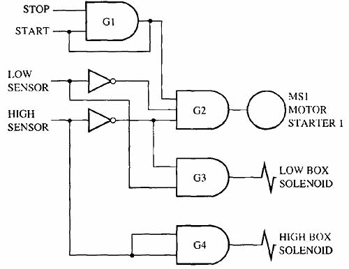
ill.7: Solid- state logic gates used to provide the same logic as
the PLC box sorting program.
As you know, the input switches must be sent through a signal conditioner because they are powered by 110 volts ac and they interface with the low-voltage logic chips. The outputs must also be sent to a signal conditioner (amplifier) to increase the low voltage logic output signal to 110 volts ac to be usable to energize the motor starter and solenoids. The input and output modules of the PLC provide the same function of the signal conditioners and amplifiers in the solid-state logic circuit.
| Top of Page | PREV: Scanning a PLC Program When it's in The Run Mode | NEXT: |