| PREV: Equating the PLC with Traditional Solid-State Logic | NEXT: |
AMAZON multi-meters discounts AMAZON oscilloscope discounts
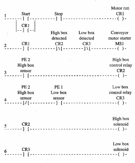
The examples in ills. 4 , 5 and 6 show several unique features of the PLC. First, notice that the ladder diagram allows you to analyze the program in the sequence that it will occur. Second, the PLC allows you to program more than one set of contacts in the program for each switch. E.g., the photoelectric switch may be in the program both normally open and normally closed as many times as the logic requires. The PLC gives you the capability of solving AND, OR, and NOT logic by connecting contacts in series and parallel, and using NO and NC contacts. ill. 10 below shows examples of the five basic logic circuits as you would see them in ladder logic. As complex as some ladder logic programs look, you must remember that the logic program can only consist of combinations of these five basic functions.
AMAZON multi-meters discounts AMAZON oscilloscope discounts 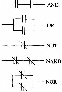
ill.10: Five basic ways to program contacts in a PLC: in
series (AND), in parallel (OR), normally closed contacts (NOT), series
normally closed contacts (NAND), and parallel normally closed contacts
(NOR).
Another feature of the PLC is the control relay or internal coils or memory relays. The relay has one coil and it can have any number of NO or NC contacts. When the coil is activated, all the contacts in the program that have the same address number as the coil will change state. The control relay exists only inside the PLC, which means it can never break or malfunction physically. Also since control relays exist only in the PLC memory, you can have as many of them as the memory size can accommodate. This means you can add control relays to accommodate changes to the machine control logic as long as the PLC has space remaining in its memory.
AMAZON multi-meters discounts AMAZON oscilloscope discountsIt may help to see a case where a control relay is used in an actual circuit. E.g., in ill. 6, you can see control relay (CR3) is used to indicate the logic has determined that a low box has been detected. The control relay in this rung of the program does nothing more than represent the conditions that indicate a low box has been detected. These conditions consist of the low box PE1 being on and the high box PE2 being off. Anytime CR3 is energized, a low box has been detected, and it will change the state of its contacts throughout the remainder of the program to represent the low box has been detected.
In many cases each control relay in a program represents a condition for the machine operation, such as “ready to go to auto,” “all safety doors closed,” or “ready to jog.” If you think of the condition the control relay represents each time you see the control relay contacts, you will find it easier to read and interpret the program.
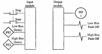
Another feature of the PLC that makes complex factory automation easier to troubleshoot is the way that each input switch or each output load is electrically connected to its interface module. In ill. 5 you can see that when a switch is connected to an input module only two wires are involved. The outputs also use only two wires to connect the load device like the coil of a motor starter to the module. This means that when there is a malfunction in the electrical part of the circuit, the troubleshooter only has the switch and two wires to check for any individual input and the coil and two wires for any output. When you compare this type of wiring to a complex series-parallel circuit in an older-style relay panel, you can see it's much easier to troubleshoot two wires and a switch, or two wires and a solenoid. In the older-style relay panels a typical signal may pass through 10 to 15 relay contacts and switches and all the wiring that connects them together before it gets to a solenoid. This means that an open could occur in this complex circuit when any set of contacts opens, any switch opens, or if a wire has a fault where it becomes open.
To make troubleshooting the switch and two wires that connect it to an input module even easier, a small indicator light called a status indicator is connected to each input circuit. It is mounted on the face of the module so it's easy to see. The troubleshooter can look at the status indicator and quickly determine if power is passing through the contacts or not. If the switch contacts are closed but the status indicator is not illuminated, the troubleshooter needs to check only the two wires and the switch for that circuit to see where the problem is. This feature is particularly valuable when the automated system the PLC is controlling has several hundred switches that could cause a problem. A status indicator is also connected to each output circuit and mounted on the face of the output module. Anytime the PLC energizes an output, the status indicator for that circuit will be illuminated.
Classifications of ProgrammableControllers PLCs are generally classified by size. The small-sized system costs from $500 to $1000 and has room for a limited number of inputs and outputs. As a general rule, the small PLCs have less than 100 inputs and outputs with approximately 20 inputs and 12 outputs mounted locally with the processor. Additional inputs and outputs can be added through remote I/O racks to accommodate the remaining inputs and outputs. These PLCs generally have 2K to 10K of memory that can be used to store the user’s logic program.
The advent of local area networks brought about the concept known as distributive control, where small and medium size PLCs are connected together through the network. In this way, the entire factory is brought under the control of a number of PLCs, but a failure in one system will not disturb any other system. The sizes of the majority of PLCs that you will encounter today will be small and medium systems that are used as stand-alone controls or as part of a network. |
 Medium-sized PLCs cost
from $1000 to $3000 and have extended instruction sets that include
math functions, file functions, and PID process control. These
PLCs are capable of having up to 4000 to 8000 inputs and outputs.
They also support a wide variety of specialty modules such as
ASCII communication modules, BASIC programming modules, 16-bit
multiplexing modules, analog input and output modules that allow
interfaces to both analog voltages and currents, and communication
modules or ports that allow the PLC to be connected to a local
area network (LAN). Large-sized PLCs were very popular in the early
1980s before networks were perfected. The concept for the large-sized
PLC was to provide enough user memory and input and output modules
to control a complete factory. Problems occurred when minor failures
in the system brought the complete factory to a halt.
Medium-sized PLCs cost
from $1000 to $3000 and have extended instruction sets that include
math functions, file functions, and PID process control. These
PLCs are capable of having up to 4000 to 8000 inputs and outputs.
They also support a wide variety of specialty modules such as
ASCII communication modules, BASIC programming modules, 16-bit
multiplexing modules, analog input and output modules that allow
interfaces to both analog voltages and currents, and communication
modules or ports that allow the PLC to be connected to a local
area network (LAN). Large-sized PLCs were very popular in the early
1980s before networks were perfected. The concept for the large-sized
PLC was to provide enough user memory and input and output modules
to control a complete factory. Problems occurred when minor failures
in the system brought the complete factory to a halt. 
| Top of Page | PREV: Equating the PLC with Traditional Solid-State Logic | NEXT: |