| PREV: Operation of Programmable Controllers | NEXT: Example Input and Output Instructions for the SLC 100 |
AMAZON multi-meters discounts AMAZON oscilloscope discounts
Up to this point in our discussion we have identified inputs and outputs in generic terms. In reality the processor must keep track of each input and output by an address or number. Each brand-name PLC has devised its own numbering and addressing schemes, which generally fall into one of two categories: sequentially numbering each input and output, or numbering according to location of input and output modules in the rack. The sequential numbering system is used in most small- sized PLCs and about half of the medium-sized systems. Allen-Bradley, one of the most popular brands, uses two different addressing systems. In its medium-sized PLCs (PLC2 and PLC5) the address for an input or output uses numbers that indicate the location of the input or output module in the rack, and it uses a sequential numbering system for addresses in its small-sized SLC 100 PLCs.
AMAZON multi-meters discounts AMAZON oscilloscope discountsFrom this point on, the applications will use the address and numbering scheme of the Allen-Bradley SLC 100. If you are using a different brand-name PLC, you will need to convert the addresses to your system if you wish to try the program examples. ill. 12 shows an example of the numbering system used in the Allen- Bradley SLC 100 small-sized PLC. (The SLC 150 is a similar system that's a little larger in that it has a combination of 32 inputs/outputs (I/O’s) directly attached to its processor, while the SLC 100 has a combination of 16 inputs / outputs attached to its processor.) From this example you can see that for the SLC 100 the input addresses start with address 001 and continue through address 010. Output addresses start with address 011 and continue through address 016. The first group of I/O is mounted locally on the processor. It is very important to understand that each I/O point address refers to a specific circuit in the hardware module and to a specific address in the processor’s memory. The addresses in memory are assigned to memory blocks. The diagram that displays all of the addresses in a memory block is called a memory map.
AMAZON multi-meters discounts AMAZON oscilloscope discounts 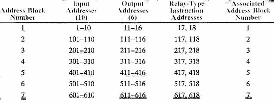
ill.12: Input and output addresses for the Allen-Bradley SLC 100.
Address Block Number; Input and Output Addresses.
| If expansion modules are added to the processor, the first one would have input addresses 101 - 110 and output addresses 111 - 116. Up to six expansion modules can be added to the system so that the highest input addresses would be 601- 610 and the highest output addresses would be 611 - 616. This figure also shows the addresses of internal relays. As you know, the internal relays act like a control relay in that both perform logic but don't directly energize an output. From the figure you can see the internal relays are numbered 17 and 18 in the first block and 117 and 118 in the next block. If six additional expansion modules are used, the addresses can go to 617 and 618. |
| Top of Page | PREV: Operation of Programmable Controllers | NEXT: Example Input and Output Instructions for the SLC 100 |