| PREV: Addresses for Inputs and Outputs for the SLC 100 | NEXT: Using the SLC 100 to Control a Batch and Heat-Treating Process: Making Carbon Brushes |
AMAZON multi-meters discounts AMAZON oscilloscope discounts
ill. 13 below shows an example of all of the input and output instructions the SLC 100 uses. From this figure you can see that normally open and normally closed contacts are provided for input instructions. The SLC 100 uses the name examine on for the NO contacts --] [-- and examine off for the NC contacts --] \ [--. The term examine was chosen to remind you that the processor looks at (examines) the electronic circuit in the input module to see if it's energized or de-energized. The processor will keep track of the status of the circuit by placing a 1 in the image register address if it's energized and a 0 if it's de-energized. The word examine is also used to remind you to look at the status light on the front of the module so that you can also determine if the input circuit is energized or de-energized. The branch instructions are used to allow contacts to be connected in parallel to each other in the ladder diagram.
AMAZON multi-meters discounts AMAZON oscilloscope discounts 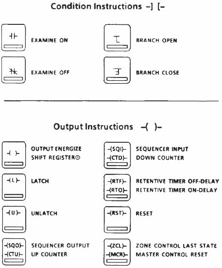
ill.13: Example in put and output instructions available in the Allen-Bradley SLC 100.
Instruction set of the SIC controller. Symbols are representations of the pocket
programmer keys. The Shift Register symbol is -(SR)-. It does not appear on the
programmer key.
The output instruction in this figure includes the traditional coil, which uses the symbol -( )-. This instruction is named output energize. Specialized outputs called the latch --(L)-- and the unlatch --(U)-- are also provided. The latch and unlatch coils act similarly to the flip-flops discussed in earlier. The latch output will maintain its energized state after it's energized by an input even if the input condition becomes de-energized. The unlatch output must be energized to toggle the output back to its reset (off) state. The latch coil and unlatch coil must have the same address to operate as a pair.
Latch coils are used in industrial applications where a condition should be maintained even after the input that energized the coil returns to its de-energized state. It is important to understand that the latch coil bit will remain HI even if power to the system goes off and comes back on. This feature is important in several applications such as fault detection. Many times a system has a fault such as an over-temperature or overcurrent condition. After the fault is detected, the machine is automatically shut down by the logic and by the time the technician or operator gets to the machine, the condition is back to near normal and it's difficult to determine why the system shut down. If a latch coil is used in the detection logic, the fault bit will remain HI until the fault reset switch energizes the un latch instruction.
Another application for the latch coil is for feed water pumps or fans that are located in remote locations in the building such as in the ceiling. A latch coil is used in these circuits because the motors must return to their energized condition automatically after a power loss. In some parts of the country, it's common for power to be lost for several seconds during severe lightning storms. If a regular type of coil is used in the program, a technician would have to go to each fan or pump and depress the start push button to start the motor again. If a latch coil is used, the coil will remain in the state it was in when the power went off. This means that if the latch coil was energized and the motor was running when power goes off, the latch coil will remain energized when power is returned and the motor will begin to run again automatically.
Other output instructions have a rather specific function that's beyond traditional relay logic. These instructions include the timer, counter, sequencer, and zone control. Each of these instructions will be covered in detail.
Mnemonics: Abbreviations for Instructions
In the SLC 100 as in other brand-name PLCs each instruction is given an abbreviation or name. The abbreviation is also called a mnemonic (pronounced new-monic). The mnemonic for each instruction is selected because it sounds like the name of the function that the instruction provides. E.g., the mnemonic for up counter is CTU, while the mnemonic for the down counter is CTD. The mnemonic is also the letters the PLC’s microprocessor recognizes as instructions. You will need to learn the mnemonic for each instruction so that you can read and write PLC programs. The mnemonics for different PLC brand names may be slightly different but they will always describe the instruction they represent.
| Top of Page | PREV: Addresses for Inputs and Outputs for the SLC 100 | NEXT: Using the SLC 100 to Control a Batch and Heat-Treating Process: Making Carbon Brushes |