AMAZON multi-meters discounts AMAZON oscilloscope discounts
Each robot used in industry has the ability to send and receive a variety of signals. The signals can be broken into four categories: output signals to the robot arm, output signals to the work cell, input signals from the robot arm, and input signals from the robot work cell.
The signals to and from the robot work cell may include signals to and from a programmable logic controller (PLC), other robots, or from sensors and pilot devices or signals sent to output devices such as solenoids and relays. The input and output circuits for each of the robot input and output signals are routed through the cables connected to the input and output modules mounted in the robot control panel. ill. 1 shows how these individual signals are routed to and from several robots that are part of a welding work cell. The welding work cell has several robots that are sequenced through a programmable controller. The first robot in the cell loads parts from a conveyor onto an indexing table so the parts will be located correctly for the second robot to begin welding on them.
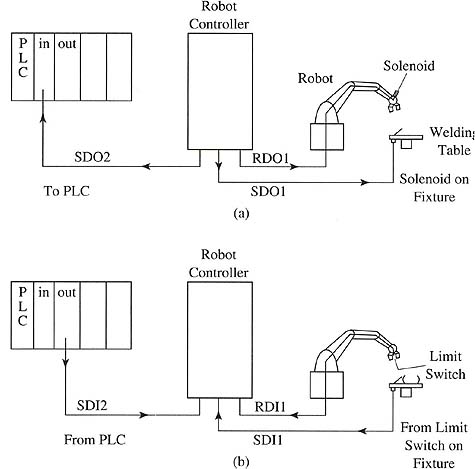
Above: ill.1 (a) Output signals sent from the robot
to a solenoid on its arm, to a solenoid in the work cell, and to the PLC.
(b) Input signals sent from a limit switch on the robot arm, from the
fixture in the work cell, and from the PLC.
From the diagram in ill. 1a notice that output 1 (RDO1) is sent from the robot through its arm to energize and de-energize the solenoid to turn on air for the vacuum gripper. Since this signal is an on/off type signal, it's referred to as a digital signal. Since it comes from the robot's arm, it's identified as a robot digital output (RDO). Output 2 is sent from the first robot's cabinet to the fixture on the indexing table to energize the clamp solenoid for the fixture. This signal is also an on/off signal, so it's a digital signal, but since it comes from the robot cabinet rather than the robot's arm, it will be called a service digital output (SDO).
At first to a new technician it does not become apparent why these two signals are identified differently since they are both outputs. But on closer examination one will see that the problem arises from where the signals are sent. Since the first signal is sent through the robot arm to the solenoid that's mounted on the end of its arm, the cable to deliver this signal must be routed through all of the moving parts of the robot's arm to enable the cable to move with the robot as it moves from point to point. The destination of the second output signal is on the indexing table that's located in the work cell. Since the indexing table does not move with the robot arm, its signal must come from a separate cable that runs from the robot cabinet where the output module is located to the service area of the work cell where the indexing table is located. That is, when one of the output signals is bad, one must first determine if its signal comes from the cable in the robot arm or from the cable that's routed to the work cell service area.
The third output signal is sent from the first robot to the PLC that acts as the cell controller where it provides sequential information to all the robots in the cell. This signal is sent through the output cable that's sent directly to the PLC through a second service cable, so it will also be called an SDO. Note that the signal between the robot and the PLC could be transmitted on a local area network (LAN). The operation of local area networks is explained in are explained here. Notice now that the robot can have multiple service cables to send signals directly to other robots, the PLC, or parts of the work cell service area. Typically each cable is routed to its own set of input and output modules. For instance, the first cable for the robot arm signals may be connected to output module 1. The cable for the work cell service area is connected to output module 2, and the cable to the PLC is connected to output module 3.
In ill. 1b notice the input signals to the first robot. Input 1 is a limit switch located in the vacuum gripper that's actuated when a part is picked up by the robot. This signal is an on/off signal and it's called a digital input signal. Since the limit switch is mounted in the gripper at the end of the arm, the wires that carry this signal must be routed through the robot arm to the robot cabinet. Since the cable is routed through the robot's arm, this signal will be called a robot digital input (RDI).
The second input signal comes from a limit switch mounted to the fixture on the indexing table. This limit switch indicates when the fixture is open or closed. Since it's an on/off signal it's also called a digital signal, but in this case the switch is located in the work cell service area so it's called a service digital input (SDI). The third input signal comes from the PLC to tell the robot that the second robot in the cell has completed its welding program and the part is ready to be picked up and moved to the next station in the cell. Since the parts-handling robot and welding robot both use the same area to perform their jobs, it's vitally important that the PLC is used to direct traffic so that only one robot can enter the work area at a time.
| Top of Page | PREV: Comparison of Robot Actuators | NEXT: Input Circuits for Industrial Robot Signals |