AMAZON multi-meters discounts AMAZON oscilloscope discounts
Both open-loop and closed-loop control systems need alarm points to alert the operators or supervisors of the condition of the system. Process alarms are used in a system to set the maximum and minimum limits that the system is allowed to reach. These limits are determined by the equipment manufacturer so that the equipment will not harm people who must work around the process and so that the equipment will not be damaged while operating. ill. 1 shows examples of process alarms.
For instance, the alarms on a heating system may be set at 600°F and 32°F. These values were determined because temperatures above 600°F will damage the furnace lining, and temperatures below 32°F will allow moisture to freeze and damage seals. If the system controls the level of liquid in a tank, the high and low alarms may be set as a percentage of the level of a full tank. The high-level alarm is set at 90% so the tank will not overfill, and the low-level alarm at 10% so the level doesn't go completely empty when a pump is running and cause the pump to cavitate and fail. Once the process alarms are set for a controller, they shouldn't be changed.
Deviation alarms are used primarily for quality control. These alarms are set to be an amount that's added to and subtracted from the SP. For instance, if the SP for a temperature controller is 400°F, and the quality will be affected if the temperature deviates 10°F above or below the SP, the deviation alarm would be set at +/-10°F. See Figure 2 below.
The important point to remember about the deviation alarm is that if the SP is changed to 450°F, the alarms would remain plus 10°F and minus 10°F and they would move with the SP. The new alarm points would be 440°F and 460°F.
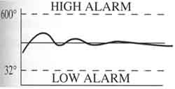
Above: ill. 1: Example of high and low process alarms. Notice that the high alarm is set at 600°F and the low alarm is set at 32°F.
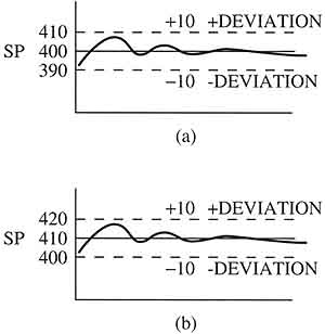
Above: ill. 2 (a) Deviation alarm is set at 10° above and below the setpoint.
(b) This graph shows a change in the setpoint from 400° to 410°. Notice that
the deviation alarms remain at +/-10°, so now they will be set for 420° and 400°.
PREV: Adjusting
GainAdjusting Gain, Reset, and Rate After a System Has Been Running
NEXT: Inner and Outer Alarm Bands