AMAZON multi-meters discounts AMAZON oscilloscope discounts
INTRODUCTION
High-voltage systems* have three uniquely hazardous characteristics. First, the likelihood of an arc occurring increases as the system voltage increases. Although arc energies in high voltage systems are often smaller than low-voltage circuits, the chance of an arc occurring is greater. Second, most workers do not have much experience working on or around such systems. Personnel inexperience can lead to very serious accidents and injuries. And finally, high voltages can puncture through the keratin skin layer, virtually eliminating the only significant skin resistance. Lack of knowledge can be corrected by personnel training.
Section 14 covers the topic of personnel training in great detail.
The energy content and skin-puncturing characteristics of high-voltage systems are inherent to their nature. Safety precautions must be strictly observed to reduce the possibility of accidents, and safety equipment must be worn to reduce the severity of accidents.
AMAZON multi-meters discounts AMAZON oscilloscope discountsThis section highlights some of the key or critical safety concepts related to high-voltage systems. Many of the types of safety precautions used in high-voltage systems are identical to those used in low-voltage systems. Such precautions have been repeated in this section.
HIGH-VOLTAGE EQUIPMENT
Current Transformers
Note: The material in this section applies to current transformers (CTs) used in low-, medium-, and high-voltage circuits. It is included in this section because CTs are much more common in medium- and high-voltage systems.
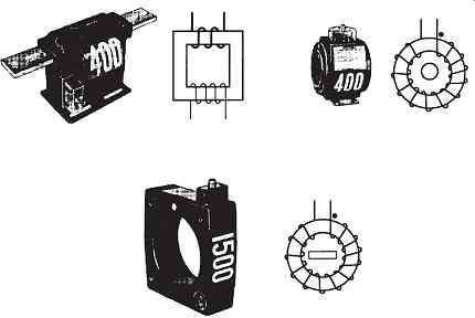
FIG. 1 Typical current transformers. (AVO Training Institute.)
CTs ( FIG. 1) are used to reduce primary current levels to lower values that are usable by instruments such as meters and protective relays. In doing this, the primary winding of the CT is connected in series with the system load current and the secondary winding is connected to the instruments ( FIG. 2).
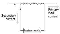
FIG. 2 Schematic diagram of a current transformer connection.
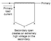
FIG. 3 Open circuit on secondary of current transformer.
If the secondary of an energized transformer is open-circuited, an extremely high voltage will appear at the secondary ( FIG. 3). Depending on the type of transformer and the conditions at the time of the open circuit, this high voltage can create shock, arc, and blast hazards.
CTs can explode violently when their secondary circuits are opened.
Caution: Never open-circuit the secondary of an energized CT. A CT secondary circuit should always be terminated with rated load or a short circuit.
When working on or near CT circuits, personnel should always be aware of the hazard and should wear rubber gloves, arc protective clothing, and face shields if working on the wiring for the circuit. The primary circuit should be de-energized before the secondary wiring is opened.
GROUNDING SYSTEMS OF OVER 1000 V
The subject of electrical grounding is a complex one. The following sections focus on the grounding concepts and requirements of medium- and high-voltage systems as they relate to safety. Section 5 of this handbook provides a much more in-depth coverage of electrical grounding principles and requirements. Also, the reader may refer to the various ANSI/ IEEE standards including IEEE Guide for Safety in AC Substation Grounding.
What Is a Ground?
A ground is an electrically conducting connection between equipment or an electric circuit and the earth, or to some conducting body that serves in place of the earth. If the ground is properly made, the earth or conducting body and the circuit or system will all maintain the same relative voltage.
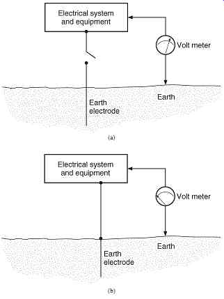
FIG. 4 Grounding. (a) Before system is grounded, a voltage exists between the
system and the earth; (b) when ground connection is made, no volt age exists.
FIG. 4a shows an electrical system that is not grounded. In such a situation, a voltage will exist between the ground and some of the metallic components of the power system. In FIG. 4b, the earth connection has been made. When the system is grounded, the voltage is reduced to zero between the previously energized sections of the system.
Bonding versus Grounding
Bonding is the permanent joining of metallic parts to form a continuous, conductive path. Since the earth is generally not a good conductor, bonding is used to provide a low-impedance metallic path between all metallic parts. This, in essence, bypasses the earth and overcomes its relatively high impedance. A good grounding system is a combination of solid connections between metallic parts and the earth as well as between all metallic parts.
Voltage Hazards
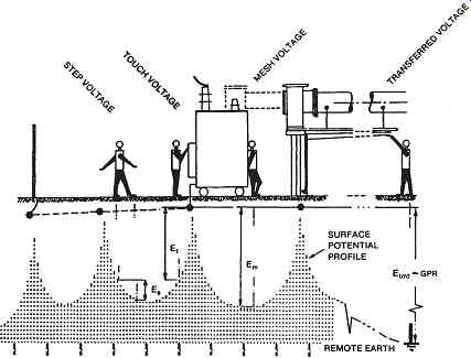
FIG. 5 Four voltage hazards related to system grounding. (Courtesy Institute
of Electrical and Electronics Engineers.)
FIG. 5 illustrates the four standard voltage hazards that are associated with and relieved by proper system grounding. If a system is ungrounded and the non-energized metallic parts become energized, the metallic parts will have a measurable voltage between themselves and ground. If the system is grounded by driving ground electrodes into the earth, current will flow from the rods into the earth. At each ground electrode, the voltage will rise relative to the remote reference point. The voltage will drop off away from the electrodes and peak at each electrode. This situation creates the four types of voltage hazards as follows:
• Step voltage. As a worker steps across the ground, the front foot will be at a different potential than the rear foot. This effect is caused by the voltage gradient created by the ground electrodes ( FIG. 5). Step voltage can easily reach lethal levels. Step voltage can be mitigated by increasing the number of grounding electrodes, increasing bonding between the metal parts, and employing a grounding grid.
• Touch voltage. Because of the voltage gradient, the voltage of the earth, only a short distance from the grounded metallic equipment, will be different from the voltage of the equipment. Thus, if a worker touches the grounded equipment, his or her feet will be at a different potential than his or her hands. This voltage can be lethal. Touch voltage is mitigated by increasing the number of grounding electrodes, increasing bonding between metal parts, and employing a grounding grid.
• Mesh voltage. Mesh voltage is the worst case of touch voltage. Cause, effect, and mitigation methods are identical to those described previously under touch voltage.
• Transferred voltage. Because metal parts have a much lower impedance than the earth, the voltage drop between remote locations is lower on the metallic connections than the earth. This means that the earth may be at a significantly different voltage than the metallic connections. Transferred voltages are particularly noticeable on neutral wires, which are grounded at the service point and nowhere else. Transferred potential can be mitigated by providing the entire area with a ground grid; however, this solution is infeasible in any but the smallest systems. Transferred voltage must be mitigated by avoiding contact with conductors from remote locations and/or using rubber insulating gloves.
System Grounds
What Is a System Ground? A system ground is the connection of one of the conductors to the earth. Such a connection is accomplished by connecting an electric wire to the selected system conductor and the grounding electrode.
Why Are Systems Grounded? Power systems have conductors grounded for a variety of safety and operational reasons, including the following:
• Grounded systems provide sufficient short-circuit current for efficient operation of protective equipment.
• Grounded systems are less prone to transient overvoltages that can cause insulation failures.
• Grounded systems are generally more easily protected from lightning.
• Solidly grounded systems are less prone to resonant conditions that can cause equipment and insulation failures.
What Systems Must Be Grounded? The NEC allows the grounding of permanently installed electrical utilization systems and requires the grounding of mobile electrical supply systems. If the mobile supply system is supplied by a high-voltage delta system, the NEC requires that a ground be derived using a grounding transformer.
The National Electrical Safety Code requires that electric utility supply systems be grounded.
How Are Systems Grounded? Electrical systems are grounded by connecting one of the electrical conductors to earth or some conductive object that replaces the earth. Ship hulls are examples of grounds that do not involve the earth. The conductor chosen and the location of the ground are determined as part of the engineering design for the system. With systems that have delta transformer or generator windings, the neutral, and therefore the ground point, can be derived by using a grounding transformer. FIG. 6 shows a grounded wye-delta transformer used to derive a system neutral and ground. FIG. 7 shows a zigzag transformer used for the same purpose.
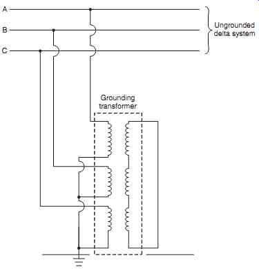
FIG. 6 Grounded wye-delta transformer used to derive a system ground.
The zigzag transformer ( FIG. 7) is the most commonly used method for deriving grounds on high-voltage systems. The windings consist of six equal parts, each designed for one-third of the line-to-line voltage; two of these parts are placed on each leg and connected as shown in FIG. 7. In the case of a ground fault on any line, the ground current flows equally in the three legs of the autotransformer, and the interconnection offers the minimum impedance to the flow of the single-phase fault current.
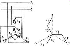
FIG. 7 Grounding autotransformer with interconnected Y (also called
zigzag windings).
Equipment Grounds
What Is an Equipment Ground? An equipment ground is an electrically conductive connection between the metallic parts of equipment and the earth. For example, transformer cases and cores are connected to the earth-this connection is called an equipment ground. Note that the metallic parts of equipment are grounded and bonded together. This bonding serves to reduce the voltage potential between all metallic parts and the earth.
Why Is Equipment Grounded? The equipment ground is one of the most important aspects of grounding as far as safety is concerned. Workers are constantly in contact with transformer shells, raceways, conduits, switchgear frames, and all the other conductive, non-current-carrying parts. Proper equipment grounding and bonding ensures that the volt age to which workers will be subjected is kept to a minimum. Proper bonding and grounding mitigates touch and step voltages.
How Is Equipment Grounded? The NEC requires that the path to ground from circuits, equipment, and metal enclosures must meet the conditions listed in Table 1. Equipment used in grounded systems is grounded by bonding the equipment grounding conductor to the grounded service conductor and the grounding electrode conductor. That is, the equipment ground is connected to the system ground. Equipment used in ungrounded systems is grounded by bonding the equipment grounding conductor to the grounding electrode conductor.
=========
TABLE 1 Equipment Grounding requirements
• Must be permanent and continuous
• Must have the capacity to conduct any fault current likely to be imposed on it
• Must have sufficiently low impedance to limit the voltage to ground and to facilitate the operation of the circuit-protective devices
============
What Equipment Must Be Grounded? All non-current-carrying metal parts of fixed, portable, and mobile high-voltage equipment and associated fences, housings, enclosures, and supporting structures shall be grounded.
The NEC does allow two exceptions to this rule: High-voltage equipment does not have to be grounded if
1. it is isolated from ground and located so as to prevent any person who can make contact with ground from contacting the metal parts when the equipment is energized.
2. it is certain pole-mounted distribution equipment that is exempted.
Refer to the current edition of the NEC for detailed information.
SAFETY EQUIPMENT
Overview
Since the amount of available energy in the system determines its lethal effects, and since high-voltage systems are generally very high-energy systems, high-voltage systems are extremely hazardous and should be treated with the utmost respect.
The following sections describe the types of safety equipment that should be worn by persons working on or near energized, high-voltage conductors. The recommendations given are minimum recommendations. If additional or more stringent protection is desired or required, it should be worn. Refer to the tables in Section 4 for specific recommendations.
Hard Hats
Protective headgear for persons working on or near energized, high-voltage circuits should provide both mechanical and electrical protection. Personnel working on or near energized high-voltage circuits should be supplied with and should wear ANSI class E helmets. ANSI class G and class C helmets are not acceptable. The ANSI class G helmet is not rated or tested for use in high-voltage circuits and the ANSI class G helmet provides no electrical insulation at all. Table 2 summarizes the characteristics of the three ANSI classes. Note that class G and E were formerly class A and B, respectively.
============
TABLE 2 Summary of the Characteristics for ANSI Class C, G, and E Hard Hats
Class Description Comments
[
C
E
G
]
[
Intended to reduce the force of impact of falling objects. This class offers no electrical protection.
Reduce the impact of falling objects and reduce danger of contact with exposed high-voltage conductors. Representative sample shells are proof-tested at 20,000 V phase to ground.
Reduce the impact of falling objects and reduce danger of contact with exposed, low-voltage conductors. Representative sample shells are proof-tested at 2200 V phase to ground.
]
[ Should not be worn by personnel working on or around energized conductors of any voltage recommended to be worn by personnel working around high- and low-voltage circuits recommended to be worn by personnel working around only low-voltage circuits
]
============
Eye Protection
High-voltage systems are capable of producing extremely powerful and hazardous electric arcs and blasts; therefore, eye protection for electrical workers should provide protection against heat and optical radiation. ANSI standard Z87.1 provides a selection chart as well as a chart that illustrates the various protection options available. The selection chart is reproduced in this section as Table 3 and eye protection options are shown in FIG. 8.
Electrical workers should consider using eye protection that combines both heat and optical radiation protection. Table 3 and FIG. 8 show several different types of equipment that will provide such protection including types B, C, D, E, and F. If arcing and molten splashing are possible, as with open-door switching or racking of circuit breakers, the type N eye protection should be employed.
Arc Protection
High-voltage systems create and sustain significant electric arcs accompanied by electric blast.
Workers performing routine work on or around energized, high-voltage conductors should wear flame-retardant work clothing or its equivalent with a rating determined by the incident energy to which they will be exposed. An arc-flash study is the best approach to determine the required rating. Workers operating open-air switches or performing open-door switching procedures should wear flame-retardant flash suits or their equivalent with an arc rating also determined by the incident energy to which they will be exposed. Refer to Section 4 for methods that can be used to calculate required flash clothing weights.
Rubber Insulating Equipment
Rubber insulating equipment and appropriate leather protectors should be used by personnel who are working on or around energized, high-voltage conductors. Rubber gloves, rubber sleeves, rubber blankets, line hose, and other such protective devices should be employed any time workers must approach such conductors. Rubber insulating equipment used around high-voltage systems must have a rating sufficient for the voltage of the system. ANSI class 1, 2, 3, or 4 rubber insulating goods should be employed as required.
TABLE 3 Eye Protection Selection Chart
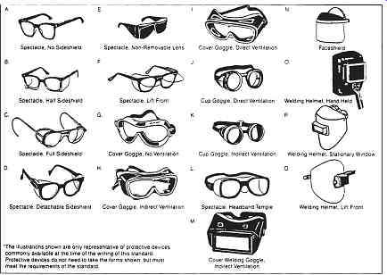
FIG. 8 Eye protection devices. Refer to Table 3 for selection criteria.
Voltage-Testing Devices
Proximity or contact testers intended for use in high-voltage circuits should be used to test circuits and to verify that they are de-energized and safe to work on. Voltage-testing devices are described in Section 3. An example of a high-voltage-measuring instrument is shown in FIG. 9.
ASTM standard F 1796 is the standard defining proximity testers.
SAFETY PROCEDURES
General
The general procedures described in Section 4 should be used on all high-voltage circuits.
The following sections describe key procedures that apply to high-voltage circuits.
Approach Distances
Although approach distances are laid out in a number of OSHA references, the NFPA 70E provides a much more useful and practical concept for approach distances. The following paragraphs identify methods that may be used to determine approach distances.
Refer to Section 4-Fig. 4.35 and Table 4.15-for reference to the terms used in the following section.
Crossing the Limited Approach Boundary. Qualified workers may cross the limited approach boundary if they are qualified to perform the work. Unqualified workers are allowed to cross the limited approach boundary as long as they are continuously escorted by and under the constant direct supervision of a qualified person.
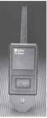
FIG. 9 "TIC" tracer proximity voltage sensor for use on circuits
up to 35,000 V.
Requirements for Crossing the Restricted Approach Boundary. To cross the restricted approach boundary, the following criteria must be met:
• The worker must be qualified to do the work.
• There must be a plan in place that is documented and approved by the employer.
• The worker must be certain that no part of the body crosses the restricted approach boundary.
• The worker must work to minimize the risk that may be caused by inadvertent movement by keeping as much of the body out of the restricted space as possible. Allow only protected body parts to enter the restricted space as necessary to complete the work.
• Personal protective equipment must be used appropriate for the hazards of the exposed energized conductor.
Requirements for Crossing the Prohibited Approach Boundary. NFPA 70E considers crossing the prohibited approach boundary to be the same as working on or contacting an energized conductor. To cross into the prohibited space, the following requirements must be met:
• The worker must have specified training required to work on energized conductors or circuit parts.
• There must be a plan in place that is documented and approved by the employer.
• A complete risk analysis must be performed.
• Authorized management must review and approve the plan and the risk analysis.
• Personal protective equipment must be used appropriate for the hazards of the exposed energized conductor.
Voltage Measurement
The voltage-measurement techniques defined in Section 4 should be employed on circuits of all voltages.
Locking and Tagging
Lockout-tagout and energy control procedures apply to circuits of all voltage levels. Refer to Section 4 for detailed discussions of lockout-tagout procedures.
Closing Protective Devices after Operation
Workers should never reclose any protective device after it has operated, until it has been determined that it is safe to do so. Several criteria may be used to determine whether it is safe to reclose the protective device (Table 4). Other conditions may or may not indicate a safe reclosing situation.
=========
TABLE 4 Typical Situations That May Allow reclosing of a Protective Device
That Has Operated
• The faulted section of the system is found and repaired.
• The nature of the protective device makes it clear that no hazard is present. For example, if the device that operated is an overload type of device, it may be safe to reclose.
• The reclosing operation can be made in such a way that the workers are not exposed to additional hazard. For example, if the reclosing operation can be made by remote control, and if all personnel are kept away from all parts of the circuit, it may be reclosed.
| Top of Page | PREV. | NEXT | Index |