AMAZON multi-meters discounts AMAZON oscilloscope discounts
INTRODUCTION
The way work is performed in or around an electrical power system is just as important as the safety equipment that is used. Proper voltage measurement can mean the difference between life and death. Standing in the right place during switching operations can mitigate or eliminate the effects of an electric arc or blast, and proper application of safety grounds can prevent an accidental reenergization from becoming a fatality.
This section summarizes many industry-accepted practices for working on or around energized electric power circuits. The methods and techniques covered in this section should be used as guidelines. Local work rules and regulatory standards always take precedence. Note that any and all safety procedures should be reviewed at least annually. System changes, employee reassignments, or accidents should be considered excellent reasons for modification of existing procedures or implementation of new procedures.
Safety is the one truly personal concern in an electric power system. In the majority of electrical accidents, the injured victim was the so-called last link in the chain. The use of proper procedures and/or proper safety equipment could have prevented the accident. Equipment and procedures can be provided, but only the individual employee can make the decision to use them. Employees must be impressed with the knowledge that only they can make this final decision-a decision that may result in life or death.
Caution: This section presents several procedures that require technical calculations using a variety of mathematical and engineering applications. These calculations should be performed or evaluated only by qualified, experienced engineers or other technical personnel with the requisite knowledge and skills.
THE SIX-STEP SAFETY METHOD
Table 1 lists six important steps to practicing safe behavior and will serve as the foundation for a personnel safety philosophy. If implemented, this method will greatly enhance the safe and efficient performance of electrical work.
Individuals are responsible for their own safety. The steps listed in Table 1 are all individual steps that can be taken by anyone who works on or around electric power circuits and conductors.
- • Think-be aware.
- • Understand your procedures.
- • Follow your procedures.
- • Use appropriate safety equipment.
- • Ask if you are unsure, and do not assume.
- • Do not answer if you do not know.
TABLE 1 Six-Step Safety Method
Think--Be Aware
Many accidents could have been prevented if the injured victim had concentrated on the safety aspects of the job. Thinking about personal or job-related problems while working on or near energized conductors is a one-way ticket to an accident. Always stay alert to the electrical hazards around the work area.
Understand Your Procedures
Every company has defined safety procedures that are to be followed. Workers should be thoroughly familiar with all the safety procedures that affect their jobs. Knowledge of the required steps and the reasons for those steps can save a life. All employees should go through extensive safety training.
Follow Your Procedures
In the past, some facilities have allowed the violation of safety procedures in the name of production. Such actions are in violation of the law and have invariably proven to be costly in terms of human injury and/or death. Violation of safety procedures without good cause should be a discharge offense. What constitutes "good cause" must be decided on a local basis; how ever, excuses of lesser significance than immediate danger to life should not be acceptable.
Use Appropriate Safety Equipment
No matter how meticulous workers are, accidents do occasionally happen. Equipment failures, lightning strikes, switching surges, and other such events can cause shock, arc, or blast.
Also, sometimes it becomes necessary for employees to work on or very close to energized conductors, which increases the chance of accidental contact.
Because of these reasons, appropriate safety equipment should be used any time workers are exposed to the possibility of electrical hazards. Remember that nothing is sadder than an accident report that explains that the dead or injured worker was not wearing safety equipment.
Ask If You Are Unsure, and Do Not Assume
Ignorance kills and injures many people each year. No one should ever get fired for asking a question-especially if it is a safety-related question. Anyone who is uncertain about a particular situation should be encouraged to ask questions, which should then be answered by a qualified person immediately and to the fullest extent possible.
Do Not Answer If You Do Not Know
No one should answer a question if they are not certain of the answer. Self-proclaimed experts should keep their opinions to themselves.
JOB BRIEFINGS
Definition
A job briefing (sometimes called a "tailgate meeting") is a meeting that informs all workers of the job requirements. In particular, a job briefing is used to alert workers to potential safety hazards. A job briefing need not be a formal gathering; however, it is mandatory that all workers involved attend, and worker attendance should be documented.
What Should Be Included?
OSHA rules require that a job briefing discuss, at a minimum, the following issues:
• Special precautions to be taken
• Hazards associated with the job
• Energy control procedures
• Procedures and policies
• Personal protective equipment (PPE)
Note that the first letters of each of these bulleted items form the acronym SHEPP, which can be used to help remember the important issues that need to be discussed.
Job briefings should be proactive meetings in which workers are informally quizzed to make certain that they fully understand the safety issues they will face.
When Should Job Briefings Be Held?
• At the beginning of each shift
• At the beginning of any new job
• Any time that job conditions change
• When new personnel are introduced to an ongoing job
ENERGIZED OR DE-ENERGIZED?
The Fundamental Rules
All regulatory standards are quite clear in their requirements to de- energize a circuit before employees work on or near it. Stated simply:
All circuits and components to which employees may be exposed should be de energized before work begins.
Some references, such as NFPA 70e, refer to this process as making a work area electrically safe. this phrase is preferred over de-energized since it specifically encompasses turning equipment off, locking and tagging, voltage measurement, and so on.
A few basic points will clarify this requirement:
• Production or loss of production is never an acceptable, sole reason to work on or near an energized circuit.
• If work can be rescheduled to be done de-energized, it should be rescheduled.
• De- energized troubleshooting is always preferred over energized troubleshooting.
• The qualified employee doing the work must always make the final decision as to whether the circuit is to be de- energized. Such a decision must be free of any repercussions from supervision and management.
A Hot- Work Decision Tree
FIG. 1 illustrates a method that may be used to determine the need to work on a circuit when it is energized. The numbers in the following explanation refer to the numbers assigned to each of the decision blocks shown in FIG. 1.
1. Work performed on or near circuits of less than 50 V to ground may usually be considered to be de-energized work. Note that if the circuit has high arcing capability, decision 1 should be answered as "Yes."
2. If de-energizing simply changes the hazard from one type to another, or if it actually increases the degree of hazard, this decision should be answered "Yes." Table 2 lists the types of additional hazards that should be considered in answering this decision.
3. The need to keep production up is common to all industries-manufacturing, petro chemical, mining, steel, aluminum, electric utilities, shipyards, and ships. However, many employers abuse the concept that "production must continue." the following points should clarify when production issues may be allowed to influence the decision to de-energize.
a. Shutdown of a continuous process that will add extraordinary collateral costs may be a signal to work on the circuit energized. Table 3 lists examples of these types of collateral costs.
b. Shutdown of a simple system that does not introduce the types of problems identified in Table 3 should always be undertaken rather than allowing energized work.
4. In some cases, the very nature of the work or the equipment requires that the circuit remain energized. Table 4 shows three of the most common examples of such work.
Note, however, that this work should still be de-energized if it is possible to do it that way. For example, troubleshooting a motor starter may be faster with the circuit energized; however, if it can be done de-energized it should be, even at the cost of a little more time.
5. If decision 2 or 3 leads in the direction of energized work, the next decision should be rescheduling. If energized work can be done de- energized on a different shift or at a later time, it should be postponed. Many companies miss this elegantly simple alternative to exposing their personnel to hazardous electrical energy.
6. The final, and arguably the most important, decision of all is to determine whether the work can be done safely. If, in the opinion of the qualified personnel assessing the job, the work is simply too dangerous to do with the circuits energized, then it must be de- energized.
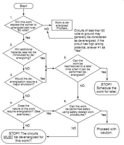
FIG. 1 hot-work flowchart.
- • Interruption of life-support systems
- • Deactivation of emergency alarms
- • Shutdown of ventilation to hazardous locations
- • Removal of illumination from the work area
TABLE 2 Examples of additional hazards
- • Excessive restart times in continuous process systems
- • High product loss costs (in polyethylene process, for example, the product has to be physically dug out of process equipment after an unscheduled outage)
- TABLE 3 Examples of Collateral Costs That May Justify Energized Work
- • Testing electrical circuits (to verify de- energization, for example)
- • Troubleshooting complex controls
- • Infrared scan
TABLE 4 Examples of Work That May Require Energization of Circuits
- 1. All energy control devices feeding the work area must be opened.
- 2. Locks and tags shall be placed on the energy control devices.
- 3. Voltage measurements shall be made at the point(s) of exposure to verify that the circuit is de- energized.
- 4. Safety grounds (if required) shall be placed to ensure the existence of an equipotential work zone.
- 5. The work area must be closely inspected by a qualified person to make certain that no energized parts remain. This critical step is often missed.
TABLE 5 Steps required before De-energized Work may commence
After the Decision Is Made
If the work must be done energized, all employees who work on or near energized conductors must be qualified to do the work, must use appropriate personal protective equipment, and must use appropriate safety- related work practices.
If the circuits are to be de-energized, the steps listed in Table 5 must be followed. Note that proper, safe procedures for each of the items in Table 5 are discussed later in this section.
SAFE SWITCHING OF POWER SYSTEMS
Introduction
The most basic safety procedure is to de-energize the parts of the system to which workers may be exposed. This procedure virtually eliminates the hazards of shock, arc, and blast. De-energizing, also called clearing, involves more than simply turning the switches off. To ensure maximum safety, de-energizing procedures that are precise for each situation should be written.
The following sections discuss the proper safety techniques for operation of various types of equipment and provide de-energizing and reenergizing procedures that may be used as the basis for the development of site-specific procedures. Please note that specific procedures may vary depending on the application and type of equipment. Refer to manufacturer's and/or local facility procedures for specific information. The methods given in these sections should be considered minimum requirements. These procedures assume that the device is being operated when one or both sides are energized.
Caution:
• Switching of electric power should be done only by qualified personnel who are familiar with the equipment and trained to recognize and avoid the safety hazards associated with that equipment.
• Non-load-interrupting devices that are not intended to interrupt any current flow should never be used to interrupt current flow. They should be operated only after all loads have been disconnected from the circuit by other means.
• Circuit breaks should never be closed after they interrupt a fault until the cause of the fault has been determined and corrected. Most circuit breakers are tested to operate only once at their maximum interrupting rating.
Remote Operation
There are at least three different ways that electrical switchgear such as circuit breakers and switches can be operated safely.
1. Operating from a remote control room
2. Operating using a remote operating device
3. Operating manually from the device panel
Operating from a Remote Control Room. Many companies are opting to install remote switching centers to better protect their workers. These types of installations are being used extensively in new construction and are being retrofitted into many existing facilities. This type of system requires that the devices to be operated can be operated electrically. Circuit breakers, for example, are equipped with electrical close, open, and/or racking accessories. When the operator in the remote control room operates the remote control handle, an electrical signal is sent to the breaker, causing it to open, close, or rack in or out.
These types of installations provide a very high level of safety because the worker is completely isolated from the gear. If the gear arcs or explodes, the worker is protected by brick or concrete walls.
All such control rooms have the ability to remotely open or close the breaker. However, since the most dangerous part of the operation is racking the breaker (moving it to connect or disconnect from the electrical bus), optimal safety is not realized unless the breaker can be racked remotely as well.
Operating Using a Remote Operating Device. Several companies are manufacturing and selling remote operating appliances. These devices have an operating mechanism that is temporarily (or permanently if desired) connected to the gear. The mechanism is designed so that, when triggered by the operator, it will physically manipulate the toggle switch, push button, or pistol-grip switch and close, open, charge, rack, or otherwise operate the circuit breaker or switch.
The control box is held by the operator and connected to the operating mechanism by an umbilical cable. The cable is long enough to allow the operator to stand well outside the flash hazard boundary. Of course, standing as far away as possible is the safest approach.
FIG. 2 shows the control box of one such device in place to open or close a medium voltage circuit breaker. FIG. 3 is an operator's-eye view of the operating mechanism, umbilical cable, and control box for the same device. Note that the control box has a switch for open and close as well as a toggle switch to control the amount of movement made by the operating mechanism.
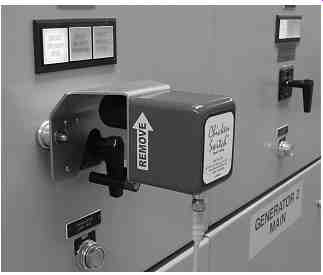
FIG. 2 operating mechanism of a remote open-close appliance. (Courtesy
www.chickenswitch.com)
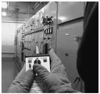
FIG. 3 View of operating control and umbilical cable for device shown
in fig. 2. (Courtesy www.chickenswitch.com)
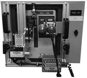
FIG. 4 operating mechanism designed for use on a CH magnum DS. (Courtesy
CBSArcSafe, CBSArcSafe.com)
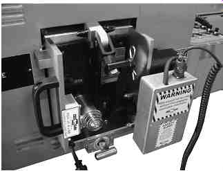
FIG. 5 operating mechanism designed for use on K-line circuit breakers
(old ITE now ABB). (Courtesy CBSArcSafe, CBSArcSafe.com)
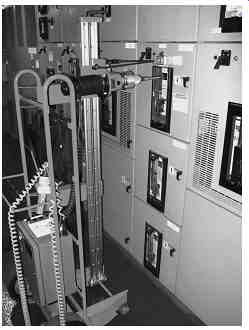
FIG. 6 a device designed to remove and install circuit breakers remotely.
(Courtesy CBSArcSafe, CBSArcSafe.com)
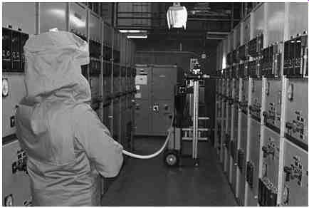
FIG. 7 View of operator and umbilical cable for device shown in FIG.
6. (Courtesy CBSArcSafe, CBSArcSafe.com)
FIG. 4 shows another manufacturer's operating mechanism attached to a Ch magnum Ds low-voltage circuit breaker. FIG. 5 shows a different operating mechanism by the same manufacturer. This one is designed for use on ABB (previously ITE) K-line low-voltage circuit breakers. Low-voltage circuit breakers sometimes require manual charging of closing springs. The units shown in figs. 4 and 5 will not only open and close the breakers but also charge the closing springs.
Most electrical accidents involving circuit breakers occur when the breaker is being inserted into or removed from its operating cradle. The action, called racking, has a very critical moment when the circuit breaker connections engage the bus (racking in) or when they disengage the bus (racking out). Because of the way the racking mechanism is designed, workers usually cannot stand to the side of the breaker cubicle where they are safest. This means that should there be a failure that causes an electrical arc and blast, the worker would be directly in the path of the heat and/or pressure.
FIG. 6 shows one manufacturer's solution to this problem. The equipment shown in the figure is designed to rack breakers in or out remotely. The mechanism can be attached to many different breaker types, both low- and medium-voltage, using couplings supplied by the manufacturer. The breaker in this photo is a Siemens RL breaker.
FIG. 7 is a view of the system showing the operator and the umbilical cable. After the unit is connected properly to the breaker, the operator moves away until he or she is at least outside of the flash hazard boundary. With the control panel, the operator starts the racking operation. When the breaker has racked in or out completely, the equipment shuts off automatically.
Although these remote devices will usually allow the worker enough distance to be outside of the flash hazard boundary, it is generally recommended that rated protective clothing be worn anyway. This protects the operator in the event of a catastrophic failure.
Operating Manually from the Device Panel. Although remote operation is being used more and more often, local operation is still the most widely used. Thankfully, this is starting to change, but it will be many years or even decades before remote operation becomes the norm. In addition, some equipment is difficult to set up for remote operation.
The following paragraphs describe various types of electrical gear and how to operate them locally and safely.
Operating Medium-Voltage Switchgear
General Description. Figures 8 through 14 illustrate various types of medium-voltage switchgear and the breakers used in them. In this style of gear, the circuit breaker rolls into the switchgear on wheels as shown in FIG. 9 or on a sliding type of racking mechanism as shown in FIG. 12. The opening and closing of the breaker is performed electrically using a front-panel-mounted, pistol-grip type of control. Turning the grip in one direction (usually counterclockwise) opens the breaker, and turning it in the other direction closes it.
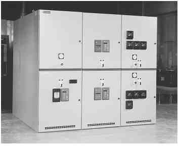
FIG. 8 Medium-voltage metal-clad switchgear. (Courtesy Westinghouse
Electric.)
The breaker connects to the bus and the line via a set of disconnects, visible at the top of FIG. 9 and on the right side of FIG. 12. When the breaker is open, it can be moved toward the front of the cubicle so it disconnects from the bus and line. This action is referred to as racking the breaker. The breaker may be completely removed from the switchgear, or it may be put into two or more auxiliary positions. Racking a circuit breaker is accomplished using removable cranks. These cranks may be of a rotary type or a lever bar that is used to "walk" the breaker from the cubicle.
Most switchgear have two auxiliary positions: the test position and the disconnected position. In the test position, the breaker is disconnected from the bus; however, its control power is still applied through a set of secondary disconnects. This allows technicians to operate the breaker for maintenance purposes. In the disconnected position, the breaker is completely disconnected; however, it is still in the switchgear.
For some types of switchgear, the front panel provides worker protection from shock, arc, and blast. This means that the switchgear is designed to contain arc and blast as long as the door is properly closed and latched. Such gear is called arc-resistant switch gear.
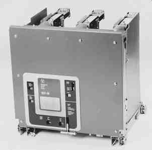
FIG. 9 Circuit breaker used in switchgear shown in FIG. 8. (Courtesy
Westinghouse Electric.)
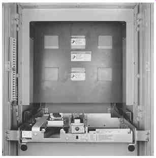
FIG. 10 Switchgear of FIG. 8 with door open showing circuit breaker
cubicle. (Courtesy Westinghouse Electric.)
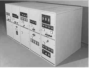
FIG. 11 Metal-clad, medium-voltage switchgear for vacuum-type circuit
breakers. (Courtesy General Electric.)
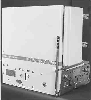
FIG. 12 Medium-voltage, vacuum interrupter circuit breaker used in
switchgear of FIG. 11. (Courtesy General Electric.)
---
Switchgear cubicles Breaker or starter being operated Alternative positions of operating handle Primary operator position (facing away from gear) Backup operator position (facing primary operator) Front of gear Rear of gear
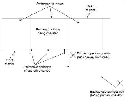
FIG. 13 proper position for operating electrical equipment (top view).
---
Closed-Door Operation. Table 6 lists the recommended safety equipment to be used by operators when performing both closed-door and open-door switching on medium-voltage switchgear. FIG. 13 is a top view of such equipment showing alternative positions for the control handle and the preferred positions for the primary and backup operators. Note that both the primary operator and backup operator should be wearing the recommended clothing. The primary operator is the worker who actually manipulates the handle that opens and/or closes the circuit breaker. The backup operator's responsibility is to support the primary operator in the event there is a problem. The backup operator should be positioned several feet outside of the arc-flash boundary so he or she does not become an additional casualty in the event of a catastrophic failure of the gear. The backup operator may be optional in some facilities.
To operate the switchgear with a closed door, the following steps apply:
1. The primary operator stands to the side of the cubicle containing the breaker to be operated. The side to which he or she stands should be determined by which side the operating handle is on. If the handle is in the middle, the operator should stand on the hinge or the handle side of the door depending on which side is stronger. (refer to the manufacturer.)
2. The primary operator faces away from the gear. Some workers prefer to face the gear to ensure better control. In either case, the primary operator should turn his or her face away from the breaker being operated.
3. The backup operator stands even farther from the cubicle and outside the arc-flash boundary, facing the primary operator.
4. The primary operator reaches across to the operating handle and turns it to open or close the breaker. Note that the primary operator continues to keep his or her face turned away from the gear. Some operators prefer to use a hot stick or a rope for this operation. This keeps the arms as far as possible from any hazard.
5. If the breaker can be racked with the door closed, and if the breaker is to be racked away, the primary operator inserts the racking handle. In this operation, the primary operator may have to face the breaker cubicle.
6. If lockout-tagout procedures are required, the primary operator places the necessary tags and/or locks.
Open-Door Operation. Refer to Table 6 for a minimum listing of safety equipment for this operation. If the door must be open for racking the breaker away from or onto the bus, the following steps should be observed:
1. The breaker is opened as described earlier under closed-door operation.
2. The primary operator opens the cubicle door and racks the breaker to the desired position.
3. If lockout-tagout procedures are required, the primary operator places the necessary tags and/or locks.
Operating Low-Voltage Switchgear
General Description. With some exceptions, the operation of low-voltage switch gear is very similar to the operation of medium-voltage gear. Figures 14 through 17 illustrate various types of low-voltage switchgear and the breakers used in them.
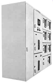
FIG. 14 Low-voltage metal-clad switchgear. (Courtesy General Electric.)
===
TABLE 6 Recommended Minimum Safety Equipment for operating Metal-Clad Switchgear
Closed door (arc-resistant gear only)
• Hard hat-ANSI Z89.1 class e or G (as required by voltage level)
• ANSI Z87.1 safety glasses with side shields
• Flame-resistant work clothing (select using arc-flash calculations) open-door or non-arc-resistant gear
• Hard hat-ANSI Z89.1 class e or G (as required by voltage level)
• ANSI Z87.1 safety glasses with side shields
• Rubber gloves with leather protectors (class according to voltage level)
• Flame-resistant work clothing (select using arc-flash calculations)
===
Note: Closed door means that the front safety panels are closed and latched. If the front panels are not designed to contain blast and arc (such as with arc-resistant switchgear), then open-door protective equipment must be worn.
In this style of gear, the circuit breaker rolls into the switchgear on a sliding type of racking mechanism as in FIG. 17. The circuit breaker is tripped by the release of a powerful set of springs. Depending on the breaker, the springs are released either manually and/ or electrically using a front panel button and/or control switch. The springs may be charged manually and/or electrically, again depending on the breaker.
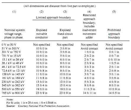
FIG. 15 Low-voltage circuit breaker used in the switchgear shown in
FIG. 14. (Courtesy General Electric.)
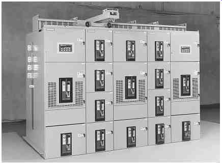
FIG. 16 Low-voltage metal-enclosed switchgear. (Type R switchgear manufactured
by Electrical Apparatus Division of Siemens Energy and Automation, Inc.)
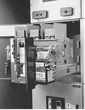
FIG. 17 Low-voltage power circuit breaker racked completely away from
the bus. (Type RL circuit breaker manufactured by Electrical Apparatus
Division of Siemens Energy and Automation, Inc.)
The breakers may be closed either with another set of springs or by means of a manual closing handle. The springs for spring-operated breakers may be charged either manually or electrically. For example, the breaker shown in FIG. 15c is a manually operated breaker. The large gray handle is cranked several times to charge the closing spring. When the spring is fully charged, the breaker may be closed by depressing a small, mechanical button on the face of the breaker. Tripping the breaker is accomplished by depressing another push button. Other breakers have different means of opening and closing.
Low-voltage breakers connect to the bus and the line via a set of disconnects, visible on the right side of FIG. 15b. When the breaker is open, it can be moved toward the front of the cubicle so that it disconnects from the bus and line. This action is referred to as racking the breaker. Racking the larger-size low-voltage breakers is accomplished using removable cranks. These cranks are usually of a rotary type. The breaker may be completely removed from the switchgear, or it may be put into two or more auxiliary positions. Smaller low voltage breakers are racked by simply pulling or pushing them.
Like medium-voltage switchgear, most low-voltage breakers have two auxiliary positions (test and disconnected). In the test position, the breaker is disconnected from the bus; however, its control power and/or auxiliary switches are still applied through a set of secondary disconnects. This allows technicians to operate the breaker for maintenance purposes. In the disconnected position, the breaker is completely disconnected; however, it is still in the switchgear.
For some types of switchgear, the front panel provides worker protection from shock, arc, and blast. This means that the switchgear is designed to contain arc and blast as long as the door is properly closed and latched. Such gear is called arc resistant.
Closed-Door Operation. The closed-door operation of low-voltage breakers is virtually identical to the closed-door operation of medium-voltage circuit breakers. Table 6 lists the recommended safety equipment to be used by operators when performing both closed-door and open-door switching on low-voltage switchgear. Note that both the primary operator and backup operator should be wearing the recommended clothing.
The primary operator is the worker who actually manipulates the handle that opens and/or closes the circuit breaker. The backup operator's responsibility is to back up the primary opera tor in the event there is a problem. The backup operator may be optional in some facilities.
To operate the switchgear with a closed door, the following steps apply:
1. If the breaker requires manual spring charging, the primary operator may face the breaker to obtain the necessary leverage on the cranking handle.
2. After the springs are charged, the primary operator stands to the side of the cubicle containing the breaker to be operated. The side to which he or she stands should be determined by which side the operating handle is on. If the handle is in the middle, the operator should stand on the hinge or the handle side of the door, depending on which side is stronger. (refer to the manufacturer.)
3. The primary operator faces away from the gear (preferred).
4. The backup operator stands even farther from the cubicle and outside the arc-flash boundary, facing the primary operator.
5. The primary operator reaches across to the operating buttons or handle and operates them to open or close the breaker. Note that the primary operator continues to keep his or her face turned away from the gear. Some operators prefer to use a hot stick or a rope for this operation. This keeps the arms as far as possible from any hazard.
6. If the breaker can be racked with the door closed, and if the breaker is to be racked in or out, the primary operator inserts the racking handle and turns it. Note that breakers that are racked manually cannot be racked with the door closed. In this operation, the primary operator may have to face the breaker cubicle.
7. If lockout-tagout procedures are required, the primary operator places the necessary tags and/or locks.
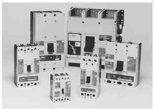
FIG. 18 Various molded-case circuit breakers. (Courtesy Westinghouse
Electric.)
FIG. 19 Panelboards equipped with molded-case circuit breakers.
Open-Door Operation. Refer to Table 6 for a minimum listing of safety equipment for this operation. If the door must be open for racking the breaker, the following steps should be observed:
1. The breaker is opened as described earlier under closed-door operation.
2. The primary operator opens the cubicle door and racks the breaker to the desired position.
3. If lockout-tagout procedures are required, the primary operator places the necessary tags and/or locks.
Also see: Electrical safety systems
| Top of Page | PREV: Electrical Safety Equipment | NEXT: part 2 | Index |