AMAZON multi-meters discounts AMAZON oscilloscope discounts
INTRODUCTION:
The safety aspects of any job or procedure are greatly enhanced by the use of proper tools meters, apparel, and other such equipment. This section outlines the construction and use of a variety of electrical safety equipment. Some of the equipment is used to actually per form work-items such as insulated tools or voltage-measuring devices fall into this category. Other safety products are used strictly to protect the worker, for example, flash suits and rubber goods.
AMAZON multi-meters discounts AMAZON oscilloscope discountsEach specific piece of safety equipment is used to protect the worker from one or more of the numerous electrical safety hazards, and each piece of equipment should be employed when performing various types of jobs in the electric power system.
Always be certain that the clothing or apparel and the meters or tools you are using are designed and tested to match or exceed the incident energy level and the voltage level for the application to which you will be exposed.
GENERAL INSPECTION AND TESTING REQUIREMENTS FOR ELECTRICAL SAFETY EQUIPMENT
Each of the types of electrical safety equipment described in this section has specific inspection and testing requirements. These requirements are identified in each of the individual sections. In addition to specific requirements, the following precaution should always be observed:
Always perform a detailed inspection of any piece of electrical safety equipment before it’s used. Such an inspection should occur at a minimum immediately prior to the beginning of each work shift, and should be repeated any time the equipment has had a chance to be damaged.
Where possible, the guidelines for wearing and/or using the various types of safety equipment discussed in this section are based on existing industry standards. In any event, the guidelines used in this guide should be considered minimum. Requirements for specific locations should be determined on a case- by- case basis using current industry standards.
FLASH AND THERMAL PROTECTION
The extremely high temperatures and heat content of an electric arc can cause extremely painful and/or lethal burns. Since an electric arc can occur at any time in electrical equipment that has not been placed in an electrically safe work condition, the worker must take precautions and wear protection when exposed to potential arc hazards. Note that these sections address equipment for electrical hazard. Fire protection equipment has slightly different requirements and is not covered.
Tbl. 1 itemizes the type of equipment required to protect the worker from the thermal hazards of electric arc. The next sections describe the type of equipment used and will identify when and how to use that equipment.
===
TBL. 1 Equipment Used to protect Workers from Arc hazard
Area of body to be protected | Equipment used
Torso, arms, legs Thermal work uniforms, flash suits
Eyes Face shields, goggles, safety glasses
head Insulating hard hats, flash hoods
hands Rubber gloves with leather
protectors, thermally resistant gloves
===
A Note on When to Use Thermal Protective Clothing
The usage directions given in this section should be used as minimum guidelines only.
Modern technology has enabled the calculation of actual incident arc energies. When these arc energies are compared to the Arc Thermal performance Value (ATpV) discussed later in this section, the exact weight and type of thermal clothing can be determined.
If workers are required to place any part of their body within the flash boundary distance of an energized electrical component, they must wear thermal protective clothing with an ATpV or EBT equal to or greater than the amount of arc energy to which they might be exposed. Section 4 of this handbook provides specific methods for these calculations. The ATpV or EBT for any given material is calculated using the procedures defined in ASTM standard F 1959/F 1959M.
======
TBL. 2 Test Data Drawn from Method 5903.1 of Federal Test Standard 191A Test result measured Description
After-flame Number of seconds (in tenths) during which there is a visible flame remaining on the fabric
Afterglow Number of seconds (in tenths) during which there is a visible glow remaining on the fabric
Char length: length of the fabric in tenths of an inch destroyed by the flame that will readily tear by application of a standard weight
======
Thermal Performance Evaluation
Flame Resistance (FR). Virtually all clothing will ignite when exposed to a sufficient heat source. When the heat source is removed, normal clothing will continue to burn.
Flame- resistant clothing may burn and char when it’s exposed to a heat source, but it won’t continue to burn after the heat source is removed.
The most common test for flame resistance is defined in Method 5903.1 of Federal Test Standard 191A (Flame Resistance of Cloth: Vertical). This test suspends a 12-inch-long specimen of fabric vertically in a holder. The fabric is enclosed and subjected to a con trolled flame on the bottom edge of the fabric for 12 seconds. Tbl. 2 lists the three sets of data that are recorded in this test.
Note that the results are gathered after the flame source has been removed. Note also that the afterglow is not included in most of the industry standards that reference this method.
Arc Thermal Performance Value (ATPV). Research by Stoll and Chianta developed a curve (the so- called Stoll curve) for human tolerance to heat. The curve is based on the minimum incident heat energy (in kJ/m^2 or cal/cm^2) that will cause a second- degree burn on human skin. Modern standards that define the level of thermal protection required are based on the Stoll curve. That is, clothing must be worn that will limit the degree of injury to a second- degree burn. This rating is called the Arc Rating or the Arc Thermal Performance Value (ATpV).
=====
TBL. 3 ASTM Standards Defining Electrical Worker Thermal Clothing
Standard number | Title
F 1506 Standard performance Specification for Textile Materials for Wearing Apparel for Use by Electrical Workers Exposed to Momentary Electric Arc and Related Thermal hazards F 1959 Standard Test Method for Determining the Arc Thermal performance Value of Materials for Clothing F 2178 Standard Test Method for Determining the Arc Rating of Face protective products
=====
Energy Break-Through (EBT). Some types of flame-resistant materials become brittle when exposed to very high temperatures. The combination of the brittleness and the concussion from the electrical blast can cause the material to fail and break open. ASTM has defined this value as the average of the five highest incident energy exposure values below the Stoll curve where the specimens don’t exhibit break open.
Since the EBT is defined for values below the Stoll curve, garments made from such materials can be safely used when exposures will be less than the energy break-through level.
ASTM and Other Standards. The American Society for Testing and Materials (ASTM) has three standards that apply to the thermal protective clothing to be worn by electrical workers. Tbl. 3 identifies these standards.
ASTM standard F 1506 specifies three requirements for workers' clothing in part 6:
1. Thread, bindings, and closures used in garment construction shall not contribute to the severity of injuries to the wearer in the event of a momentary electric arc and related thermal exposure.
2. Afterflame is limited to 2.0 s or less and char length is limited to 6.0 in or less. Afterglow is mentioned but is not judged a serious hazard.
3. Garments must be labeled with the following information:
a. Tracking identification code system
b. Meets requirements of ASTM F 1506
c. Manufacturer's name
d. Size and other associated standard labeling
e. Care instructions and fiber content
Standard F 1959 defines the technical specifications of measuring the Arc Thermal performance Value. Note that garments only pass the 5903.1 method with 6.0 in or less char length and 2.0 s or less afterflame. It’s important to note that ASTM 1959 is a test procedure for testing garment material, not the garment itself.
Standard F 2178 defines the technical specifications for measuring the arc rating for protective face shields used in arc protective clothing. The standard provides methods for arc thermal ratings only and specifically does not address molten materials, fragmentation materials, and other such flying debris.
Usage Standards. The principal standards for electrical worker thermal protection are OShA 1910.269 and ANSI/NFpA 70E. Of these two, 70E is the most rigorous and provides the best level of protection, and it defines user thermal protection requirements on the basis of the ATpV. The usage requirements described in this handbook are based primarily on ANSI/NFpA 70E.
Clothing Materials
Materials used to make industrial clothing fall into two major categories, with several sub categories under each as follows:
1. Non- flame- resistant materials. When these materials are treated with a flame- retardant chemical, they become flame resistant.
a. Natural fibers such as cotton and wool
b. Synthetic fibers such as polyester, nylon, and rayon
2. Flame- resistant materials
a. Non- flame- resistant materials that have been chemically treated to be made flame resistant
b. Inherently flame- resistant materials such as pBI, Kermel, and Nomex The following sections describe some of the more common fibers and identify their general capabilities with respect to thermal performance.
Non-Flame-Resistant Materials
Contrary to some misunderstandings, natural fibers such as cotton and wool are not flame resistant. In fact, the only advantages that natural fibers exhibit over synthetics such as polyester is that they don’t melt into the burn, and the gases that they generate while burning are generally much less toxic than those of the synthetics. Don’t use natural fibers and expect to get the type of protection afforded by true flame- resistant materials.
Cotton. Cotton work clothing made of materials such as denim and flannel is a better choice than clothing made from synthetic materials. Cotton does not melt into the skin when heated; rather, it burns and disintegrates, falling away from the skin. Thick, heavy cotton material provides a minimal barrier from arc temperatures and ignites quickly. At best, cotton provides only minimal thermal protection.
Wool. Wool clothing has essentially the same thermal properties as cotton clothing.
Synthetic Materials. Untreated synthetic clothing materials such as polyester and nylon provide extremely poor thermal protection and should never be used when working in areas where an electric arc may occur. Some synthetic materials actually increase the danger of exposure to an electric arc. Synthetic materials have a tendency to melt into the skin when exposed to high temperatures. This melting causes three major difficulties.
1. The melted material forms a thermal seal that holds in heat and increases the severity of the burn.
2. Circulation is severely limited or cut off completely under the melted material. This slows healing and retards the flow of normal nutrients and infection-fighting white blood cells and antibodies.
3. The removal of the melted material is extremely painful and may increase the systemic trauma already experienced by the burn victim.
Synthetic-Cotton Blends. Synthetic-cotton blends such as polyester-cotton are used to make clothing that is easier to care for. Although slightly less vulnerable to melting than pure polyester, the blends are still extremely vulnerable to the heat of an electric arc and the subsequent plasma cloud. Such blends provide poor thermal protection and should not be used in areas where the hazard of electric arc exists.
Flame-Resistant Materials
Chemically Treated Materials. Both natural and synthetic fibers can be chemically treated to render them flame resistant. Such materials are sometimes used in disposable, coverall- type clothing. While some chemical treatments (such as Borax and boric acid-salt combinations) may be temporary in nature, others are quite satisfactory and may last for the life of the garment.
Historically, chemically treated natural fibers did not exhibit as high an ATpV as synthetic materials when compared by weight. Over the past 10 years, the methods of treating natural fibers have erased any advantage previously exhibited by the synthetic FR materials, and some workers report that the natural fibers are more comfortable to wear in the climatic extremes of heat and cold.
Heavy weights of chemically treated natural fibers may provide superior protection against certain molten metals.
Nomex IIIA. Nomex is an aramid fiber made by the DuPont Company. It has a structure that thickens and carbonizes when exposed to heat. This unique characteristic allows Nomex to provide excellent thermal protection.
Nomex has been modified in the years since it was first introduced. Nomex IIIA is made with an antistatic fiber and is, therefore, suitable for use in hazardous environments such as those with high concentrations of hydrocarbon gas.
Since the characteristics of Nomex are inherent to the fiber, and not a chemical treatment, the thermal protection capabilities of Nomex are not changed by repeated laundering.
Polybenzimidazole (PBI)
PBI is a product of performance products Inc., a subsidiary of hoechst Celanese Corporation. It’s similar to Nomex in that it’s a synthetic fiber made especially to resist high temperatures. pBI is nonflammable, chemically resistant, and heat stable. This heat stability makes it less prone to shrinking or embrittlement when exposed to flame or high temperatures.
PBI does not ignite, melt, or drip in Federal Vertical Flame Tests FSTM 5903 and FSTM 5905. pBI's characteristics are permanent for the life of the garment. hoechst Celanese performed tests that indicate that pBI has heat protection characteristics that are equal to or superior to other materials.
Kermel.* Kermel is a synthetic polyamide imide aramid fiber manufactured in France by Rhone- poulenc. Kermel fiber is only offered in fabrics blended with other fibers. Kermel is blended with wool for dress uniforms, sweaters, and underwear, and with high- tenacity aramid for bunker gear and gloves. In the professional firefighter and work wear areas, Kermel is offered in a 50/50 blend with FR viscose rayon.
Like other synthetic flame- retardant materials, Kermel is flame resistant and does not drip or melt when heated.
Material Comparisons. Tbl. 4 illustrates the relative properties of the various types of clothing materials. The information given in Tbl. 4 is drawn from general industry experience and/or manufacturer experiments.
Work Clothing
Construction. Work clothing used for routine day-to-day electrical safety may be employed as secondary flash protection. Flame-retardant cotton, flame-retardant synthetic cotton blend, Nomex, pBI, or other flame-retardant materials are preferred. The clothing should meet the following minimum requirements:
1. Long sleeves to provide full arm protection
2. Sufficient weight for both thermal and mechanical protection
3. Sufficient arc rating (ATpV) for the locations where used
The suggested minimum is 4 ounces per square yard (oz/yd^2) if synthetics such as Nomex or pBI are used and 7 to 8 oz/yd^2 if flame-retardant cloth or blends are used. Fig. 1 shows several examples of flame-resistant work clothing.
When to Use Thermally Protective Work Uniforms. Thermally protective uniforms should be required for all workers who are routinely exposed to the possibility of electric arc and/or flash. This applies especially to workers in the industries that have the added hazard of flash fire. At a minimum, all employees who are routinely exposed to 480 V and higher should use the thermally protective materials. See Section 4 for more specific information.
Thermal protective clothing should be worn every time the worker works inside the flash boundary. The clothing should be selected with an ATpV or EBT sufficient for the maximum incident energy that may be created in the work area. See Section 4 for information on determining the flash boundary.
Care of Thermally Protective Work Uniforms. The following information is necessarily general in nature. Always refer to the manufacturer's care and laundering instructions for specific information. Work uniforms should be kept clean and free of contaminants.
Contaminated work clothing can be extremely hazardous. Tbl. 5 lists typical care and use precautions for thermal work clothing and flash suits.
==========
TBL. 4 Clothing Material Characteristics
Moisture Tenacity
Generic name Fiber Manufacturer regain* g/den
Comments
Aramid (meta) Nomex DuPont 5.5 4.0-5.3 • long-chain synthetic polyamide fiber. · Excellent thermal stability. Won’t melt and drip. · Excellent chemical and abrasion resistance. · Fair colorfastness to laundering and light exposure.
Aramid (para) Kevlar DuPont Akzo 4.3 21-27 • Blended with Nomex for fabric integrity in high-temperature exposures. · Fair abrasion
Twaron ( Netherlands) 4.0 22.6 resistance. · Sensitive to chlorine bleach, light, and strong mineral acids.
Technora Teijin ( Japan) polyamide Kermel Rhone-poulenc 3.4 4.0-4.5 • long-chain synthetic polyamide fiber. Excellent thermal stability. Won’t melt and imide ( France) drip. · Excellent chemical and abrasion resistance. · Fair colorfastness to laundering and light exposure.
Basofil Basofil BASF 5.0 2.0 • A melamine fiber formed when methylol compounds react to form a three-dimensional structure of methylene ether and methylene bridges. · Resistant to many solvents and alkalis.
Moderately resistant to acids. · Won’t shrink, melt, or drip when exposed to a flame.
Modacrylic protex Kaneka ( Japan) 2.5 1.7-2.6 • long-chain synthetic polymer fiber containing acrylonitrile units modified with flame retardants. · Excellent chemical resistance. · Fair abrasion resistance. · high thermal shrinkage.
FR Acrylic Super Valzer Mitsubishi ( Japan) 2.5 1.7-2.6 • long-chain synthetic polymer fiber containing acrylonitrile units modified with flame retardants. · Excellent chemical resistance. · Fair abrasion resistance. · high thermal shrinkage.
pBI pBI Gold Celanese 15.0 2.8 • polymer is a sulfonated poly (2.2-m-phenylene-5,5 bibenzim idazole). · Won’t ignite, does not melt. · Excellent chemical resistance. · Dyeable in dark shades only.
polyimide p84 Imitech ( Austria) 3.0* 4.3 • long-chain synthetic polyimide fiber. · high thermal shrinkage. · Thermal properties inferior to Nomex.
FR Viscose pFR Rayon lenzing ( Austria) 10.0 2.6-3.0 • Man-made cellulosic, properties similar to cotton. · Fiber contains flame retardants.
FR Cotton FR Cotton Natural Fiber 8.0 2.4-2.9 • Flame retardant treated in fabric form. · poor resistance to acids. · Fair abrasion resistance.
· Relatively poor colorfastness to laundering and light exposure. · Wear properties similar to untreated cotton.
Vinyl Vinex Westex 3.0 3.0 • Fabric blended of 85% vinyl/15% rayon. · Fiber composed of vinyl alcohol units with acetal
FR9B® crosslinks. · Sheds aluminum splash. · Very sensitive to shrinkage from wet and dry heat.
FR polyester Trevira Trevira 0.4 4.5 • polyester with proprietary organic phosphorus compound incorporated into the polymer
FR polyester chain. · properties similar to regular polyester except as modified by flame retardants. · Melt point 9°C lower than regular polyester.
polyamide Nylon DuPont 6.0 6.0-8.0 • long-chain synthetic polyamide in which less than 85% of the aramide linkages are
Monsanto attached. · Blended with FR cotton to improve abrasion resistance. · Wear properties significantly better than untreated cotton.
Nomex: *A measure of ability to absorb moisture. (percent by weight of moisture gained from a bone dry state at 65% relative humidity.)
A measure of strength and durability. (Tenacity is defined as force per unit linear density to break a known unit of fiber.)
==========

FIG. 1 Thermal protective clothing. (Bulwark Protective Apparel.)
====
TBL. 5 Care and Use Guidelines for Thermal protective Clothing
• Clothing should not be allowed to become greasy and/or impregnated with flammable liquids.
• Launder according to manufacturer's instructions.
Generally, home laundering in hot water with a heavy-duty detergent will be effective.
========
Flash Suits
Construction. A flash suit is a thermal protective garment primarily intended for use in locations where the calculated incident energy exceeds 8 cal/cm^2. The flash suit provides whole-body protection. The flash suit shown in Fig. 2 is made of 12-oz twill and 88 percent cotton. The entire garment is flame resistant and has an ATpV rating of 40 cal/cm^2.
Flash suits are composed of a minimum of three parts-the face shield/hood ( Fig. 3), the jacket ( Fig. 4), and coveralls ( Fig. 5). Some older flash suits may not include coveralls. In these cases, the jacket must be long enough to completely protect the legs. As a matter of good safety practice, a flash suit without a coverall or leggings should be avoided.
Using Flash Suits. Flash suits should be worn any time the worker works inside the flash boundary. The suit should be selected with an ATpV or EBT sufficient for the maxi mum incident energy that may be created at the working distance. Work should never be performed inside the working distance. See Section 4 for information on determining the flash boundary. The procedures listed in Tbl. 6 are typical of those in which many companies require the use of flash suits; however, specific rules should be developed for each company. Flash suits should always be used in conjunction with adequate head, eye, and hand protection. Note that all workers in the vicinity of the arc potential should be wearing a flash suit.
Tbl. 6 lists tasks that typically require the use of flash suits. Note that this table is not exhaustive. The ultimate decision on exactly what personal protective equipment is required to perform any task safely is based on the incident energy inside the flash boundary.
Head, Eye, and Hand Protection
When wearing flash suits, or whenever exposed to arc hazard, employees should wear full protection for the head, eyes, and hands. Head and eye protection will be provided if the employee is equipped with a flash suit. When not in a flash suit, however, employees should wear hard hats and eye shields or goggles. Hand protection should be provided by electrical insulating rubber gloves covered with leather protectors.
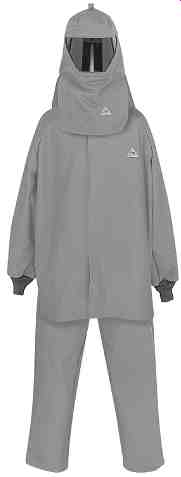
FIG. 2 Flash suit. (Bulwark Protective Apparel.)

FIG. 3 Face shield for flash suit. (Bulwark Protective Apparel.)
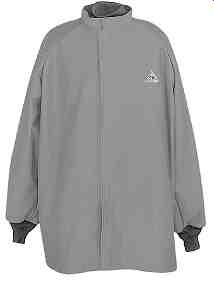
FIG. 4 Flash suit jacket. (Bulwark Protective Apparel.)
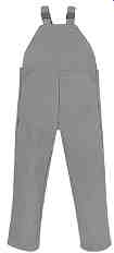
FIG. 5 Flash suit coveralls. (Bulwark Protective Apparel.)
=====
TBL. 6 procedures That Require the Use of Flash Suits
=====
TBL. 7 Work Situations That Require Nonconductive head protection and Eye protection
=====
HEAD AND EYE PROTECTION
Hard Hats
Construction and Standards. In addition to wearing protection from falling objects and other blows, electrical workers should be equipped with and should wear hard hats that provide electrical insulating capabilities. Such hats should comply with the latest revision of the American National Standards Institute (ANSI) standard Z89.1, which classifies hard hats into three basic classes.
1. Class G hard hats are intended to reduce the force of impact of falling objects and to reduce the danger of contact with exposed low-voltage conductors. They are proof tested by the manufacturer at 2200 V phase-to-ground.
2. Class E* hard hats are intended to reduce the force of impact of falling objects and to reduce the danger of contact with exposed higher-voltage conductors. They are proof tested by the manufacturer at 20,000 V phase-to-ground.
3. Class C hard hats are intended to reduce the force of impact of falling objects. They offer no electrical protection.
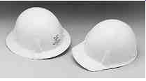
FIG. 6 Hard hats suitable for use in electrical installations. (Mine Safety Appliances
Company.)
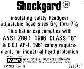
FIG. 7 Hard hat label for a class E hard hat. (Mine Safety Appliances Company.)
Fig. 6 shows two examples of class E (formerly class B) hard hats. Note that a hard hat must be a class G or class E hat to be used in areas where electrical shock may occur.
The label for a class B (now class E) hard hat is shown in Fig. 7.
Use and Care. Electrically insulating class G or E hard hats should be worn by workers any time there is a possibility they will be exposed to shock, arc, blast, mechanical blows, or injuries. Tbl. 7 lists typical working conditions in which workers should be wearing such protection. Note that this table is not comprehensive. Many other electrical activities may expose workers to incident energy levels above 8 cal/cm^2.
All components of the hard hat should be inspected daily, before each use. This inspection should include the shell, suspension, headband, sweatband, and any accessories. If dents, cracks, penetrations, or any other damage is observed, the hard hat should be removed from service. Class G and E hard hats may be cleaned with warm water and soap. Be sure to thoroughly rinse and dry the hat after washing. Solvents and other harsh cleaners should be avoided. Always refer to the manufacturer's instructions for specific cleaning information.
Safety Glasses, Goggles, and Face Shields
The plasma cloud and molten metal created by an electric arc are projected at high velocity by the blast. If the plasma or molten metal enters the eyes, the extremely high temperature will cause injury and possibly permanent blindness. Electrical workers exposed to the possibility of electric arc and blast should be equipped with and should wear eye protection. Such protection should comply with the latest revision of ANSI standard Z87.1 and should be nonconductive when used for electric arc and blast protection.
Flash suit face shields ( Fig. 3) will provide excellent face protection from mol ten metal and the plasma cloud. Goggles that reduce the ultraviolet light intensity ( Fig. 8) are also recommended. Fig. 9 is a photograph of a worker with an insulating hard hat and protective goggles.
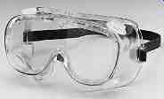
FIG. 8 Ultraviolet-resistant safety goggles. (Mine Safety Appliances
Company.)
Use and Care. Eye and face protection should be worn by workers any time they are exposed to the possibility of electric arc and blast. Tbl. 7 lists typical situations where such protection might be required.
Face protection should be cleaned before each use. Soft, lint-free cloths and warm water will normally provide the necessary cleaning action; however, most manufacturers supply cleaning materials for their specific apparatus.
RUBBER INSULATING EQUIPMENT
Rubber insulating equipment includes rubber gloves, sleeves, line hose, blankets, covers, and mats. Employees should use such equipment when working in an area where the hazard of electric shock exists. This means any time employees are working on or near an energized, exposed conductor, they should be using rubber insulating equipment.
Rubber goods provide an insulating shield between the worker and the energized conductors. This insulation will save the workers' lives should they accidentally contact the conductor. The American Society for Testing and Materials (ASTM) publishes recognized industry standards that cover rubber insulating goods.

FIG. 9 hard hat and goggles. (Mine Safety Appliances Company.)
Rubber Gloves
Description. A complete rubber glove assembly is composed of a minimum of two parts-the rubber glove itself and a leather protective glove. In service, the leather protector fits over the outside of the rubber glove and protects it from physical damage and puncture. Sometimes the glove set will include a sheer, cotton insert that serves to absorb moisture and makes wearing the gloves more pleasant. Fig. 10 shows a typical set of rubber gloves with leather protectors. Caution: rubber gloves should never be used without their leather protectors except in certain specific situations as described later in this section.
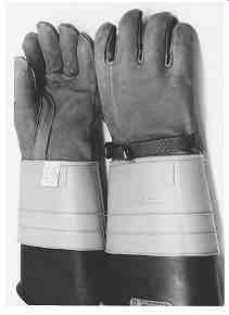
FIG. 10 typical rubber glove set. (W.H. Salisbury and Co.)
====
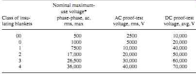
TBL. 8 Rubber Insulating Equipment Classifications, Use Voltages, and
Test Voltages
Class of insulating blankets
Nominal maximum- use voltage* phase-phase, ac, rms, max
AC proof-test voltage, rms, V
DC proof-test voltage, avg, V
====
Construction and Standards. The aStM publishes four standards that affect the construction and use of rubber gloves.
1. Standard D 120 establishes manufacturing and technical requirements for the rubber glove.
2. Standard F 696 establishes manufacturing and technical requirements for the leather protectors.
3. Standard F 496 specifies in-service care requirements.
4. Standard F 1236 is a guide for the visual inspection of gloves, sleeves, and other such rubber insulating equipment.
Rubber gloves are available in six basic voltage classes from class 00 to class 4, and two different types: types I and II. Tbl. 8 identifies each class, its maximum-use voltage, and the root-mean-square (rms) and direct current (dc) voltages that are used to proof-test the gloves. Fig. 11 shows the general design and dimensions of rubber gloves. Rubber gloves are available in the following lengths:
For class 00: 278 mm (11 in), 356 mm (14 in) For class 0: 280 mm (11 in), 360 mm (14 in), 410 mm (16 in), and 460 mm (18 in) For classes 1, 2, 3: 360 mm (14 in), 410 mm (16 in), 460 mm (18 in) For class 4: 410 mm (16 in), 460 mm (18 in) Note that all lengths have an allowable tolerance of ±13 mm (±1/2 in).
Tbl. 9 lists minimum and maximum thicknesses for the six classes of gloves.
In addition to the voltage classes, rubber gloves are available in two different types: type I, which is not ozone resistant, and type II, which is ozone resistant.
All rubber goods must have an attached, color-coded label subject to the minimum requirements specified in Tbl. 10.
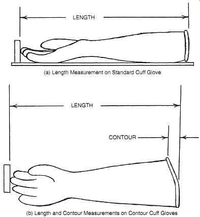
FIG. 11 Dimension measurements for standard and contour cuff rubber
gloves.
(ASTM.) (a) Length Measurement on Standard Cuff Glove; (b) Length and Contour Measurements on Contour Cuff Gloves
When to Use Rubber Gloves. Rubber gloves and their leather protectors should be worn any time there is danger of injury due to contact between the hands and energized parts of the power system. Each of the work situations described in Tbl. 7 should require the use of rubber gloves and their leather protectors.
Rubber gloves should also be worn whenever a worker's hands are closer to an energized conductor than the distance specified by the restricted approach boundary. Some companies require their use when the worker crosses the limited approach boundary.
Although this is ultraconservative, doing so provides enhanced protection. See Section 4 for the definition and calculation methods for the restricted approach boundary.
When to Use Leather Protectors. As stated earlier in this section, leather protectors should always be used over rubber gloves to provide mechanical protection for the insulating rubber. Furthermore, leather protectors should never be used for any purpose other than protecting rubber gloves.
Sometimes the need for additional dexterity may require that the leather protectors not be used. The various industry standards allow such an application in only three situations.
• Class 00 Up to and including 250 V, leather protectors may be omitted for class 00 gloves. Such omission is permitted only under limited-use conditions when small-parts manipulation requires unusually good finger dexterity.
• Class 0 leather protectors may be omitted under limited-use conditions when small- parts manipulation requires unusually good finger dexterity.
• Classes 1, 2, 3, 4
Under limited-use conditions, the leathers may be omitted. However: when the leathers are omitted for these classes, the user must employ gloves rated at least one (1) voltage class higher than normal. For example, if working in a 4160- V circuit without leather protectors, the worker must use class 2 gloves in lieu of class 1 gloves.
Leather protectors should never be omitted if there is even a slight possibility of physical damage or puncture. Also, rubber gloves previously used without protectors shall not be used with protectors until given a thorough inspection and electrical retest.
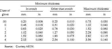
TBL. 9 Rubber Glove Thickness Standard
=====
TBL. 10 labeling Requirements for Rubber Goods
• Color-coded label according to voltage class: class 00-beige,class0-red,class1-white, class 2-yellow, class 3-green, class 4-orange
• Manufacturer's name
• Voltage class (00,0,1,2,3,4)
• Type
• Size(gloves only)
========
How to Use Rubber Gloves. Rubber gloves should be thoroughly inspected and air-tested before each use. They may be lightly dusted inside with pure talcum powder or, better yet, manufacturer-supplied powder. This dusting helps to absorb perspiration and eases putting them on and removing them. Caution: Don’t use baby powder on rubber gloves. Some baby powder products contain additives that can damage the glove and reduce its life and effectiveness. Cotton glove liners worn under the rubber gloves are highly recommended for worker comfort and convenience because they absorb perspiration.
Rubber gloves should be applied before any activity that exposes the worker to the possibility of contact with an energized conductor. As previously stated, any time the worker's hands must be closer to an energized conductor than the restricted approach boundary, rubber gloves must be worn. Be certain to wear the leather protectors with the gloves. Always check the last test date marked on the glove and don’t use it if the last date is more than six months earlier than the present date.
====
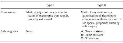
TBL. 11 Types and Special property Specifications of Insulating Rubber
Matting
Type I Type II
Composition
Made of any elastomer or combi- Made of any elastomer or nation of elastomeric compounds, combination of elastomeric properly vulcanized compounds with one or more of the special properties listed by subcategory
Subcategories None A: Ozone resistant B: Flame resistant C: Oil resistant
====
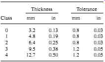
TBL. 12 Thickness Specifications for Insulating Rubber Mats
Thickness Tolerance
Class mm in mm in
=====
TBL. 13 Standard Widths for Insulating Rubber Matting
=====
Rubber Mats
Description. Rubber mats are used to cover and insulate floors for personnel protection.
Rubber insulating mats should not be confused with the nonelectrical rubber matting used to help prevent slips and falls. This type of mat is sold by many commercial retail outlets and is not intended for electrical insulation purposes. Rubber insulating mats will be clearly marked and labeled as such.
Insulating rubber matting has a smooth, corrugated, or diamond design on one surface and may be backed with fabric. The back of the matting may be finished with cloth imprint or other slip-resistant material.
Construction and Standards. The ASTM standard D 178 specifies the design, construction, and testing requirements for rubber matting.
Rubber mats are available in five basic voltage classes, from class 0 to class 4, in two different types, and in three different subcategories. Tbl. 8 identifies each class, its maximum-use voltage, and ac rms and dc voltages that are used to test them. Tbl. 11 identifies each of the types and special properties for insulating mats. Tbl. 12 identifies the thickness requirements for insulating mats. Tbl. 13 identifies the standard widths for insulating rubber matting.
Rubber mats must be clearly and permanently marked with the name of the manufacturer, type, and class. ASTM D 178 must also appear on the mat. This marking is to be placed a minimum of every 3 ft (approximately 1 m).
When to Use Rubber Mats. Employers should use rubber mats in areas where there is an ongoing possibility of electric shock. Because permanently installed rubber mats are subject to damage, contamination, and embedding of foreign materials, they should not be relied upon as the sole or primary source of electrical insulation.
How to Use Rubber Mats. Rubber mats are usually put in place only when required or on a permanent basis to provide both electrical insulation and slip protection. Mats should be carefully inspected before work is performed that may require their protection. Rubber mats should be used only as a backup type of protection. Rubber blankets, gloves, sleeves, and other such personal apparel should always be employed when electrical contact is likely.
Rubber Blankets
Description. Rubber blankets as shown in Fig. 12 are rubber insulating devices used to cover conductive surfaces, energized or otherwise. They come in a variety of sizes and are used any time employees are working in areas where they may be exposed to energized conductors or have a need to isolate themselves from grounded surfaces.
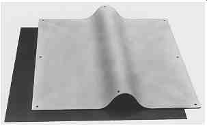
FIG. 12 Typical insulating rubber blanket.
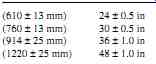
TBL. 14 Standard Blanket Sizes--Length and Width
Construction and Standards. The ASTM publishes three standards that affect the construction and use of rubber blankets.
1. Standard D 1048 specifies manufacturing and technical requirements for rubber blankets.
2. Standard F 479 specifies in-service care requirements.
3. Standard F 1236 is a guide for the visual inspection of blankets, gloves, sleeves, and other such rubber insulating equipment.
Rubber blankets are available in five basic voltage classes (0 to 4), two basic types (I and II), and two styles (A and B). Tbl. 8 identifies each class, its maximum-use volt age, and the ac rms and dc voltages that are used to proof-test the blankets. Tbl. 14 lists standard blanket sizes, and Tbl. 15 lists standard blanket thicknesses.
Type I blankets are made of an elastomer that is not ozone resistant. Type II blankets are ozone resistant. Both type I and type II blankets are further categorized into style A and style B. Style A is a non-reinforced construction, and style B has reinforcing members built in.
The reinforcing members may not adversely affect the insulating capabilities of the blanket.
Blankets have a bead around the entire periphery. The bead cannot be less than 0.31 in (8 mm) wide nor less than 0.06 in (1.5 mm) high. Blankets may have eyelets to facilitate securing the blanket to equipment; however, the eyelets must not be metal.
Rubber blankets must be marked either by molding the information directly into the blanket or by means of an attached, color-coded label. The labeling is subject to the mini mum requirements specified in Tbl. 10. Fig. 13 summarizes the voltage ratings for all rubber goods and illustrates the labels that are applied by one manufacturer.
When to Use Rubber Blankets. Rubber blankets should be used any time there is danger of injury due to contact between any part of the body and energized parts of the power system. Rubber blankets may be used to cover switchgear, lines, buses, or concrete floors.
They differ from mats because they are never permanently installed.
How to Use Rubber Blankets. Rubber blankets should be thoroughly inspected before each use. They may then be wrapped around or draped over metal conductors or buses. When used in either of these ways, they are held in place by using nonconductive blanket buttons or nonconductive "clothespins" that are specially designed for this use. Magnetic blanket buttons, specially designed for this purpose, may be used to hang blankets on metal switchgear frames or switchboards to create an insulating barrier. Rubber blankets are never secured by using electrical plastic or friction tape because when the tape is removed, the face of the blanket is damaged, thereby rendering the blanket unfit for service.
Blankets should be applied before any activity that exposes the worker to the possibility of contact with an energized conductor. Always check the last test date marked on the blanket and don’t use it if the last test date was more than one year earlier than the present date.
TBL. 15 Rubber Blanket Thickness Measurements
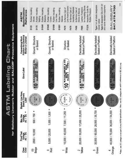
FIG. 13 ASTM labeling chart.
Rubber Covers
Description. Rubber covers are rubber insulating devices that are used to cover specific pieces of equipment to protect workers from accidental contact. They include several classes of equipment such as insulator hoods, dead-end protectors, straight line hose or connector line hose equipped with serrations on the outside of the male end and serrations on the inside of the female connector end designed to hold them together, cable end covers, and miscellaneous covers. Rubber covers are molded and shaped to fit the equipment for which they are intended. None of these devices should ever be taped with electrical plastic or friction tape to hold them in place. If they are taped on, the insulating rubber is damaged or destroyed when the tape is removed. Always secure them with the proper equipment to prevent damage.
Construction and Standards. The ASTM publishes three standards that affect the construction and use of rubber covers.
1. Standard D 1049 specifies manufacturing and technical requirements for rubber covers.
2. Standard F 478 specifies in-service care requirements.
3. Standard F 1236 is a guide for the visual inspection of blankets, gloves, sleeves, and other such rubber insulating equipment.
Rubber covers are available in five basic voltage classes (0 to 4), two basic types (I and II), and five styles (A, B, C, D, and E). Tbl. 8 identifies each class, its maximum-use voltage, and the ac rms and dc voltages that are used to proof-test the covers. Many varieties of rubber covers are available ( Fig. 14). Their size and shape are determined by the equipment that they are designed to cover. Refer to ASTM standard D 1049 for complete listings of the various standard covers.
Type I covers are made of a properly vulcanized, cis-1,4-polyisoprene rubber com pound that is not ozone resistant. Type II covers are made of ozone-resistant elastomers.
Both type I and II covers are further categorized into styles A, B, C, D, and E. Tbl. 16 describes each of the five styles.
Rubber covers must be marked either by molding the information directly into the cover or by means of an attached, color-coded label. The labeling is subject to the minimum requirements specified in Tbl. 10.
When to Use Rubber Covers. Rubber covers should be used any time there is danger of an injury due to contact between any part of the body and energized parts of the power system.
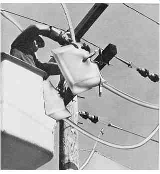
FIG. 14 Typical insulating rubber covers. (W.H. Salisbury and Co.)
====
TBL. 16 Styles of Rubber Covers
Style | Description | A Insulator hoods B Dead-end protectors C line hose connectors D Cable end covers E Miscellaneous covers
====
How to Use Rubber Covers. Rubber covers should be thoroughly inspected before each use. They may then be applied to the equipment that they are designed to cover. Any covers that appear to be defective or damaged should be taken out of service until they can be tested.
Covers should be applied before any activity that exposes the worker to the possibility of contact with an energized conductor. Covers that are used to connect line hose sections should always be used when multiple line hose sections are employed.
Line Hose Description. Rubber insulating line hoses are portable devices used to cover exposed power lines and other energized or grounded equipment, to protect workers from accidental con tact with energized or grounded surfaces such as guy wires, transformer riser taps, or miscellaneous equipment in the immediate work area. Line hose segments are molded and shaped to completely cover the equipment to which they are affixed.
Construction and Standards. The ASTM publishes three standards that affect the construction and use of rubber line hose.
1. Standard D 1050 specifies manufacturing and technical requirements for rubber line hose.
2. Standard F 478 specifies in-service care requirements.
3. Standard F 1236 is a guide for the visual inspection of blankets, gloves, sleeves, and other such rubber insulating equipment.
====
Style Description
A Straight style, constant cross section B Connect end style; similar to straight style with connection at one end C Extended lip style with major outward-extending lips D Same as style C with a molded connector at one end
TBL. 17 Characteristics of the Four Styles of line hose
====
Rubber line hose is available in five basic voltage classes (0 to 4), three basic types (I, II, and III), and four styles (A, B, C, and D). Tbl. 8 identifies each class, its maxi mum-use voltage, and the ac rms and dc voltages that are used to proof-test them.
Type I line hose is made of a properly vulcanized, cis-1,4-polyisoprene rubber com pound that is not ozone resistant. Type II line hose is made of ozone-resistant elastomers.
Type III line hose is made of an ozone-resistant combination of elastomer and thermoplastic polymers. Type III line hose is elastic. All three types are further categorized into styles A, B, C, and D. Tbl. 17 lists the characteristics of each of the four styles.
Rubber line hose must be marked either by molding the information directly into the hose or by means of an attached, color-coded label. The labeling is subject to the minimum requirements specified in Tbl. 10.
When to Use Rubber Line Hose. Rubber line hose should be used any time personnel are working on or close to energized lines or grounded surfaces, or any equipment that could become energized or provide an accidental path to ground.
How to Use Rubber Line Hose. Line hoses should be thoroughly inspected before each use.
They may then be applied to the equipment that they are designed to cover. Any line hose that appears to be defective or damaged should be taken out of service until it can be tested.
Line hose should be applied before any activity that exposes the worker to the possibility of contact with an energized conductor. When more than one section of line hose is used, connecting line hoses should be employed. The line hose should completely cover the line or equipment being isolated.
Rubber Sleeves
Description. Rubber sleeves ( Fig. 15) are worn by workers to protect their arms and shoulders from contact with exposed energized conductors. They fit over the arms and complement the rubber gloves to provide complete protection for the arms and hands. They are especially useful when work must be performed in a cramped environment.
Construction and Standards. The ASTM publishes three standards that affect the construction and use of rubber sleeves.
1. Standard D 1051 specifies manufacturing and technical requirements for rubber sleeves.
2. Standard F 496 specifies in-service care requirements.
3. Standard F 1236 is a guide for the visual inspection of blankets, gloves, sleeves, and other such rubber insulating equipment.
Insulating sleeves are available in five basic voltage classes (0 to 4), two basic types (I and II), and two styles (A and B). Tbl. 8 identifies each class, its maximum-use volt age, and the ac rms and dc voltages that are used to proof-test them.
Type I sleeves are made of properly vulcanized, cis-1,4-polyisoprene rubber compound that is not ozone resistant. Type II sleeves are made of ozone-resistant elastomers.
Style A sleeves are made in a straight, tapered fashion ( Fig. 16). Type B sleeves are of a curved elbow construction ( Fig. 15).
Rubber sleeves are manufactured with no seams. They have a smooth finish and self reinforced edges. Sleeves are manufactured with holes used to strap or harness them onto the worker. The holes are nominally 5/16 in (8 mm) in diameter and have nonmetallic, reinforced edges.
Rubber sleeves must be marked clearly and permanently with the name of the manufacturer or supplier, ASTM D 1051, type, class, size, and which arm they are to be used on (right or left). Such marking shall be confined to the shoulder flap area and shall be nonconducting and applied in such a manner as to not impair the required properties of the sleeve.
A sleeve shall have a color-coded label attached that identifies the voltage class. The labeling is subject to the minimum requirements specified in Tbl. 10. Tbl. 18 shows standard thicknesses for rubber sleeves, and Tbl. 19 lists standard dimensions and tolerances.
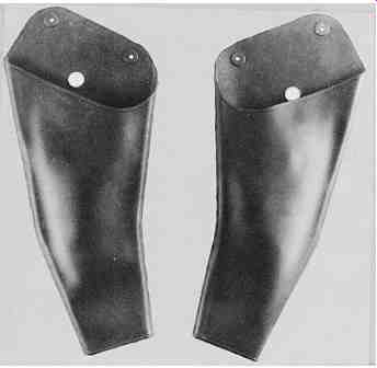
FIG. 15 Insulating rubber sleeves. (W.H. Salisbury and Co.)
When to Use Rubber Sleeves. Rubber sleeves should be used any time personnel are working on or close to energized lines or lines that could be energized. They should be considered any time rubber gloves are being worn and should be required for anyone working around or reaching through energized conductors.
How to Use Rubber Sleeves. Rubber sleeves should be inspected before each use. They may be worn to protect the worker from accidental contact with energized conductors. Be certain to check the last test date marked on the sleeve. If the date is more than 12 months earlier than the present date, the sleeve shall not be used until it has been retested.
======
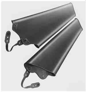
FIG. 16 Style A, straight taper rubber insulating sleeves.
========
Minimum Maximum Class of sleeve mm in mm in
0 0.51 0.020 1.02 0.040 1 0.76 0.030 1.52 0.060 2 1.27 0.050 2.54 0.100 3 1.90 0.075 2.92 0.115 4 2.54 0.100 3.56 0.140
TBL. 18 Standard Thickness for Rubber Insulating Sleeves
=======
TBL. 19 Standard Dimensions and Tolerances for Rubber Insulating Sleeves
======
TBL. 20 Inspection Techniques for Rubber Insulating Equipment
Gloves and sleeves Inspect glove and sleeve surface areas by gently rolling their entire outside and inside surface areas between the hands. This technique requires gently squeezing together the inside surfaces of the glove or sleeve to bend the outside surface areas and create sufficient stress to inside surfaces of the glove or sleeve to highlight cracks, cuts, or other irregularities. When the entire outside surface area has been inspected in this manner, turn the glove or sleeve inside-out and repeat the inspection on the inside surface (now the outside). If necessary, a more careful inspection of suspicious areas can be achieved by gently pinching and rolling the rubber between the fingers. Never leave a glove or sleeve in an inside-out condition. Stretch the thumb and finger crotches by pulling apart adjacent thumb and fingers to look for irregularities in those areas.
Blankets and mats place rubber blankets on a clean, flat surface and roll up tightly starting at one corner and rolling toward the diagonally opposite corner. Inspect the entire surface for irregularities as it’s rolled up. Unroll the blanket and roll it up again at right angles to the original direction of rolling. Repeat the rolling operations on the reverse side of the blanket.
Line hose
Examine the inside surfaces of the insulating line hose by holding the hose at the far end from the lock and placing both hands side-by-side palms down around the hose. With the slot at the top and the long free end of the hose on the left, slowly bend the two ends of the hose downward while forcing the slot open with the thumbs. The hose should be open at the bend, exposing the inside surface. Slide the left hand about a foot down the hose and then, with both hands firmly gripping the hose, simultaneously move the left hand up and the right hand down to pass this section over the crown of the bend for inspection. Slide the right hand up the hose to the left hand.
Hold the hose firmly with the right hand while the left hand again slides another foot down the hose. Repeat the inspection and, in this way, the entire length of hose passes through the hands from one end to the other.
======
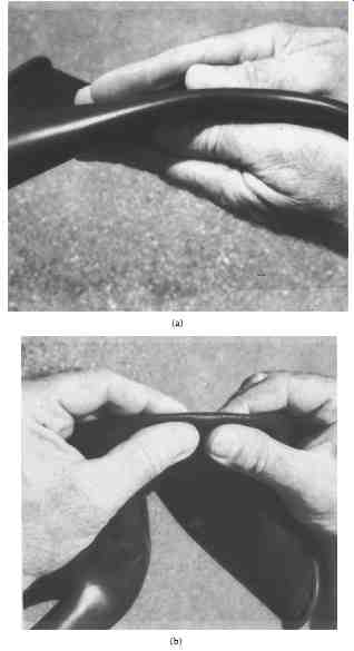
FIG. 17 Inspection of gloves and blanket by rolling. (a) hand rolling;
(b) pinch rolling.
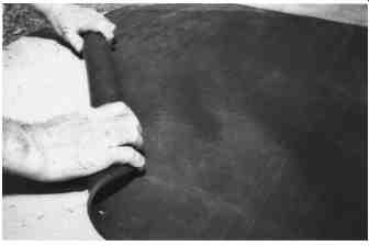
FIG. 18 Inspection of rubber blanket by rolling.
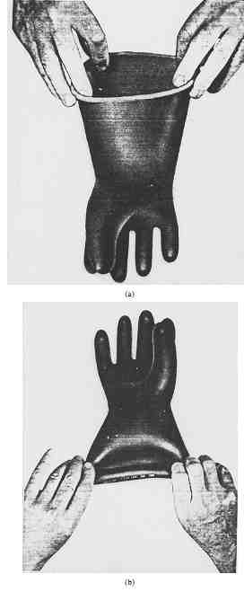
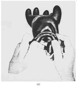
FIG. 19 Inflating rubber gloves by twirling. (a) Grasping; (b) stretching;
(c) twirling.
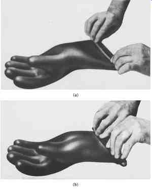
FIG. 20 Inflating rubber gloves by rolling. (a) pressing; (b) rolling.
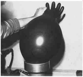
FIG. 21 Mechanical inflation.
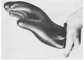
FIG. 22 Visually inspecting inflated rubber gloves.
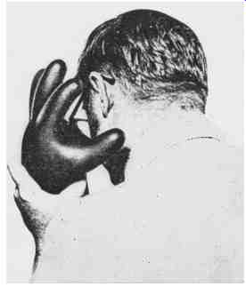
FIG. 23 Inspecting rubber gloves by listening and feeling for air leaks
through pinholes.
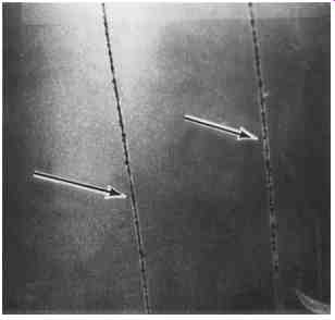
FIG. 24 Scratches.
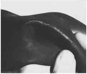
FIG. 25 Age cracks.
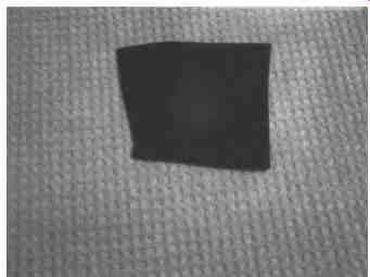
FIG. 26 Chemical bloom.
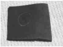
FIG. 27 Color splash.
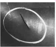
FIG. 28 Cuts.
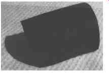
FIG. 29 Depression or indentations.
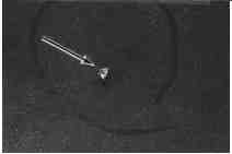
FIG. 30 Embedded foreign material.
In-Service Inspection and Periodic Testing of Rubber Goods
Field Testing. Rubber goods should be inspected before each use. This inspection should include a thorough visual examination and, for rubber gloves, an air test. Tbl. 20 is a synopsis of the inspection procedures defined in ASTM standard F 1236. Rolling is a procedure in which the rubber material is gently rolled between the hands or fingers of the inspector. This procedure is performed on both the inside and outside of the material. Figs. 17 and 18 illustrate two types of rolling techniques.
Rubber gloves should be air-tested before each use. First, the glove should be inflated with air pressure and visually inspected, and then it should be held close to the face to feel for air leaks through pinholes. Note that when air-testing rubber gloves, never inflate them to more than 150 percent of normal glove size. Overinflation will stretch and stress the rubber, thereby destroying its insulating quality. Rubber gloves can be inflated by twirling, by rolling, or by using a mechanical glove inflater. Note that "rolling" in this situation is not the same as the rolling discussed earlier in the description of rubber goods inspection.
To inflate a glove by twirling, grasp the side edges of the glove ( Fig. 19a), gently stretch the glove until the end closes and seals ( Fig. 19b), and then twirl the glove in a rotating motion using the rolled edges of the glove opening as an axis ( Fig. 19c). This will trap air in the glove and cause it to inflate.
Gloves that are too heavy to inflate by twirling may be inflated by rolling. To do this, lay the glove on a flat surface, palm up, and press the open end closed with the fingers ( Fig. 20a). Then while holding the end closed, tightly roll up about 11 2 in of the gauntlet ( Fig. 20b). This will trap air in the glove and cause it to inflate. Gloves may also be inflated by commercially available mechanical inflaters ( Fig. 21). After the gloves are inflated, they may be visually inspected ( Fig. 22) and then checked by holding them close to the face to listen and feel for air leaks through pinholes ( Fig. 23).
Description of Irregularities in Rubber Goods. If damage or imperfections are discovered during inspections, the rubber goods may need to be removed from service. The following are typical of the types of problems that may be discovered.
1. Abrasions and scratches ( Fig. 24). This is surface damage that normally occurs when the rubber material makes contact with an abrasive surface.
2. Age cracks ( Fig. 25). Surface cracks that may look like crazing of glazed ceramics and may become progressively worse. Age cracks result from slow oxidation caused by exposure to sunlight and ozone. They normally start in areas of the rubber that are under stress.
3. Chemical bloom ( Fig. 26). A white or yellowish discoloration on the surface. It’s caused by migration of chemical additives to the surface.
4. Color splash ( Fig. 27). This is a spot or blotch caused by a contrasting colored particle of unvulcanized rubber that became embedded in the finished product during the manufacturing process.
5. Cuts ( Fig. 28). These are smooth incisions in the surface of the rubber caused by contact with sharp-edged objects.
6. Depressions or indentations ( Fig. 29). A shallow recess that exhibits a thinner rubber thickness at the bottom of the depression than in the surrounding areas.
7. Detergent cracks. Cracks that appear on the inside surface of the glove or sleeve. The cracks form around a spot of detergent residue that was not removed during the cleaning and rinsing of the form prior to the dipping process.
8. Embedded foreign matter ( Fig. 30). This is a particle of non-rubber that has been embedded in the rubber during the manufacturing process. It normally shows up as a bump when the rubber is stretched.
9. Form marks. This is a raised or indented section on the surface of the rubber. It’s caused by an irregularity in the form that was used to mold the product.
10. Hard spot ( Fig. 31). A hardened spot caused by exposure to high heat or chemicals.
11. Mold mark ( Fig. 32). A raised or indented section caused by an irregularity in the mold.
12. Scratches, nicks, and snags (Figs. 24, 33, and 34). Angular tears, notches, or chip-like injuries in the surface of the rubber caused by sharp objects such as wire, pointed tools, staples, or other similar sharp-edged hazards.
13. Ozone cracks ( Fig. 35). A series of interlacing cracks that start at stress points and worsen as a result of ozone-induced oxidation.
14. Parting line or flash line. A ridge of rubber left on finished products. They occur at mold joints during manufacturing.
15. Pitting ( Fig. 36). A pockmark in the rubber surface. It’s often created by the rupturing of an air bubble close to the surface during manufacturing.
16. Protuberance ( Fig. 37). A bulge or swelling above the surface of the rubber.
17. Puncture ( Fig. 38). Penetration by a sharp object through the entire thickness of the product.
18. Repair marks ( Fig. 39). An area of the rubber with a different texture. Usually caused by repair of the mold or form.
19. Runs. Raised flow marks that occur on rubber glove fingers during the dipping process.
20. Skin breaks. Cavities in the surface of the rubber. They have filmy ragged edges and smooth interior surfaces. They are usually caused by embedded dirt specks during the manufacturing process.
21. Soft spots. Areas of the rubber that have been soft or tacky as a result of heat, oils, or chemical solvents.
22. Tears ( Fig. 40). A rip through the entire thickness of the rubber. Usually caused by forceful pulling at the edge.
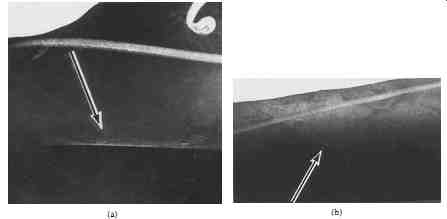
FIG. 32 Mold mark.
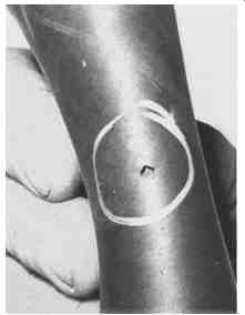
FIG. 33 Nick.
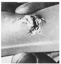
FIG. 34 Snag.
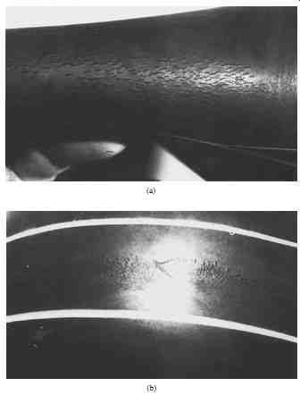
FIG. 35 Ozone cracks.

FIG. 36 pitting.
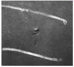
FIG. 37 protuberance.
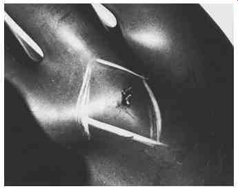
FIG. 38 puncture.
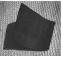
FIG. 39 Repair mark.
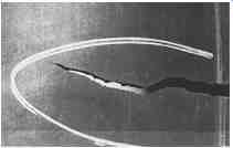
FIG. 40 Tear.
Electrical Testing. Rubber insulating equipment should be electrically tested periodically. Tbl. 21 summarizes the requirements and/or recommendations for such testing. Electrical testing of rubber goods is a relatively specialized procedure and should be performed only by organizations with the necessary equipment and experience.
For detailed testing information, refer to the ASTM standards referenced in Tbl. 21.
Note that all rubber goods are tested at the same voltages dependent upon their class (00, 0, 1, 2, 3, or 4). See Tbl. 8 for a listing of ASTM-required test voltages.
========
TBL. 21 In-service Electrical Tests for Rubber Insulating Goods
product | Maximum test interval, months | ASTM standard | Notes
Gloves 6 F 496 Tested, unused gloves may be placed into service within 12 months of the previous tests without being retested.
Mats - D 178 There is no regulatory requirement for in-service electrical testing of mats. They are tested by the manufacturer when new.
Blankets 12 F 479 Tested, unused blankets may be placed into service within 12 months of the previous tests without being retested.
Covers - F 478 Covers should be retested when in-service inspections indicate a need.
line hose - F 478 line hose should be retested when in-service inspections indicate a need.
Sleeves 12 F 496 Tested, unused sleeves may be placed into service within 12 months of the previous tests without being retested.
========
| Top of Page | PREV: Hazards of Industrial Electricity | NEXT: Electrical Safety Equipment (part 2) | Index |