AMAZON multi-meters discounts AMAZON oscilloscope discounts
<< cont. from part 1
HOT STICKS
Description and Application
Hot sticks are poles made of an insulating material. They have tools and/or fittings on the ends that allow workers to manipulate energized conductors and equipment from a safe distance.
Hot sticks vary in length depending on the voltage level of the energized equipment and the work to be performed. Modern hot sticks are made of fiber glass and/or epoxy glass. Older designs were made of wood that was laminated or treated and painted with chemical-, moisture-, and temperature-resistant materials. Fig. 41 is an example of a simple hot stick fitted with a tool suitable for operation of open-air disconnect switches.
Hot sticks can be fitted with a variety of tools and instruments. The most common fitting is the NEMA standard design shown in Fig. 42 as the standard universal fitting. This fitting allows a variety of tools and equipment to be connected to the hot stick. Fig. 43 shows a voltage tester attached to a hot stick using a standard fitting.
Fig. 42 also shows other attachments and extensions that can be used to increase the usefulness of hot sticks. In addition to the equipment shown in Fig. 42, hot sticks can also be equipped with wrenches, sockets, screwdrivers, cutters, saws, and other such tools.
Hot sticks can also be purchased in telescoping models ( Fig. 44) and so-called shotgun models ( Fig. 45). The telescoping type of hot stick is composed of several hollow, tubular sections that nest inside of each other. The topmost section is first extended and locked in place by means of a spring-loaded button that snaps into a hole. The user of the hot stick extends as many of the sections as are required to accomplish the job at hand. The telescoping hot stick makes very long hot stick lengths available, which then collapse to a small, easy-to-carry assembly.
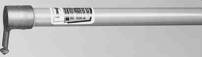
FIG. 41 Typical hot stick. (AB Chance Corp.)
The shotgun hot stick ( Fig. 45) has a sliding lever mechanism that allows the user to open and close a clamping hook mechanism at the end. In this way, the user can attach the stick to a disconnect ring and then operate it. After the switch is operated, the shotgun mechanism is operated to open the hook. The shotgun stick gets its name from its similarity to the pump-action shotgun.
Fig. 46 shows a hot stick kit with several sections and various tools. This type of package provides a variety of configurations that will satisfy most of the day-to-day needs for the electrician and the overhead line worker. The kit includes the following components:

FIG. 42 Various fittings, couplings, and tools for hot sticks.

FIG. 43 Voltage-measuring tool attached to a hot stick.
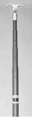
FIG. 44 Telescoping hot stick-shown collapsed. (AB Chance Corp.)
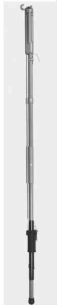
FIG. 45 Shotgun-type hot stick. (AB Chance Corp.)
1. Six 4-ft sections of an epoxy glass snap-together hot stick
2. Aluminum disconnect head for opening and closing switches and enclosed cutouts
3. Nonmetallic disconnect head for use in indoor substations where buswork and switches are in close proximity
4. Clamp stick head for use with 6-in-long eye-screw ground clamps; used to apply and remove safety grounds
5. Tree trimmer attachment with 1½ ft of additional stick and pull rope used to close jaws of the trimmer
6. Pruning saw
7. pistol-grip saw handle for use when tree limbs can be reached and insulation is not required
8. heavy-duty vinyl-impregnated storage case Electricians involved primarily in indoor work might wish to substitute other tools for the tree trimming and pruning attachments.
====
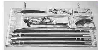
FIG. 46 Typical hot stick kit for electricians and line workers.
======
TBL. 22 Typical procedures
Requiring
Use of hot sticks
Medium voltage and higher
• Voltage measurement
• Any repairs or modifications to energized equipment
All voltages
• Operation of disconnects and cutouts
• Application of safety grounds
====
When to Use
Hot sticks should be used to insulate and isolate the electrician from the possibility of electric shock, arc, or blast. Tbl. 22 identifies the types of procedures for which hot sticks are recommended.
How to Use
The specifics of hot stick use will depend on the task being performed and the location in which the worker is positioned. As a general rule, if hot sticks are being used, the worker should also wear other protective clothing. At a minimum, rubber gloves and face shields should be employed. However, many recommend that flash suits should also be worn, especially when safety grounds are being applied and the worker must approach closer than the flash boundary to do the job.
Before each use, the hot stick should be closely inspected for signs of physical damage, which may affect its insulating ability. If the hot stick is cracked, split, or otherwise dam aged, it should be taken out of service.
Testing Requirements
ASTM standard F 711 requires that manufacturers test hot sticks to very stringent standards before they are sold. Additionally, OShA standards require that hot sticks be inspected and/ or tested periodically. The following should be the minimum:
1. hot sticks should be closely inspected for damage or defects
a. prior to each use.
b. at least every two years.
2. If any damage or defects are noted, the hot stick should be repaired or replaced.
3. hot sticks should be electrically tested according to ASTM standard F 711
a. any time an inspection reveals damage or a defect.
b. every two years.
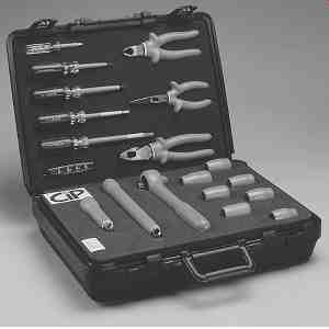
FIG. 47 Insulated tool set. (CIP Insulated Products.)
INSULATED TOOLS
Description and Applicatio
Insulated tools, such as those shown in Fig. 47, are standard hand tools with a complete covering of electrical insulation. Every part of the tool is fully insulated. Only the minimum amount of metallic work surface is left exposed. Such tools are used to prevent shock or arc in the event that the worker contacts the energized conductor.
ASTM standard 1505 defines the requirements for the manufacture and testing of insulated hand tools. Such tools are to be used in circuits energized 50 V ac to 1000 V ac, or 50 V dc to 1500 V dc. The insulated hand tools shown in Fig. 47 are covered with two layers of material. The inner layer provides the electrical insulation and the outer layer provides mechanical protection for the electrical insulation. Insulated tools can also be purchased that have a single, thicker layer of insulation. Either type meets the OShA and NFpA 70E requirements because all are rated for 1000 V ac and 1500 V dc and are tested at 5000 V ac by the manufacturer.
When to Use
Insulated tools should be used any time work is being performed on or near exposed, energized conductors energized at any voltage exceeding 50 V but less than 1000 V ac. They should be inspected before each use.
How to Use and Care For
Insulated tools are used in the same way that ordinary hand tools are used, and all the same precautions should be observed. Avoid using the tools in any application that may damage the insulation. Insulated tools should be kept clean and stored in such a manner as to not cause damage to the insulation. Electrical workers should have a designated tool pouch for insulated tools, so the insulation is not damaged by carrying and storing them in the same pouch as their noninsulated tools are stored and carried in.
BARRIERS AND SIGNS
Whenever work is being performed that requires the temporary removal of normal protective barriers such as panels or doors, barriers and signs should be used to warn personnel of the hazard.

FIG. 48 Barrier tape styles suitable for electrical hazards. (Direct
Safety Supply Co.)
Barrier Tape
Barrier tape is a continuous length of abrasion-resistant plastic tape. It should be a minimum of 2 in wide and should be marked or colored to clearly indicate the nature of the hazard to which employees will be exposed if they cross the tape line. Fig. 48 shows a type of barrier tape suitable for marking and barricading an area where an electrical hazard exists.
Such tape should be yellow or red to comply with Occupational Safety and health Administration (OShA) standards. Generally red tape, or red tape with a white stripe, is the preferred color for such applications. Whatever color is chosen should be a standard design that is used consistently for the same application.
Signs
Warning signs should be of standardized design and easily read. They should be placed in such a way as to warn personnel of imminent hazard. Fig. 49 shows a type of sign suit able for use as an electrical hazard warning.
When and How to Use
General Requirements. Tbl. 23 lists the general procedures for using signs, barriers, and attendants to warn personnel of electrical hazards. Signs should be placed so that they are easily seen and read from all avenues of access to the hazardous area.

FIG. 49 Typical electrical hazard sign. (Ideal Industries, Inc.)
====== TBL. 23 Summary of the Use of Warning Methods
Type of warning-- When to use
Signs
Signs should be placed to warn employees about electrical hazards that may harm them.
Barricades
Barricades should be used to prevent and limit employee access to work areas where they may be exposed to electrical hazards. Such barriers should be made of nonconductive material such as plastic barrier tape.
Attendants
If signs and/or barricades cannot provide a level of safety sufficient to protect employees, attendants shall be placed to guard hazardous areas.
Attendants shall be familiar with the nature and extent of the hazard so as to adequately warn other employees.
=====
Temporary Hazard Barricades. Temporary hazard barricades should be constructed with a striped barrier tape using the following procedure:
1. The tape should be placed so that it completely encloses the hazardous area.
2. The tape should be clearly visible from all directions of approach.
3. The tape should be at a level such that it forms an effective barrier. Approximately 3 ft is suitable.
4. Allow an area of sufficient size to give adequate clearance between the hazard and any personnel outside the hazardous area.
5. If test equipment is being used on equipment inside the hazardous area, the tape should be arranged so that the equipment can be operated outside the area.
6. Don’t use the same style and color of tape for any purpose other than marking temporary hazards.
7. Such a barricaded area should be considered to be the same as a metal enclosure; that is, access is not possible.
8. After the hazard has been eliminated, remove the tape.
SAFETY TAGS, LOCKS, AND LOCKING DEVICES
Safety tags, locks, and locking devices are used to secure and mark equipment that has been taken out of service. They are applied in such a way that the equipment cannot be reenergized without first removing the tags and/or locks. For more information about lockout and tagout procedures, refer to Section 4.
Safety Tags
Safety tags are applied to equipment to indicate that the equipment is not available for service. They are tags constructed of a durable, environment-proof material. They should be of standardized construction and include an "action statement" warning that says Do Not Start, Do Not Open, Do Not Close, Do Not Operate, or other such warning. The tag must also indicate who placed it on the equipment and the nature of the problem with the equipment. Fig. 50 shows tags that are suitable for such an application.
Some manufacturers supply tags with individual employee photographs on them. This type of tag helps to further identify who placed the tag and to personalize the installation.
Tags are to be applied using strong, self-locking fasteners. Nylon cable wraps are suitable for such an application. The fastener must have a breaking strength of not less than 50lb.

FIG. 50 Typical tags suitable for tagout purposes. (Ideal Industries,
Inc.)
Locks and Multiple-Lock Devices
Locks are used to prevent operation of equipment that has been de-energized. They must be strong enough to withstand all but the most forceful attempts to remove them without the proper key. If a lock can be removed by any means other than a bolt cutter or the key that fits it, the lock should not be used.
Standard padlocks are normally applied for lockout purposes ( Fig. 51). Each employee should have a set of padlocks that can be opened only by his or her key. See Section 4 for situations in which a safety lock may be removed by someone other than the individual who placed it.
Departments may also have "group" pad locks that are placed by shift personnel and that are keyed to a departmental key. For example, the operations department may have shift operators who remove and restore equipment from service. Equipment may be removed from service during one shift and later returned to service during another shift.
In such situations, the group lock will be placed by one individual and removed by another. Thus, the group locks will have master keys so that any authorized shift operator can place or remove them.
Multiple-Lock Devices. Sometimes several workers will need to place a lock on one piece of equipment. This often happens when several crafts are working in the area secured by the lock. In these circumstances, a multiple-lock device is used ( Fig. 52). To lock out a piece of equipment, the multiple-lock device is first opened and applied as though it were a padlock. Then the padlock is inserted through one of the holes in the device. The padlock prevents opening of the multiple-lock device, which, in turn, prevents operation of the equipment. The devices shown in Fig. 52a can accommodate up to six locks; however, multiple-lock devices can be "daisy chained" to allow as many locks as required.
The multiple-lock devices in Fig. 52b combine the multiple-lock device with a safety tag. The information required on the tag is written on the tag portion of the device, which is then applied to the equipment.

FIG. 51 Typical padlocks suitable for lock out purposes. (Ideal Industries,
Inc.)

FIG. 52 Multiple-lock devices. (Ideal Industries, Inc.)
Locking Devices
Some equipment, such as wall switches and molded-case circuit breakers, don’t readily accommodate locks. In these instances, when lockout is required, a locking device must be used. Fig. 53a shows locking devices that may be placed over the handle of a molded case circuit breaker and clamped in place. The lock is then installed through the hole left for that purpose. The breaker cannot be operated until the device is removed, and the locking device cannot be removed until the padlock is open.
Fig. 53b is a similar device that mounts on a standard wall switch. The locking device is first attached to the wall switch with the switch faceplate mounting screws. The switch is moved to the off position and the hinged cover of the device is closed. A padlock is placed through the flange supplied for that purpose.
Devices like the wall switch lockout device can be left in place permanently for switches that are frequently locked out. Although the device shown in Fig. 53b can be used to lock the switch in the on position, this practice is not a good safety practice.
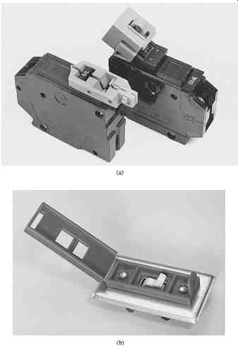
FIG. 53 locking devices.
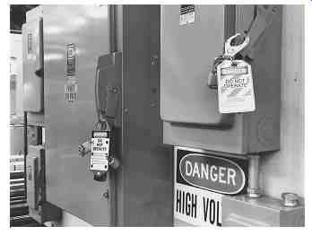
FIG. 54 Typical application of locks, tags, and multiple-lock devices.
When and Where to Use Lockout-Tagout
Equipment should be locked out and tagged out when it’s being serviced or maintained and an unexpected start-up could injure personnel who are working in the area. Thus tags and locks should be placed any time an employee is exposed to contact with parts of the equipment that have been de-energized.
The locks and tags must be applied to all sources of power for the affected equipment.
They must be applied in such a way that the equipment cannot be reenergized without first removing the locks and/or tags. See Section 4 for more complete information on lockout-tagout procedures. Fig. 54 shows locks, tags, and multiple-lock devices being applied to electrical switching equipment.
VOLTAGE-MEASURING INSTRUMENTS
Safety Voltage Measurement
Safety voltage measurement actually involves measuring for zero voltage. That is, a safety measurement is made to verify that the system has been de-energized and that no voltage is present. (See Section 4 for more details.) Because of this, the instruments that are used for safety voltage measurement need only be accurate enough to determine whether or not the nominal system voltage is present at the point of worker exposure.
The instruments discussed in the following sections are intended primarily for safety voltage measurements. Some of them are quite accurate. Contact the individual manufacturers for more specific information.
For various reasons, some authorities prefer a proximity tester over a contact tester, while others prefer a contact tester over a proximity tester. Whichever type is selected, it must be capable of indicating the presence of dangerous voltages and discriminating between nuisance static voltages and actual hazardous voltage sources. Voltage sources. See Section 4 for more info.
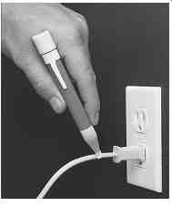
FIG. 55 "AC Sensor" proximity voltage sensor for use on circuits
up to 600 V alternating current. (Santronics, Inc., Sanford, NC.)
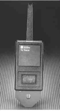
FIG. 56 "TIC" tracer proximity voltage sensor for use on
circuits up to 35,000 V. (TIF Electronics.)
Proximity Testers
Proximity testers don’t require actual metal to-metal contact to measure the voltage, or lack of voltage, in a given part of the system.
They rely on the electrostatic field established by the electric potential to indicate the presence of voltage. Proximity testers will indicate voltage levels through insulation.
They may not provide accurate results when cable is shielded.
Proximity testers don’t indicate the actual level of the voltage that is present.
Rather they indicate the presence of voltage by the illumination of a light and/or the sounding of a buzzer. Figs. 55 through 57 are three different types of proximity detectors for various voltage levels.
Fig. 55 shows a simple neon light proximity tester. The end of the unit is plastic and sized to fit into a standard 120-V duplex receptacle. It requires two AAA flashlight cells to operate. When placed in proximity to an energized circuit, the red neon, located in the white plastic tip, glows.
Fig. 56 shows a proximity tester that uses a combination of audio and visual indicators. When turned on, the unit emits a slow beeping sound that is synchronized to a small flashing light. If the unit is placed close to an energized circuit, the number of beeps per second increases. The light flashes increase in frequency along with the beeps. The higher the voltage and/or the closer the voltage source, the faster the beeps. When the voltage is very high, the beeping sound turns into a steady tone. This unit has a three-position switch. One position turns the unit off, and the two others provide low- and high-voltage operation, respectively. If high voltages are being measured, the unit should be attached to a hot stick. The manufacturer supplies a hot stick for that purpose.
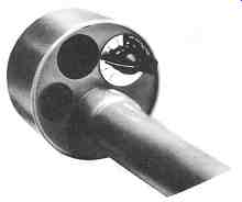
FIG. 57 Audiovisual proximity voltage tester for use in circuits from
240 V to 500 kV. (W.H. Salisbury and Co.)
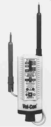
FIG. 58 Safety voltage and continuity tester.
Fig. 57 shows a proximity tester that is similar in some ways to the one shown in Fig. 56. It has both a light and a tone; however, the light and tone are steady when a voltage is sensed above the unit's operational threshold. The unit in Fig. 57 also has a multiposition switch that has an off position, a 240-V test position, a battery test position, and multiple voltage level positions from 4200 V up to the unit's maximum. This unit is shown attached to a hot stick in Fig. 43. It should not be used to measure voltages without the use of a hot stick and/or appropriate rubber insulating equipment.
Contact Testers
Some personnel prefer the use of testers that make actual metal-to-metal contact with the circuit being energized. Such instruments are called contact testers. Contact testers may be simple indicators, but more often they are equipped with an analog or digital meter that indicates actual voltage level. Figs. 58 through 61 illustrate various styles of con tact testers that may be used for safety-related measurements.

FIG. 59 Digital readout contact-type safety voltmeter. (Tegam, Inc.)

FIG. 60 Digital readout multimeter. (Fluke.)
Fig. 58 shows one of the more popular models used for voltages up to 600 V alternating current or direct current. This unit is a solenoid type of instrument. That is, a spring-loaded sole noid plunger is connected to an indicator that aligns with a voltage scale. The distance that the plunger travels is proportional to the voltage level of the measured circuit. The voltage scale is read in volts. The instrument shown in Fig. 58 also indicates continuity and low voltage. It switches automatically between those functions. Note that this style of unit is one of the older, but still popular styles in use for low voltage measurements.
Caution: Because of their solenoid mechanism, these styles are subject to small arcs when contact is made with the measured circuit. This problem is mitigated in some instruments by using test leads equipped with fused resistors. Such resistors not only eliminate the arcing problem but also open in the event that an internal short circuit occurs in the meter. Because of the possible arcing problem, these testers are not allowed in many petrochemical plants or other locations with potentially explosive atmospheres.
Fig. 59 shows a modern, digital read out safety voltmeter. This instrument is suit able for circuits up to 1000 V and is tested to 2300 V. It has an inherently high impedance and often has fused leads; therefore, it’s not prone to arcing when the leads make contact.
The meter should only be used for voltage measurements. It has no continuity or ammeter scales.
Fig. 60 shows a typical digital multimeter. These instruments are in common use by virtually all electricians and electrical and electronic technicians. Such instruments often have voltage ranges well above 1000 V; however, their use in power circuits with voltages above 600 V is not recommended. Care should be taken when using this style of instrument in an electric power circuit. When making a voltage measurement, the user must carefully check to be sure that the instrument is in the voltage mode and that the leads are plugged into the correct jacks.
The instrument shown in Fig. 61 is called a phasing tester because it’s often used to phase two circuits-that is, to check that A phase in circuit 1 is the same as A phase in circuit 2 and so on. Such units are also used for safety-related voltage measurements. The instrument is composed of two high-resistance elements in series with an analog instrument. The resistances are selected in such a way that the meter tracks accurately up to 16 kV. To extend the range of the instrument up to 48 or 80 kV, extension resistors can be added.
Selecting Voltage-Measuring Instruments
Voltage-measuring instruments must be selected based on a variety of criteria. The following sections describe each of the steps that should be used in the selection of voltage measuring instruments.
Voltage Level. The instrument used must have a voltage capability at least equal to the voltage of the circuit to be measured.
Make certain that the manufacturer certifies the instrument for use at that level.
Application Location. Some instruments are designed for use solely on overhead lines or solely in metal-clad switchgear.
Make certain that the manufacturer certifies the instrument for the application in which it will be used.
Internal Short-Circuit Protection. If the measuring instrument should fail internally, it must not cause a short circuit to appear at the measuring probes. Instruments with resistance leads and/or internal fuses should be employed. If an internal fuse opens, always replace it with the identical fuse or one that is recommended by the manufacturer.
Sensitivity Requirements. The instrument must be capable of reading the lowest volt age that can be present. This is from all sources such as backfeed as well as normal voltage supply.
Circuit Loading. The instrument must be capable of measuring voltages that are inductively or capacitively coupled to the circuit. Therefore, it must have a high enough circuit impedance so that it does not load the circuit, thereby reducing the measured voltage to apparently safe levels.
Instrument Condition Before performing voltage measurements, the measuring instrument must be carefully inspected to ensure that it’s in good mechanical and electrical condition.
Case Physical Condition. The case and other mechanical assemblies of the instrument must be in good physical condition and not cracked, broken, or otherwise damaged. Any instrument with a broken case should be taken out of service and repaired or replaced.
Probe Exposure. Only the minimum amount of lead should be exposed on contact-type instruments. This minimizes the chance of accidentally causing a short circuit when the lead contacts more than one conductor at a time. Low-voltage instruments such as those shown in Figs. 58 and 59 have spring-loaded plastic sleeves. Spring loaded sleeves are no longer allowed and have been replaced by fixed plastic sleeves. Probes with spring-loaded sleeves should be replaced.
Lead Insulation Quality. The lead insulation should be closely inspected. If the insulation is frayed, scored, or otherwise damaged, the leads should be replaced before the instrument is used to measure voltage.
Fusing. If the instrument you are using is fused, the fuse should be checked to make certain that it’s of the right size and capability. Instruments used to measure power system voltages should be equipped with high interrupting capacity fuses that will safely interrupt 200,000 A at rated voltage.
Operability. Make certain that the instrument is operable. If it uses batteries, they should be checked before the instrument is placed in service. Check the instrument on a known hot source before it’s taken into the field. If it does not work, take it out of service until it can be repaired or replaced.
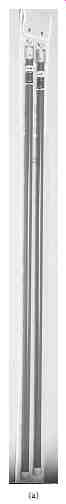
FIG. 61 phasing tester extension handles. (AB Chance Corp.)
=========
TBL. 24 Summary of IEC Meter Categories
Overvoltage category | location of usage | Examples
=========
Low-Voltage Voltmeter Safety Standards
Background. IEC 61010 is a standard that has been developed to define design and usage safety requirements for low-voltage (less than 1000 V ac) meters. The standard applies primarily to contact-type instruments and establishes requirements for meter categories based on the meter's ability to withstand voltage surges such as those experienced in a modern low-voltage power system.
Categories. Tbl. 24 shows the four categories as defined in the standard. For industrial and utility applications, the minimum category used should be category III. If the work to be performed is on the incoming service, incoming substation, or other electrical systems close to the utility system, category IV should be selected.
It’s also important to note that many meters are rated for 600 V while others are rated at 1000 V. The 1000 V rated meters are always the preferred choice from a safety stand point. In many applications, a category III meter rated at 1000 V is superior in surge with stand to a category IV rated at 600 V.
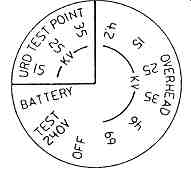
FIG. 62 Selector switch positions for the meter shown in Fig. 57. (W.H.
Salisbury and Co.)
Three-Step Voltage Measurement Process
Since a safety-related voltage measurement is normally made to make certain that the circuit is dead, the measuring instrument must be checked both before and after the actual circuit is read. This ensures that a zero reading is, in fact, zero and not caused by a nonfunctional instrument.
Note that this before-and-after check should be made in addition to the check that is given when the instrument is placed into service from the tool room or supply cabinet. This before-and-after measurement process is called the three step process.
Step 1-Test the Instrument
Before the Measurement. The measuring instrument should be applied to a source that is known to be hot. Ideally this source would be an actual power system circuit; however, this is not always possible because a hot source is not always readily available-especially at medium volt ages and higher.
Because of this problem, manufacturers often have alternative means to check their instruments in the field. Some provide low-voltage positions on their instruments. Fig. 62 shows the switch settings for the instrument of Fig. 57. This instrument may be verified in three different ways:
1. With the switch in the test-240v position, place the instrument head close to a live circuit in excess of 110 V.
2. With the switch in the test-240v position, rub the instrument head on cloth or clothing to obtain a static charge. The unit should indicate periodically.
3. Set the switch to the 35-KV overhead position and place the head close to a spark plug of a running engine.
After the instrument is verified, the battery position can be used to verify the battery supply circuitry and the battery condition.
Fig. 63b shows a test device and setup used to verify the type of instrument shown in Fig. 61. One lead from the test device ( Fig. 63a) is plugged into a special jack mounted on the instrument. The other end is clipped to each of the measuring probes, one at a time. The reading on the instrument meter is used to determine the operability of the test instrument.
Of course, the best way to test an instrument is to check it on a known hot source using the scale position that will be used for the actual measurement.
Step 2-Measure the Circuit Being Verified. The instrument should then be used to actually verify the presence or absence of voltage in the circuit. See Section 4 for a detailed description of how to make such measurements.
Step 3-Retest the Instrument. Retest the instrument in the same way on the same hot source as was used in step 1. Tbl. 25 summarizes the voltage-measuring steps discussed in this section. Because of the extreme importance of voltage measurement, this procedure is repeated in more detail in Section 4.
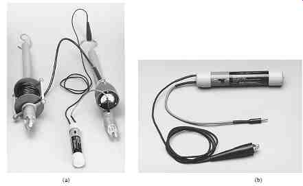
FIG. 63 Field test unit for voltage testers similar to Fig. 61. (AB
Chance Corp.)
=========
Instrument selection • Voltage level
TBL. 25 Voltage-Measurement Instrument Selection and Use
=======
General Considerations for Low-Voltage Measuring Instruments
Most general-purpose multimeters are not designed for power system use. This is certainly true of many of the small units that are available from some major retail companies.
Tbl. 26 lists specific requirements for test instruments used in power system voltage measurement.
SAFETY GROUNDING EQUIPMENT
The Need for Safety Grounding
Even circuits that have been properly locked and tagged can be accidentally energized while personnel are working on or near exposed conductors. For example,
• If capacitors are not discharged and grounded, they could accidentally be connected to the system.
• Voltages could be induced from adjacent circuits. Such voltages can be extremely high if the adjacent circuit experiences a short circuit.
• Switching errors could result in reenergizing of the circuit.
• An energized conductor can fall or be forced into the de-energized circuit, thereby energizing it and causing injury.
• Lightning strikes could induce extremely high voltages in the conductors.
Employees who are working on or near such exposed conductors could be severely injured from shock, arc, or blast that results when the conductors are accidentally energized. Because of this, safety grounding equipment should be employed as one additional safety measure when employees must work near exposed conductors.
Whenever possible, safety grounds are applied to create a zone of equal potential, or "equipotential" zone of protection, around the employee. This means that the voltage is equal on all components within reach of the employee. Correct methods for applying safety grounds are discussed more fully in Section 4.
=========
TBL. 26 Checklist for low-Voltage Measuring Equipment
Instrument should be certified for use in electric power systems leads should be of proper design
Secured permanently to instrument
Fully insulated probes with minimum metallic exposure
Insulation rated for voltage of circuits to be measured Internal fusing capable of interrupting fault current if short circuit occurs high-resistance measurement to minimize arcing at probe tips Single-function (voltage readings) instrument preferred
If a multimeter is used, the resistance and current measurement circuits must be adequately fused
Auto-voltage detection is desirable Instrument insulation levels should be rated for voltage of the circuits to be measured Instrument should be the correct category for the application per IEC 61010
======
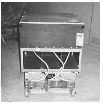
FIG. 64 Front view of a 15-kV grounding switch. (UNO-VEN Refinery,
Lemont, IL.)
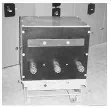
FIG. 65 Rear view of a 15-kV grounding switch. (UNO-VEN Refinery, Lemont,
IL.)
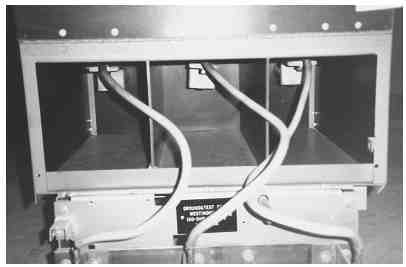
FIG. 66 Close-up of jumper connections for 15-kV grounding switch.
(UNO-VEN Refinery, Lemont, IL.)
Safety Grounding Switches
Grounding switches are specially manufactured units designed to replace a circuit breaker in medium-voltage metal-clad switchgear. The switch rolls into the space normally occupied by the breaker, and the switch stabs connect to the bus and line connections that normally connect to the breaker stabs. Figs. 64 through 66 show various views of a typical grounding switch.
Two different varieties of grounding switches are in common use. One type of switch has two sets of disconnect stabs: one set connects to the bus phase connections, and the other connects to the line connections. The other type of switch has only one set of stabs, which can be moved to connect to either the bus or the line side of the switchgear connections.
For either variety of grounding switch, internal connections can be made to electrically ground the bus, the line, or both sides of the switch. Thus the switch grounds the circuit at the source.
Ground switches should be used very carefully and should not be relied on for 100 percent personal safety protection. Except in metal-clad switchgear, grounding switches cannot create a zone of equalized potential. Safety grounds (see next section) should be employed when secure personal protection is required.
Safety Grounding Jumpers
General Description. Safety grounding jumpers (also called safety grounds) are lengths of insulated, highly conductive cable with suitable connectors at both ends. They are used to protect workers by short-circuiting and grounding de-energized conductors. So if a circuit is accidentally energized, the safety grounds will short-circuit the current and protect the workers from injury. Safety grounds also drain static charges and prevent annoying or dangerous shocks. Fig. 67 illustrates a typical safety ground.
Notice that the safety ground is composed of three major component parts: the clamp, the ferrule, and the cable. The entire assembly must be capable of withstanding the enormous thermal and magnetic forces that are applied when the circuit to which the jumper is applied becomes energized. The construction of safety grounds and their component parts is regulated by ASTM standard F 855.
Clamps. Clamps serve to connect the grounding jumper to the cable or bus system that is being grounded.
ASTM standard F 855 defines three types of clamps (I, II, and III). Each of the three types is available in two basic classes (A and B). Tbl. 27 describes the basic types and classes of clamps.
====
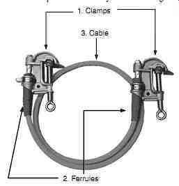
FIG. 67 A typical safety ground with component parts marked. (W.H.
Salisbury and Co.)
2. Ferrules
3. Cable
1. Clamps
======
TBL. 27 Types and Classes of Grounding Jumper Clamps
Type I
Clamps for installation on de-energized conductors equipped with eyes for installation with removable hot sticks
Type II Clamps for installation on de-energized conductors equipped with permanently mounted hot sticks
Type III Clamps for installation on permanently grounded conductors of metal structures; these clamps are equipped with tee handles, eyes, or square or hexagon head screws, or both;
Class A Clamps equipped with smooth contact surfaces;
Class B Clamps equipped with serrated, cross-hatched, or other means used to abrade or bite through corrosion products on the conductor to which the jaw is clamped
Source: From ASTM standard F 855.
====
Types I and II are used to connect the grounding jumper to the actual de-energized conductor. Type II has hot sticks that are permanently mounted to the clamp, and type I has only rings to which shotgun-type hot sticks can be connected. Type III clamps are used for connection to ground bus, tower steel, grounding clusters, and other such permanently grounded points. Fig. 68a to c illustrates the three types of grounding clamps.
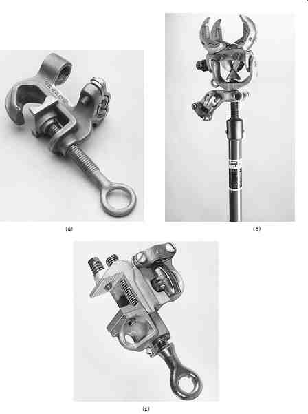
FIG. 68 ASTM type I, II, and III clamps. (a) Type I clamp; (b) type
II clamp; (c) type III clamp. (AB Chance Corp.)
Each type of clamp can be purchased with either non-serrated (class A) or serrated (class B) jaws. Regardless of which type of jaw is purchased, the conductor surfaces should be thoroughly cleaned before application of the clamp. The class B jaws provide additional assurance that adequate electric contact will be made by biting through surface corrosion or dirt.
Clamps are available in seven ASTM grades depending on the short-circuit capability of the circuit to which they will be connected. Tbl. 28 is taken from ASTM standard F 855 and identifies the seven grades and their associated electrical and mechanical characteristics.
Ferrules. Ferrules are used to connect the jumper cable to the clamp. ASTM standard F 855 identifies six basic types of ferrule as described in Tbl. 29. Fig. 69a through d illustrates each of the six basic types.
In addition to types, ferrules are manufactured in seven grades depending upon the short circuit currents that they are designed to withstand. Tbl. 30 shows the electrical and mechanical characteristics for the seven grades of ferrule. Tbl. 31 shows the physical specifications for grounding cable ferrules. Of course, ferrules must be attached to the clamp with a mechanically and electrically secure type of termination. Tbl. 32 lists the ASTM standard types of terminations between ferrules and grounding clamps.
Cables. The cables used for grounding jumpers are specified in three basic types (I, II, and III) as illustrated in Tbl. 33. Note that the insulation can be of any color; however, most manufacturers use yellow, black, or clear insulation. Clear insulation has the advantage of allowing easy visual inspection to detect signs of conductor fusing after severe short circuits. Clear insulation, however, is sometimes sensitive to ultraviolet degradation. yellow insulation has the advantage of being easily visible and indicating a potentially hazardous condition. Black insulation, while acceptable, can be easily mistaken for a normal conductor.
Clear or yellow insulation is the preferred choice for grounding jumper cable.
Grounding jumper cable sizes are determined by the amount of available short-circuit current that is present in the part of the system to which they are being applied. Tbl. 34 lists the maximum current ratings and the size of cable required by ASTM standards.
Tbl. 34 also identifies the current ratings for commercially manufactured, complete jumpers described in the next section.
Complete Jumpers. While some users make their own safety ground jumpers using the ASTM specifications and buying the individual components, most prefer to buy a completely preassembled jumper set as illustrated in Fig. 70. The jumper illustrated in Fig. 70 is designed for use on live-front pad-mount underground distribution (UD) switchgear and transformers. It’s rated at 15,000 A for 30 cycles and 21,000 A for 15 cycles.
It has a three-way terminal block assembly, four bronze body grounding clamps, and three 6-ft lengths of 2/0 clear jacketed copper cable.
Many types of jumpers are available from the manufacturer's stock, and many more types can be quickly assembled by the manufacturer for specific applications.
Selecting Safety Grounding Jumpers
The selection of grounding jumpers may be performed with a relatively simple four-step process.
Short-Circuit Capacity. Determine the maximum short-circuit capability at each typical grounding location. From this information, the size of the cable can be determined from Tbl. 34. (Tbl. 34 is the same as Table 5 in ASTM standard F 855.) Note that in selecting the cable size, it’s perfectly acceptable to use smaller sizes of cable such as 2/0 and then double the cables when required for higher short-circuit duties.
TBL. 28 Grounding Clamp Ratings: Grounding clamp torque strength, min -- Short-circuit properties
=====
Type I Compression ferrule; cylindrical and made for installation on cable stranding by compression Type II Solder ferrule is tubular and made for installation on cable stranding with solder Type III plain stud shrouded compression ferrule with a stepped bore that accepts the entire cable over the jacket Type IV Threaded stud shrouded compression ferrule with stepped bore that accepts entire cable over jacket and has male threads at forward end Type V Bolted shrouded compression ferrule with internal threads and a bolt at forward end Type VI Threaded stud compression ferrule with male threads at forward end
TBL. 29 Types of Ferrules for Use on Safety Ground Jumpers
====
Grounding Clamps. Grounding clamp types and styles must be determined for each conductor size and shape where grounding jumpers may be applied. If cable and/or bus is expected to be corroded and difficult to clean, serrated jaw clamps should be specified.
Remember to specify clamps for both the conductor and the ground end of the grounding set.
Grounding Ferrules. Selection of the grounding ferrules is based on the cable size and material and the cable termination style of the grounding clamp(s). Aluminum or copper plated ferrules should be used with an aluminum clamp and copper cable. Bronze clamps should be used only with copper ferrules and copper cables. Some manufacturers simplify the ferrule selection by employing only one ferrule and cable termination design.
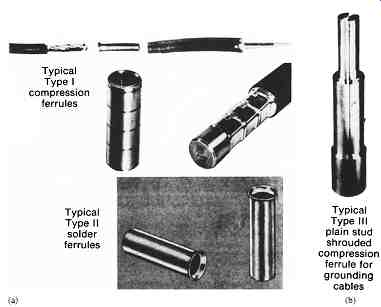
FIG. 69 ASTM types I, II, III, IV, V, and VI ferrules.
====
TBL. 30 Grounding Cable Ferrule Ratings Continuous current
Short-circuit properties*-Symmetrical kA rms, 60 hz
Withstand rating Ultimate rating/capacity†
====
TBL. 31 Grounding Cable Ferrule physical Specifications Note: Inspection or vent holes are optional for types III, IV, V, and VI.
====
TBL. 32 Grounding Cable Ferrules and Compatible Grounding Clamp Terminations
====
Complete Jumper Specification. To simplify the selection of grounding sets, the user may first determine the short-circuit capacity and conductor size and shape, and then refer the design of the jumper to the manufacturer. Most manufacturers have a variety of stock grounding jumpers and will design and build special systems on an as-needed basis.
Installation and Location
The actual procedures and methods for the installation of safety grounds are discussed in detail in Section 4. In general the following rules apply:
1. Always make a three-step voltage measurement, where the tester is tested on a live circuit before and after the actual measurement, to verify the system is dead before installing safety grounds.
2. Grounds should be installed in such a way that they equalize the voltage on all equipment within reach of the worker. This equipotential grounding method is illustrated in Section 4.
3. When possible, safety grounds should be applied on both sides of the work area.
Generally, the more grounding points, the better.
4. Application of safety grounds is considered to be a procedure with more than a normal risk of electric arc. Always wear face shields, rubber gloves, and arc protection rated for the maximum incident energy present at the location where the grounds are being installed.
5. Safety grounds should be applied on systems of any voltage level to add additional protection for personnel when the system is out of service and conductors are exposed.
Systems of 480 V and higher should always be safety-grounded when locked and tagged. lower-voltage systems may be safety-grounded on an as-needed basis.
6. Of course, if the nature of the work precludes the use of safety grounds, they should not be applied. For example, the measurement of insulation resistance cannot be done when safety grounds are installed.
=====
TBL. 33 Cable Types for Use on Safety Ground Jumpers
Type I Cables with stranded, soft drawn copper conductor with 665 or more strands of #30 American Wire Gauge (AWG) (0.0100 in) or #34 AWG (0.0063 in). Flexible elastomer jackets rated for installation and continuous service at temperatures from -40°F (-40°C) through +194°F (90°C).
Type II Cables with stranded, soft drawn copper conductor with 133 wires or more for size #2 or 259 wires or more for size 1/0 and larger. Flexible elastomer jackets rated for installation and continuous service at temperatures from -13°F (-25°C) to +194°F (+90°C).
Type III Cables with stranded, soft drawn copper conductor with 665 or more #30 AWG (0.0100 in). Flexible thermoplastic jackets rated for installation and continuous service at temperatures ranging from +14°F (-10°C) to +140°F (+60°C). Caution: The use of type III jacketed cables is restricted to open areas or spaces with adequate ventilation so that fumes that could be produced by overheating the jacket during a short-circuit fault on the cable can be dispersed.
=====
TBL. 34 Grounding Jumper Ratings Short-circuit properties*
Withstand-rating symmetrical
Ultimate capacity
kA rms, 60 hz symmetrical kA rms, 60 hz
=====
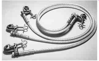
FIG. 70 Commercially manufactured safety ground jumper. (AB Chance
Corp.)

FIG. 71 Standard protection schemes for 120-V circuits. Molded-case
breaker; Hot lead Neutral Ground Duplex outlet

FIG. 72 Standard 120-V supply with ground-fault circuit interrupter.
(AB Chance Corp.)
GROUND-FAULT CIRCUIT INTERRUPTERS
Operating Principles
Most 120-V circuits are fed from standard thermal-magnetic molded-case circuit breakers.
The circuit is similar to that shown in Fig. 71. In this configuration, the only protection from overcurrent is the circuit breaker, which requires a minimum of 15 A to even begin operation. Clearly, if a human being contacts the 120-V circuit, the circuit breaker won’t operate unless a minimum of 15 A flows. Even then, it will operate slowly. Since current levels as low as 10 to 30 mA can be fatal to human beings, such installations are clearly not effective for personnel protection.
Fig. 72 shows a diagram of a safety device that has been in use since the late 1960s.
This device, called a ground-fault circuit interrupter (GFCI), has a current transformer that encloses the hot and the neutral lead. The resulting output of the current transformer is proportional to the difference in the current between the two leads.
To understand its operation, consider what happens when a normal load is attached to the duplex outlet of Fig. 72. Under such circumstances, all the current that flows through the hot wire will go to the load and return to the source on the neutral wire. Since the currents on the hot wire and the neutral wire are equal in magnitude and out of phase by 180°, the output from the GFCI current transformer will be zero and the GFCI won’t operate.
Now consider what happens when a grounded person contacts the hot wire downstream of the GFCI. Under these circumstances, current will flow from the hot wire through the person and will return on the ground wire. Because of this, the currents on the hot wire and the neutral wire won’t be equal. The current transformer will produce an output to the sensor that will, in turn, cause the GFCI breaker contacts to open.
This operation occurs instantaneously, that is, with no intentional time delay. The circuit is disconnected very quickly and the person is spared the long-duration shock. While a GFCI does not guarantee the complete safety of personnel, it’s set sensitively enough to save the life of the person an overwhelming percentage of the time.
Ground-fault circuit interrupters are set to trip when the difference between the hot lead and the neutral lead exceeds 5 mA ± 1 mA. They open typically in less than 25 milliseconds.
GFCIs are sometimes built into low-voltage circuit breakers. They may also be equipped with AFCI capabilities. For more information on AFCIs, see the Arc-Flash Circuit Interrupters section later in this section.
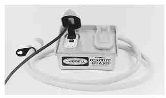
FIG. 73 portable ground-fault circuit interrupter. (Direct Safety Supply
Co.)
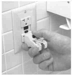
FIG. 74 Receptacle and GFCI tester. (Ideal Industries, Inc.)
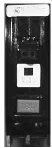
FIG. 75 AFCI breaker
Applications
The National Electrical Code (NEC) specifies locations that require the use of GFCIs.
These locations include bathrooms, swimming pool outlets, and temporary power supplies for construction work. Refer to the most recent edition of the NEC for a detailed list of these requirements.
At a minimum, GFCI receptacles should be used in portable power cords used for temporary construction power during electrical system and other types of industrial work.
Fig. 73 shows a typical GFCI suitable for such use.
Ground-fault circuit interrupters should be tested before each use. In addition to being visually inspected to check for frayed insulation and a damaged case, the GFCI circuit should be tested for proper operation. This test can be easily performed using a simple test device like that shown in Fig. 74. This device plugs into the duplex receptacle. When the receptacle is energized, the user can observe the lights on the end, which will display in a certain pattern if the wiring to the receptacle is correct. The user then presses the test button and an intentional 5-mA ground is placed on the hot wire. If the GFCI is functional, it will operate and open the circuit. The user can then reset the GFCI and put it into service.
Most GFCIs have built-in test buttons. Pressing this button places a resistor between the hot lead and the neutral. The hot lead connection is made ahead of the internal CT and the neutral lead is made after it. This unbalances the current flow and causes the GFCI to trip.
Permanently installed GFCIs should be tested at least once per month. Temporary GFCIs, such as those in extension cords, should be tested prior to each use.
ARC-FAULT CIRCUIT INTERRUPTERS
Thousands of fires are caused each year by electrical wiring failures.
Arcing faults are among the major sources of these failures. Arc fault circuit interrupters (AFCI) are used to detect the existence of an arcing fault and quickly open to clear the problem. Most AFCIs are included in the low-voltage circuit breakers that are found in most homes in the United States, Canada, and many other countries.
Fig. 75 is a photo of an AFCI breaker.
Such breakers include both of the normal overcurrent elements found in standard circuit breakers. They also have electronic circuitry that analyzes the current waveform-usually by looking for arc-indicating harmonics or spikes typical to arcing faults or through other methods.
Some AFCIs also include GFCI circuitry and thus provide standard overcurrent, arcing fault, and ground-fault protection.
The National Electrical Code (NFpA 70) requires AFCIs to be used in most rooms in new construction. Major changes in an electrical system will also require that a standard circuit breaker be replaced with an AFCI. It should be noted that AFCIs alone don’t provide much additional personnel protection above that afforded by a regular circuit breaker. True personnel protection is best provided by GFCIs.

FIG. 76 Typical safety electrical one-line diagram (SEOlD).
========
TBL. 35 Information Required to Be Included on Safety Electrical One-line Diagrams Energy sources
All sources of energy in the power system should be included on the SEOlD. This includes the normal sources such as power company connections and generators, as well as possible sources of backfeed such as instrument transformers and foreign voltages brought in for remote-control purposes.
Disconnect devices
The circuit breakers, switches, cutouts, fused disconnects, and any other devices that can be used to control the power system energy.
Note: All energy sources and disconnect devices should be clearly marked with a unique identifying name and/or number. The device itself should be clearly marked with an identical name and/or number.
=====
TBL. 36 Minimum Safety Equipment for Electricians
Note: This listing is for electrical hazards only. Other protection such as fire extinguishers and flash lights should be supplied as required.
========
SAFETY ELECTRICAL ONE-LINE DIAGRAM
One-line diagrams are used in electric power systems for a variety of purposes including engineering, planning, short-circuit analysis, and-most important-safety. The safety electrical one-line diagram (SEOlD) provides a road map for the electric power system.
Fig. 76 is an example of a typical SEOlD. Safety electrical one-line diagrams are used to ensure that switching operations are carried out in a safe, accurate, and efficient manner.
An accurate, up-to-date, legible SEOLD should be available for all parts of the electric power system. Safety electrical one-line diagrams should be accurate, concise, and legible.
1. Accuracy. The SEOlD should be accurate and up to date. Regular revision reviews should be performed on the SEOlD, and any required changes or modifications should be implemented immediately. Personnel should be aware of the review process and should have easy access to suggesting changes on the SEOlD.
2. Concise. Because one-line diagrams are used for a variety of purposes, some facilities put a large amount of information on one diagram. Items such as cable lengths, sizes, and impedances; current transformer ratios; transformer impedances; protective relay logic circuits; and metering circuits are often found on one-line diagrams used for safety and operations. This practice is not acceptable. Tbl. 35 lists the only items that should be included on a one-line diagram. Note that the use of computer-aided drafting systems makes the development of job-specific one-line diagrams quite simple. All equipment shown on the SEOlD should be clearly identified with symbols or nomenclature that is identical to what is physically on the equipment.
3. Legibility. All too often, SEOlDs are allowed to become illegible. They may be sun bleached, or they may simply be the product of an original diagram that has been allowed to become too old. The SEOlD should be easy to read even in subdued lighting.
The SEOlD is the road map for the field electrician. Each electrical worker should have access to the SEOlD for day-to-day switching activities.
THE ELECTRICIAN'S SAFETY KIT
Each electrician should be supplied with a minimum list of electrical safety equipment, as shown in Tbl. 36. This represents the minimum requirement for an electrician's electrical safety. Other equipment should be added on an as-needed basis.
Since electrical protective devices such as circuit breakers and fuses have ratings and capabilities that must be taken into account when installing or replacing them, field personnel should also have complete information about the protective devices in the system.
Tbl. 37 identifies some of those ratings for circuit breakers, and Tbl. 38 covers fuses. A complete coverage of engineering design is beyond the scope of this handbook.
However, field personnel should be very familiar with these ratings and be able to properly select the protective device when a replacement is required. In general, protective devices should always be replaced by an identical device.
=======
TBL. 37 Circuit Breaker Ratings
Rating Meaning Comments Voltage
The maximum voltage of A breaker installed in a system with too high a rating the circuit where the voltage will likely fail. Additionally, the circuit breaker is used maximum amount of current that the breaker can interrupt is based on the system voltage.
Continuous
The maximum continuous Also referred to as frame size.
Current -- current that a circuit rating breaker can carry without overheating Minimum The minimum current required Continuous current and minimum trip rating trip to initiate operation of the may be two entirely different values. For rating protective circuitry. example, a breaker with a 600-A frame size may be equipped with a 50-A protective device.
Interrupting -- The maximum short-circuit
This is the rating that manufacturers put on rating current that an overcurrent the circuit breaker nameplate.
protective device can safely interrupt under standard test conditions Interrupting The maximum current that a
Note that for any given installation, depending capacity circuit breaker can interrupt on the type testing methodology, this value at the specified voltage level may be different from the interrupting rating.
And system X/R ratio This should be taken into account when the circuit breaker is being selected for use in a specific circuit.
========
TBL. 38 Fuse Ratings
Rating Meaning Comments Voltage
The maximum voltage of the circuit Fuses are usually manufactured in different rating where the fuse is applied sizes and configurations depending on the voltage level. For example, a fuse intended for use in a 250-V circuit will normally be shorter than one that is intended for use in a 600-V circuit. Fuse The maximum continuous current Also referred to as continuous current rating.
Rating that a fuse can carry without This is the current that is referred to when tripping we speak of a 10-A fuse or a 600-A fuse.
Interrupting The maximum short-circuit current This is the rating that manufacturers put on rating that an overcurrent protective the fuse label.
Device can safely interrupt under standard test conditions Interrupting The maximum current that a fuse Type testing of fuses is such that the capacity can interrupt at the specified interrupting rating and the interrupting voltage level and system X/R ratio capacity are usually the same value.
Also see: Electrical safety systems
| Top of Page | PREV: part 1 | NEXT: Safety Procedures and Methods | Index |