AMAZON multi-meters discounts AMAZON oscilloscope discounts
Operating Molded-Case Breakers and Panelboards
General Description. Molded-case circuit breakers are designed with a case that completely contains the arc and blast of the interrupted current, as shown in FIG. 18. Such breakers are permanently mounted in individual enclosures or panelboards ( FIG. 19) along with many other such breakers.
Molded-case breakers have a three-position operating handle-open, closed, and tripped. When the operator opens the breaker, he or she does so by moving the operating handle to the open position. Likewise, the close operation is accomplished by moving the handle to the close position.
When the breaker trips via its internal automatic protective devices, the handle moves to the tripped position. The trip position is normally an intermediate position between the full-closed and full-open positions.
After a trip operation, the breaker cannot be operated until the handle is moved forcefully to the open position. This action resets the internal tripping mechanism and reengages the manual operating mechanism.
Operation. Caution: Circuit breakers should not be used for the routine energizing and de-energizing of circuits unless they are manufactured and marked for such purpose. They may be used for occasional or unusual disconnect service.
Table 7 lists the minimum recommended safety equipment to be worn when operating molded-case circuit breakers, and FIG. 20 illustrates the proper position for the operation.
Notice that a backup operator is not required for this procedure; however, secondary assistance is always a good practice. The procedure can be summarized as follows:
1. The operator stands to the side of the breaker and/or panel, facing the panel. The opera tor may stand to either side, depending on the physical layout of the area.
2. The operator grasps the handle with the hand closest to the breaker.
3. The operator turns his or her head away from the breaker and then firmly moves the operating handle to the desired position.
4. If locks or tags are required, they are placed on the breaker using the types of equipment as described in Section 3.
-- TABLE 7 Recommended Minimum Safety Equipment for operating Molded Case Circuit Breakers
• Hard hat-ANSI Z89.1 class e or G
• ANSI Z87.1 safety glasses with side shields
• Flame-resistant work clothing (select using arc-flash calculations)
• hand protection-leather or flame-resistant gloves (do not need to be insulating)
---
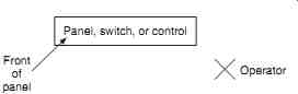
FIG. 20 Proper position for operating molded-case circuit breakers,
enclosed switches, and motor controls (top view).
---
Operating Enclosed Switches and Disconnects
General Description. FIG. 21 shows several basic types of enclosed switches. These devices are used to connect and/or disconnect circuits. Such devices may be load interrupting or non-load-interrupting. If they are non-load-interrupting, they must not be operated when current is flowing in the circuit. If you are uncertain as to whether the switches are load interrupting or not, look on the nameplate or check with the manufacturer. The presence of arc interrupters, such as those in FIG. 21d, is a good indication that the device is intended to interrupt load current.
These switches are operated by moving the handle. In some units, the handle is bolted or locked in place to prevent inadvertent operation. Enclosed switches have a mechanical inter lock that prevents the case from being opened until the handle is in the open position.
Electrically qualified personnel may temporarily defeat the interlock if needed for maintenance or troubleshooting purposes. Such switches should not be operated with the door open when load current if flowing. Be very cautious when opening medium-voltage switches.
Operation. The basic operating procedure for such switches is similar to the procedure given for molded-case circuit breakers. Caution: Switches should not be used to interrupt load current unless they are intended for that purpose. Refer to the manufacturer's information.
Table 8 lists the minimum recommended safety equipment to be worn when operating enclosed switches, and FIG. 20 illustrates the proper position for the operation. Notice that a backup operator is not required for this procedure; however, secondary assistance is always a good practice. The procedure can be summarized as follows:
1. The operator stands to the side, of the switch and/or panel, facing the panel. The opera tor may stand to either side, depending on the physical layout of the area.
2. The operator grasps the handle with the hand closest to the switch.
3. The operator turns his or her head away from the switch and then firmly moves the operating handle to the desired position.
4. If locks or tags are required, they are placed on the switch using the types of equipment described in Section 3.
---
TABLE 8 recommended Minimum Safety Equipment for operating enclosed switches and Disconnects
• Hard hat-ANSI Z89.1 class e or G (as required by voltage level)
• ANSI Z87.1 safety glasses with side shields
• Flame-resistant work clothing (select using arc-flash calculations)
• Rubber gloves with leather protectors (class according to voltage level)
---
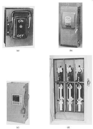
FIG. 21 Various types of low- and medium-voltage, enclosed disconnect
switches. (Courtesy General Electric, Crouse-Hinds Co., and Eaton Corporation,
Cutler Hammer Products.)
---
Operating Open-Air Disconnects
General Description. Open-air disconnects may be manually operated or mechanism operated. Mechanism types ( FIG. 22) are normally installed as overhead devices in medium voltage substations or on pole lines. The switch has an operating handle close to the ground that is used to open or close the contacts. At ground level, a metal platform is often provided for the operator to stand on. This platform is bonded to the switch mechanism and to the ground grid or ground rod to create an equipotential zone of protection for the switch operator. The operator stands on the grid; thus, the operator's hands and feet are at the same electric potential.
Note that the operation of some switches is accomplished by moving the handle in the horizontal plane, while others are moved in a vertical direction.
Manually operated switches are operated by physically pulling on the blade mechanism. In some cases, such as the one shown in FIG. 23, the switch blade is a fuse. The manual operation is accomplished by using a hot stick. Manually operated switches may be located overhead in outdoor installations, or they may be mounted indoors inside metal clad switchgear.
Operation. Recommended protective clothing depends on the type and location of the switch. Table 9 lists the minimum recommended safety equipment for operating over head, mechanism-operated switches such as those shown in FIG. 22. FIG. 24 shows the correct operating position for operating such a switch. Caution: Not all open-air switches are designed to interrupt load current. Do not use a non-load-interrupting switch to interrupt load current.
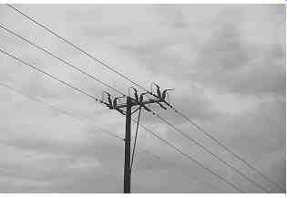
FIG. 22 Mechanism-operated, three-phase, open-air switch. (Courtesy
Alan Mark Franks.)
---
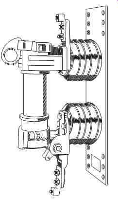
FIG. 23 open-air, fused disconnect switch. (Courtesy General Electric.)
-- TABLE 9 recommended Minimum Safety Equipment for operating overhead, Mechanism-operated Switches
• Hard hat-ANSI Z89.1 class e or G (as required by voltage level)
• ANSI Z87.1 safety glasses with side shields
• Flame-resistant work clothing (select using arc-flash calculations)
• Rubber gloves with leather protectors (class according to voltage level)
----
The basic operating procedure can be summarized as follows:
1. The operator stands on the metal platform (if available).
2. He or she grasps the operating handle firmly with both hands and moves it rapidly and firmly in the open or close direction as required.
3. If locks or tags are required, they are placed on the mechanism using the types of equipment described in Section 3.
---
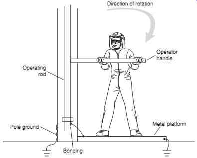
FIG. 24 Correct position for operating an overhead, mechanism-operated switch.
Bonding; Operating rod; Operator handle; Direction of rotation; Metal platform; Pole ground
---
Table 10 lists the recommended equipment for operation of manually operated open air switches. Note that the use of flash suits is dependent on the location of the switch. If the switch is on an overhead construction that is outdoors, the worker may opt to wear flame-resistant clothing instead of a flash suit. Because the operator must use a hot stick to operate this type of switch, he or she must stand directly in front of the switch.
The general operating procedure is as follows:
1. Stand in front of the switch.
2. Carefully insert the hot stick probe into the switch ring.
3. Look away from the switch and pull it open with a swift, firm motion.
4. Since one side of the switch may be hot, locks and tags are not always applied directly to the switch. If the switch is in an indoor, metal-clad enclosure, the lock and tag may be applied to the door of the gear.
-----
TABLE 10 Recommended Minimum Safety Equipment for operating manually operated, open-Air Disconnect switches
• Hard hat-ANSI Z89.1 class e or G (as required by voltage level)
• ANSI Z87.1 safety glasses with side shields
• Flame-resistant work clothing (select using arc-flash calculations)
• Rubber gloves with leather protectors (class according to voltage level)
• Hot stick of proper length with proper fittings
-----
Operating Motor Starters
General Description. With some exceptions, the operation of motor starters is very similar to the operation of low- and medium-voltage gear. FIG. 25 shows a single motor starter in a cabinet suitable for mounting on a wall.
In the motor control center, the starter mounts on a mechanism specially designed for the purpose. In either type of construction, the motor is stopped and started by depressing the appropriate button. The starter also has a fused disconnect or a molded-case circuit breaker that is used to disconnect the motor and its circuitry from the power supply.
Motor starters used in motor control centers connect to the bus and the line via a set of disconnects. When the starter is open, it can be moved toward the front of the cubicle so that it disconnects from the bus and line. This action is referred to as racking. Racking starters is usually accomplished manually. The starter may be completely removed from the motor control center. Note that large medium-voltage contactors may be operated like medium-voltage circuit breakers.
For many types of motor control centers, the front panel provides worker protection from shock, arc, and blast. This means the motor control center is designed to contain arc and blast as long as the door is properly closed and latched.
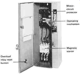
FIG. 25 Combination motor starter in individual metal-clad cabinet.
Closed-Door Operation. The closed-door operation of motor starters is virtually identical to the closed-door operation of low-voltage circuit breakers. Table 6 lists the recommended safety equipment to be used by operators when performing both closed-door and open-door switching on motor starters. Note that both the primary operator and backup operator should be wearing the recommended clothing. The primary operator is the worker who actually manipulates the handle that opens and/or closes the motor starter. The backup operator's responsibility is to support the primary operator in the event there is a problem.
The backup operator may be optional in some facilities.
To operate the starter with a closed door, the following steps apply:
1. While wearing proper hand protection (either rubber insulating gloves with leather protectors or other suitable protection), stand to the side of the motor starter and depress the stop button to properly interrupt the load current.
2. After the motor is stopped, the primary operator stands to the side of the cubicle containing the starter to be operated. The side to which he or she stands should be determined by which side the operating handle is on. If the handle is in the middle, the operator should stand on the hinge side or the handle side of the door, depending on which side is stronger. (refer to the manufacturer.)
3. The primary operator faces away from the gear. Note: If the operating handle of the disconnect has a very tight operating mechanism, the primary operator may face the motor starter to obtain the necessary leverage on the cranking handle.
4. The backup operator stands outside the arc-flash hazard boundary with line of sight to the operator.
5. The primary operator reaches across to the operating handle and operates it to open or close the starter disconnect. Note that the primary operator continues to keep his or her face turned away from the gear. Some operators prefer to use a hot stick or a rope for this operation. This keeps the arms as far as possible from any hazard.
6. If the starter can be racked with the door closed (an unusual configuration), and if the starter is to be racked in or out, the primary operator inserts the racking handle and turns it. Note that starters that are racked manually cannot be racked with the door closed. In this operation, the primary operator will undoubtedly have to face the breaker cubicle.
7. If lockout-tagout procedures are required, the primary operator places the necessary locks and/or tags.
Open-Door Operation. Refer to Table 6 for a minimum listing of safety equipment for this operation. If the door must be open for racking the starter, the following steps should be observed:
1. The motor is stopped as described earlier under closed-door operation.
2. The primary operator opens the cubicle door and racks the starter to the desired position.
3. If lockout-tagout procedures are required, the primary operator places the necessary locks and/or tags.
ENERGY CONTROL PROGRAMS
An energy control program is a procedure for the proper control of hazardous energy sources. It should include a listing of company-approved steps for the proper and safe energizing and de-energizing of energy isolation devices as well as general company policy statements on preferred methods of operation. Energy control programs fall into two categories-general and specific.
General Energy Control Programs
Overview. A general energy program is one that is inherently generic in nature. Its steps are broad-based and designed in such a way that the program can be used as a procedure for a wide variety of equipment types. General energy control programs should be used only when the equipment being isolated meets all the following criteria:
• The equipment can be disabled, so it has no potential for the release of stored or residual energy after shutdown.
• The equipment is supplied from a single energy source that can be readily identified and isolated.
• The equipment is completely de-energized and deactivated by the isolation and locking out procedure.
• No employees are allowed to work on or near the equipment until it has been tagged and locked. (See the lockout-tagout section later in this section.)
• A single lockout device will achieve a locked-out condition.
• The isolating circuit breakers or switches are under the exclusive control of the employee(s) who placed the lock and tag.
• De-energizing and working on the equipment does not create a hazard for other employees.
• There have been no accidents involving unexpected activation or reenergization of the equipment during previous servicing.
Specific Energy Control Programs
When a part of the system or piece of equipment does not meet all the criteria laid out in the overview to this section, a specific energy control program should be written. Although the procedures will vary depending on the specifics of the installation, at a minimum the program should include the following information:
• The description of the system and/or equipment that will be de-energized.
• Any controls, such as motor starter push buttons, that exist on the equipment.
• The voltages and short-circuit capacities of the parts of the system that will be de-energized.
• The circuit breakers, switches, or contactors that are used to de-energize the system.
• The steps that must be used to de-energize the system. The steps should include:
1. The methods and order of operation of the circuit breakers, switches, and so on.
2. Any special requirements for the lockout-tagout procedure.
3. Special notifications and safety requirements.
• Reenergizing requirements and procedures.
Basic Energy Control Rules
• The safest and most secure method to protect personnel from the electrical hazard is to de-energize the conductors that they must work on or near. De-energization is the preferred method.
• If conductors cannot be de-energized, safety equipment and safety-related work practices must be used to protect personnel exposed to the energized conductors.
• Before personnel are allowed to work on or near any exposed, de-energized conductors, the circuit breakers and/or disconnect switches must be locked and tagged to prevent their inadvertent operation.
• All personnel should be instructed to never operate or attempt to operate any circuit breaker and/or disconnect switch when it is tagged and/or locked.
• Only authorized, qualified, and trained personnel should be allowed to operate electrical equipment.
• Locks and tags should be removed only by the personnel that placed them. Two exceptions may apply under the following situations:
1. If the worker who placed the lock and tag is not available, his or her lock and tag may be removed by a qualified person who is authorized to perform such an action. This procedure is often called bypassing control as the person who removes the lock and tag is, in fact, bypassing the authority (control) of the person whose tag is being removed. If this operation is performed, the employees that had the lockout-tagout applied must be properly informed that their lockout-tagout has been violated and removed before they are allowed to return to work on the property.
2. Some facilities may authorize the concept of a group lock. A group lock is placed by an authorized shift worker, such as the shift operator, and may be removed by another authorized shift worker. This activity should not be used to prevent any employee from placing his or her tag and lock on energy-isolating devices that may feed conductors that they must work on or near.
De-energizing Equipment. The general energy program for de-energizing equipment should include the following steps:
1. Before beginning the process, carefully identify the voltage levels and incident energy levels of the portion of the system that will be de-energized. This information serves to establish the level of the hazard to all personnel.
2. Notify all employees who will be affected by the de-energization that the system is to be de-energized.
3. Perform necessary checks and inspections to ensure that de-energizing the equipment will not introduce additional safety hazards, for example, de-energizing safety-related ventilation systems.
4. Using properly rated load-interrupting devices and proper operating instructions, shut down all processes being fed by the electric system that is to be de-energized.
5. Open the appropriate circuit breaker and/or switch.
6. Rack the circuit breaker away from the bus if it is of the type that can be manipulated in this manner.
7. Release stored energy from springs, hydraulic systems, or pneumatics.
8. Discharge and ground any capacitors located in the de-energized portions of the system.
9. Apply tags and/or locks.
10. Attempt to operate the breaker and/or switch to make certain that the locks are preventing operation. If a motor starter is involved, press the start button to make certain the motor will not start.
11. Measure the voltage on the conductors to which employees will be exposed, at the point where they will be exposed.
12. Notify personnel that the system is safely de-energized, locked, and tagged.
Reenergizing Equipment. Reenergization of some systems is more hazardous than de-energization. While the equipment has been out of service, personnel have grown used to its de-energized voltage status. In addition, tools and/or other equipment may have been inadvertently left on or near exposed conductors.
Because of these factors, the same type of rigorous steps should be followed during reenergization.
1. All personnel should be notified that the system is to be reenergized and warned to stay clear of circuits and equipment.
2. A trained, qualified person should conduct all tests and visual inspections necessary to verify that all tools, electric jumpers, shorts, grounds, and other such devices have been removed and that the circuits are ready to be reenergized.
3. Close and secure all cabinet doors and other safety-related enclosures.
4. Because the tests and inspections may have required some time, the personnel warnings should be repeated.
5. Locks and tags should be removed by the personnel that placed them.
6. If breakers were racked into disconnected positions, they should be racked in the connected position.
7. Make final checks and tests, and issue final warnings to all personnel.
8. Reenergize the system by reconnecting and closing circuit breakers and switches. These operations are normally carried out in the reverse order of how they were opened.
Procedures Involving More Than One Person. When more than one person is required to lock and tag equipment, each person will place his or her own personal lock and tag on the circuit breakers and/or switches. The placement of multiple locks and tags on equipment is often called ganging. Since few circuit breakers or switches have the ability to accept multiple locks and tags, this procedure can take one of two common approaches.
1. A multiple-lock hasp may be applied to the breaker or switch. Such hasps will accept up to six locks. If more than six locks are required, multiple-lock hasps may be cascaded. See fig. 3.52 for examples of such hasps.
2. A lockbox may be used. In such an operation, the lock is applied to the breaker or switch and the key is then placed inside the lockbox. The lockbox is then secured by the use of a multiple-lock hasp. This approach is used when the presence of many locks on the switch or breaker might cause operational problems.
After the work has been completed, each employee removes his or her lock from the lockbox. The key for the lock is retrieved and the lock can then be removed by the person who placed it.
LOCKOUT-TAGOUT
Definition and Description
Tags are used to identify equipment that has been removed from service for maintenance or other purposes. They are uniquely designed and have clear warnings printed on them instructing personnel not to operate the equipment. Locks are applied to de-energized equipment to prevent accidental or unauthorized operation. Locks and tags are normally applied together; however, some special circumstances may require the use of a tag without a lock and/or a lock without a tag. See Section 3 for a detailed description of the construction of safety locks and tags.
Employers should develop a written specification that clearly defines the lockout-tagout rules for the facility. This specification should be kept on file and reviewed periodically to ensure that it is kept up to date. The following sections define the key elements that should be included in the specification.
When to Use Locks and Tags
Locks and tags should be applied to open circuit breakers, switches, or contactors whenever personnel will be exposed to the conductors that are normally fed by those devices. The application of the tags will warn and inform other employees that the equipment is not available for service, who applied the tag, and why the tag was applied. The lock will prevent the operation of the breaker, switch, or contactor so that the circuit cannot be accidentally reenergized.
Minor inspections, adjustments, measurements, and other such servicing activities that are routine, repetitive, and integral to the use of the equipment do not require the placement of locks and tags unless one of the following conditions exist:
1. Guard, insulation, or other safety devices are required to be removed or bypassed.
2. An employee is required to place his or her body into close proximity with an exposed, energized electric conductor. Remember that only qualified personnel are allowed to approach such locations any closer than the limited approach boundary.
Locks and tags do not need to be used on plug- and cord-connected equipment as long as the cord and plug stay under the exclusive control and within sight of the employee who is exposed to the electrical hazard.
Locks without Tags or Tags without Locks
Tags may be used without locks under both of the following conditions:
1. The interrupting device is not designed to accept a lock.
2. An extra means of isolation is employed to provide one additional level of protection.
Such an extra procedure might take the form of an additional open point such as removing a fuse or disconnecting a wire or the placement of safety grounds to provide an equipotential work area.
Application of a lock is preferred by OSHA. OSHA 1910.147 Control of hazardous Energy mandates: "Energy isolation devices for machinery or equipment installed after January 2, 1990, shall be capable of accepting a lockout device." When equipment is removed from service that has no means of accepting the hasp of a lock, the equipment should be retrofitted, so a lock can be applied and proper lockout-tagout can be routinely performed.
Locks may be used without tags under both of the following conditions:
1. The de-energization is limited to only one circuit or piece of equipment.
2. The lockout lasts only as long as the employee who places the lock is on-site and in the immediate area.
Rules for Using Locks and Tags
All electric equipment with the capability to be reenergized and harm employees shall be safely isolated by means of a lock and tag during maintenance, repair, or modification of the equipment.
When two or more crafts must both have access to the equipment, authorized employees from both crafts shall place locks and tags on behalf of the members of their craft. This practice is referred to as ganging. This should not be construed to limit the right of any employee to place his or her individual lock and tag on the equipment.
Responsibilities of Employees
Employees who are authorized to place locks and tags have certain responsibilities that they must exercise when placing those tags.
• The system must be surveyed to ensure that all sources of power to the system have been identified.
• All the isolating equipment (circuit breakers, switches, etc.) must be identified and correlated with the portions of the system to which they apply.
• The voltage level and incident energy magnitude for each part of the system to be de energized must be determined. This step helps to assess the hazard to individuals who will be exposed to the de-energized system parts.
• All personnel who will be affected by the outage must be notified. This includes employees who may be served by the electric power or who may work on or around the equipment that will be affected by the outage.
• The employee(s) who place the locks and tags must maintain knowledge and control of the equipment to which they have affixed their locks and tags.
When locks and tags are removed, authorized, qualified employees must perform certain tasks, including the following:
1. Notify all affected personnel the system is going to be reenergized.
2. If appropriate, in a gang lock situation, make certain that all authorized employees are prepared to remove their locks and tags.
3. Inspect and/or test all parts of the system to make certain that they are ready to be reenergized.
Note: See the "Energy Control Programs" section earlier in this section for more information about these requirements.
Sequence
The following steps should be followed when shutting down an energized electric system:
1. Motors and other operational equipment should be shut down using normal or emergency procedures as required. During the shutdown process, personnel safety must be the prime consideration.
2. All isolating equipment (circuit breakers, switches, and/or contactors) should be opened.
3. Isolating equipment that is capable of being racked out should be racked to the disconnected position.
4. Stored energy, such as closing/tripping springs, hydraulic pressure, pneumatic pressure, or other such mechanisms should be discharged and released.
5. Discharge and ground capacitors.
6. Lockout-tagout should be performed as described elsewhere in this guide.
Lock and Tag Application
Isolating equipment is capable of being locked out if either of the following conditions is met:
• The equipment has an attachment that is an integral part of the equipment, through which the locking device may be passed in such a way as to prevent operation of the isolating equipment.
• The lock can be attached in some other way to prevent operation without dismantling, rebuilding, or replacing the energy-isolating equipment. This might apply to a breaker that cannot be locked open but can be locked in the racked or disconnected position.
Locks and tags should be applied to all isolating equipment that is capable of being locked. Locks and tags should never be applied to selector switches, push buttons, or other such control devices as the sole means of control.
Also see: Electrical safety systems
| Top of Page | PREV. | NEXT. | Index |