AMAZON multi-meters discounts AMAZON oscilloscope discounts
Next to simple tuned circuits, the most extensive use of LC circuits has been filters; and although active (amplifier-type) filters are now widely used, there remain applications for which the LC filter is preferred, often because it needs no power supply and usually because the application does not demand continuously variable tuning nor the small size of the solid-state active filter. The LC type is still dominant in power-supply filtering and is quite frequently used in interference filtering.
Filters are conveniently classified as wave filters (those which process signals) and power-supply filters (those which remove ripple from the de output of a rectifier). This Section describes each type and offers simple design data applicable to them.
3.1 BASIC FILTERING PROPERTIES OF L AND C
The inductor and the capacitor are both basically filters. Since their reactance changes with frequency, each transmits frequencies unequally, tending to separate some from others.
This action is shown for the inductor in Fig. 1 and for the capacitor in Fig. 2.
These examples assume for illustrative purposes that the inductor and capacitor are pure reactance, i.e., that neither has resistance. Thus, in Fig. 1A a constant voltage of variable frequency is applied to inductor L and current meter M in series. The resulting current I = E/XL. But XL increases with frequency, so I decreases as the frequency is increased, and vice versa, as shown in Fig. 1B. (If E = 1V and L = 1 H, current I is 1.59 mA at 100 Hz, 0.159 mA at 1000 Hz, and 159 au ,A at 10 kHz.) Similarly, in Fig. 2A the constant voltage of variable frequency is applied to capacitor C and current meter M in series. Here, the resulting current I = E/X,.. But X. decreases with frequency, so I increases as the frequency is increased, and vice versa, as shown in Fig. 2B. (Here, by comparison, if E = 1 V and C = 1µF, current I is 0.628 mA at 100 Hz, 6.28 mA at 1000 Hz, and 62.8 mA at 10 kHz.)
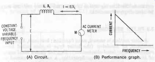
Fig. 1. Basic filtering action of inductor. (A) Circuit. (B) Performance
graph.
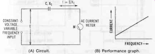
Fig. 2. Basic filtering action of capacitor.(A) Circuit. (B) Performance
graph.
From Figs. 1B and 2B, respectively, it is seen that the inductor tends to transmit low frequencies and attenuate high frequencies, whereas the capacitor tends to attenuate low frequencies and transmit high frequencies. Now, while this simple filtering action is useful, it is limited, for there is no single point (cutoff frequency, f_c) on one side of which frequencies are transmitted with little loss, and on the other side of which frequencies are attenuated. The action is continuous in each case and uniform (Figs. 1B and 2B). When inductors and capacitors are combined, however, into filter sections, each enhances the filtering action of the other. Filter sections may be used singly or cascaded.
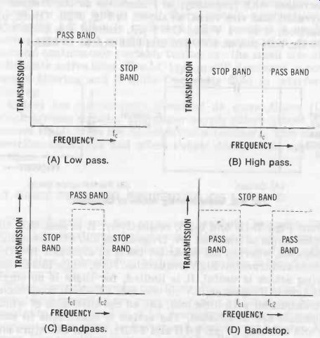
Fig. 3. Ideal filter action. (A) Low pass. (B) High pass. (C) Bandpass.
(D) Bandstop.
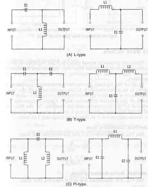
Fig. 4. Basic filter configurations. (A) L-type. (B) T-type. (C) Pi-type.
3.2 FILTER SECTIONS
A filter section is named, as to function: low-pass, high-pass, bandpass, or bandstop (the latter type is also called band suppression or band-elimination). Fig. 3 shows ideal action of these sections. As to configuration, a section is named ac cording to the Greek or Roman letter which its schematic resembles : L, T, or pi. Fig. 4 illustrates these basic con figurations.
Figs. 5 to 15 give circuits and data for L-type low-pass, high-pass, bandpass, and bandstop filter sections. For each of these classes, two types are shown: constant--k and m--derived (both series and shunt type). The constant-k type is the simpler, but performance of the m type more closely approaches the ideal. The constant-k type is so called because the product of the impedance (Z1) of its series arm and the impedance (Z2) of its shunt arm equals a constant: Z1Z2 =k2.
In the m type, the factor m governs the ratio of cutoff frequency f. to a given high-attenuation frequency (the frequency, for instance, at which transmission approaches zero) and generally has the selected value 0.6.
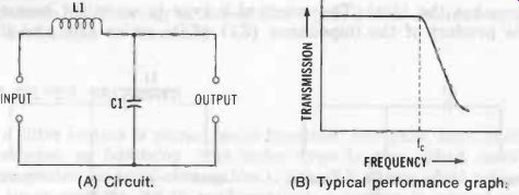
Fig. 5. Low-pass filter (constant-k type). A) Circuit. (B) Typical performance
graph.
3.3 WAVE FILTERS
These are primarily signal filters and are regarded as dissipation-less networks (while this ideal state is unattainable, it can be approached by employing high-Q inductors and capacitors).
In all of the sections shown, the terminating impedance is taken to be a resistance (R in the equations), and the input impedance of the filter assumes the same resistance value over much of the selected frequency band. Cutoff frequencies are selected by the designer to suit his demands for the filter. In all of the equations, inductance L is in henrys, capacitance C in farads, resistance R in ohms, and frequency f in hertz.
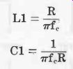
Low-Pass, Constant-k Type See Fig. 5. Equations 3-1 and 3-2 describe this filter.
R L1 =
pi f, 1 C1 =
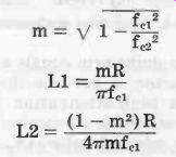
pi fell Low-Pass, Series-Derived m-Type See Fig. 6. Equations 3-3 to 3-6 describe this filter.
(3-1) (3-2)
(3-3) (3-4) (3-5)
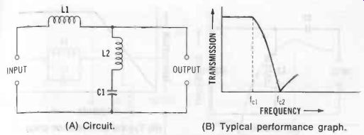
Fig. 6. Low-pass filter (series-derived m-type). (A) Circuit. (B) Typical performance
graph.
(3-6)
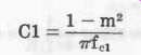
Low-Pass, Shunt-Derived m-Type See Fig. 7. Equations 3-7 to 3-10 describe this filter.
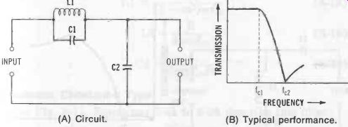
Fig. 7. Low-pass filter (shunt-derived m-type). (A) Circuit. (B) Typical performance.
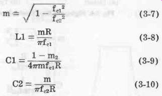
(3-7) (3-8) (3-9) (3-10)
High-Pass, Constant-k Type
See Fig. 8. Equations 3-11 and 3-12 describe this filter.

(3-11)
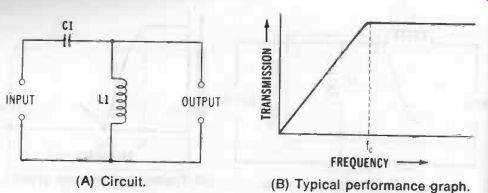
Fig. 8. High-pass filter (constant-k type). (A) Circuit. (B) Typical performance
graph.
High-Pass, Series-Derived m-Type See Fig. 9. Equations 3-13 to 3-16 describe this filter.
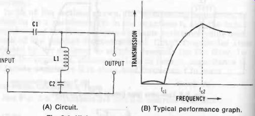
Fig. 9. High-pass filter (series-derived m-type). (A) Circuit. (B) Typical
performance graph.

(3-16)
High-Pass, Shunt-Derived m-Type See Fig. 10. Equations 3-17 to 3-20 describe this filter.
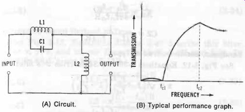
Fig. 10. High-pass filter (shunt-derived m-type). (A) Circuit. (B) Typical
performance graph.
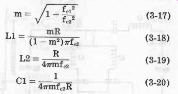
(3-17) (3-18) (3-19) (3-20)
Bandpass, Constant-k Type See Fig. 11. Equations 3-21 to 3-24 describe this filter.
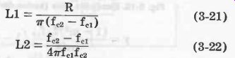
(3-21) (3-22)
Fig. 11. Bandpass filter (constant-k type). (A) Circuit. (B) Typical performance graph.
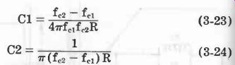
(3-24) (3-23)
Bandpass, Series-Derived m-Type See Fig. 12. Equations 3-25 to 3-34 describe this filter.
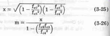
(3-25) (3-26)
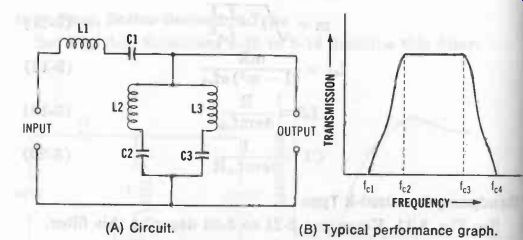
Fig. 12. Bandpass filter (series-derived m-type). A) Circuit. (B) Typical
performance graph.
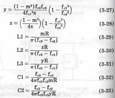
(3-27) (3-28) (3-29) (3-30) (3-31) (3-32) (3-33)

(3-34)
Bandpass, Shunt-Derived m-Type
See Fig. 13. Equations 3-35 to 3-40 describe this filter.
(For x, y, z, and m, see Equations 3-25, 3-27, and 3-28. To identify all fe's, see Fig. 13B.)
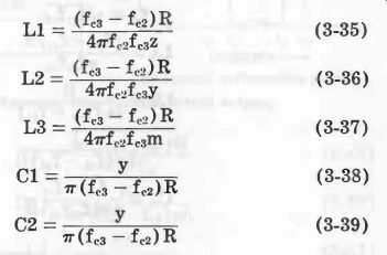
(3-35) (3-36) (3-37) (3-38) (3-39)
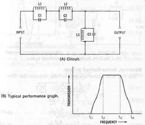
Fig. 13. Bandpass filter (shunt-derived m-type). (A) Circuit. (B) Typical
performance graph.
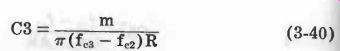
(3-40)
Bandstop, Constant-k Type See Fig. 14. Equations 3-41 to 3-45 describe this filter. (In Equation 3-41 and Fig. 14B, fm is the center frequency of the stopband.)
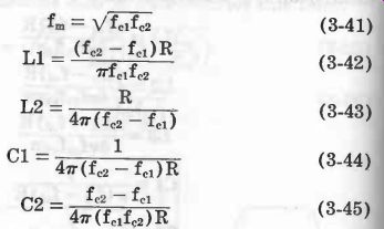
(3-41) (3-42) (3-43) (3-44) (3-45)
Bandstop, Series-Derived m-Type
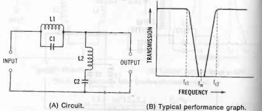
Fig. 14. Bandstop filter (constant-k type). (A) Circuit. (B) Typical performance
graph.
See Fig. 15. Equations 3-46 to 3-54, describe this filter.
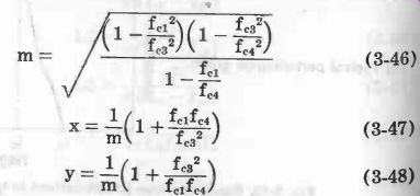
(3-46)
(3-47)
(3-48)
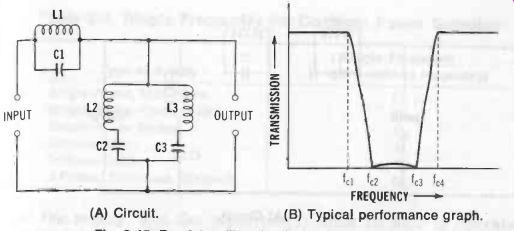
Fig. 15. Bandstop filter (series-derived m-type). (A) Circuit. (B) Typical
performance graph.
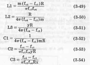
(3-49) (3-50) (3-51) (3-52) (3-53) (3-54)
Bandstop, Shunt-Derived m-Type See Fig. 16. Equations 3-55 to 3-60 describe this filter.
(For m, x, and y, see Equations 3-46, 3-47, and 3-48. To identify all fe's, see Fig. 16B.)
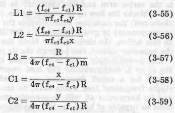
(3-55) (3-56) (3-57) (3-58) (3-59)
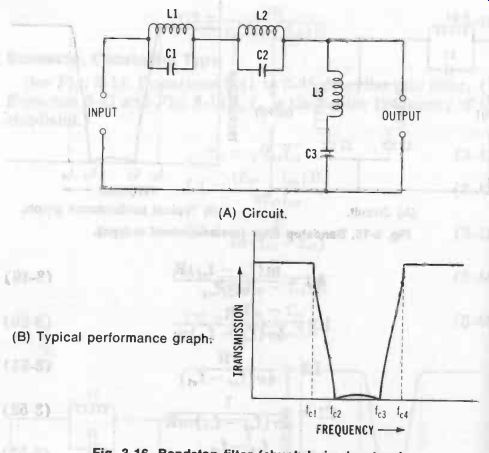
Fig. 16. Bandstop filter (shunt-derived m-type). (A) Circuit. (B) Typical performance
graph
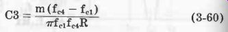
(3-60)

Table 3-1. Ripple Frequency for Common Power Supplies
4. POWER-SUPPLY FILTERS
The purpose of a power-supply filter is to remove the ripple from the dc output of a rectifier. In such a filter, the inductor is the series arm and the capacitor is the shunt arm. The choke blocks the flow of the ripple, hence, its familiar name of choke coil; the capacitor short-circuits the ripple (which is an ac component) to ground, hence, its familiar name of bypass.
In this action, the choke cannot block the de component, and the capacitor cannot short-circuit the dc component.
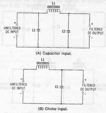
Fig. 17. Typical single-section power-supply filters. (A) Capacitor input.
(B) Choke input.
The power-supply filter is a low-pass circuit, generally of the pi or L configuration. For best results, it should be de signed for a cutoff frequency considerably lower than the ripple frequency (see Table 3-1), to ensure that the ripple and its harmonics all will be severely attenuated. The choke must be capable of handling the maximum direct-current load of the supply, and the capacitor (s) must be able to operate safely at the peak output voltage of the rectifier.
Fig. 17 illustrates the two basic types of single-section power-supply filter. The capacitor-input type (Fig. 17A) provides the higher dc output voltage, which at low output-current level (high load resistance) may approximate the peak value of the ac voltage input to the rectifier (i.e., Ed, = 1.41 but has the poorer voltage regulation. The choke-input type (Fig. 17B) provides lower dc voltage ( Ede = approximately 0.9E,,), but has superior output-voltage regulation.
Note that in each instance an output capacitor is required (C2 in Fig. 17A, C1 in Fig. 17B). Fig. 18 shows typical two-section filters for increased smoothing of dc output. In power-supply filters, capacitors function not only as frequency-selective elements, but also as energy-storage devices : during the rise of the rectified-voltage pulse from zero to maximum, the capacitor charges while current is being delivered to the dc output load ; then, as the voltage subsequently decreases to zero, the capacitor discharges, delivering its energy to the output load and thus maintaining the filter output voltage constant.
A cursory inspection of Figs. 17 and 18 shows that the filters all are low-pass, constant-k type. Their design accordingly may be accomplished with the aid of Equations 3-1 and 3-2. (Load R in these formulas will be an actual resistance to which the power supply delivers energy or will be the quotient E /I, where E is the de load voltage in volts, and I is the dc load current in amperes.) For some applications, the design procedure is bypassed completely. Instead, on-hand high-inductance chokes and high-capacitance capacitors simply are teamed up. The resulting cutoff frequency generally is so low that the filter is effective in a large number of possible applications. Such an arrangement is familiarly termed a brute-force filter.
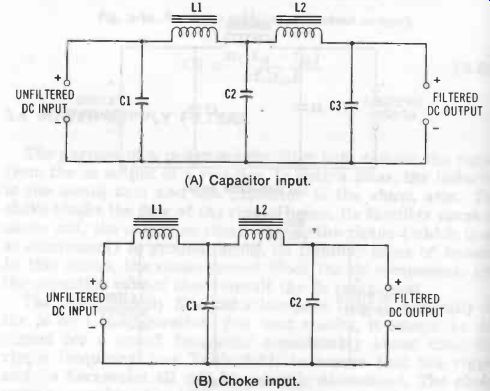
Fig. 18. Typical cascaded filters. (A) Capacitor input. (B) Choke input.
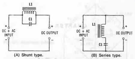
Fig. 19. Resonant single-frequency filters. (A) Shunt type. (B) Series type.
Occasionally, a single frequency-such as a troublesome harmonic of the ac-supply frequency-must be removed from the output of a rectifier. Simple LC combinations for performing this task are shown in Fig. 19. In Fig. 19A, a shunt L1C1 circuit traps the signal; in Fig. 19B, a series L1C1 circuit short-circuits the signal to ground. These arrangements are seldom satisfactory as the complete filter for a power sup ply, since they remove only one frequency (at best a very narrow band of frequencies), but they are very effective when used in conjunction with a regular power-supply filter. Both are immediately recognized as the simple wavetraps described in Section 2.12, Section 2.