AMAZON multi-meters discounts AMAZON oscilloscope discounts
Inductance-capacitance combinations are often seen in oscillators and signal generators, where they function as tanks and filters, and in special-purpose meters, where they serve as selective filters and as tuners. They are also the basis of other test equipment in which an unknown inductance is compared with a known capacitance, such as ac bridges (in combination with resistance), frequency meters (e.g., the absorption wavemeter already described in Section 2.13), and component testers using the resonance method.
This Section describes several of the better-known LC-based test and measuring devices.
4.1 ANDERSONBRIDGE
See Fig. 1. This is a six-impedance network (L., Cs, R1, R2, R3, R4) in which unknown inductance L. is compared with standard capacitance Cs. Although harder to adjust than the more common four-impedance bridges, this circuit offers a wider range.
The inductance balance (R3) and Q balance (R1) are independent of each other and of the generator frequency. At null :
L. = Cs [R3 ( 1 + R2/R4 ) + R2] (4-1)
where, L. is in henrys, Cs is in farads, All Rs are in ohms.
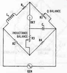
Fig. 1. Anderson bridge.
The equivalent resistance (R.) of the inductor under test is calculated:
R = (R1R2) R4 (4-2)
4.2 HAYBRIDGE
See Fig. 2. In this bridge, unknown inductance L. is compared with standard capacitance Cs. The circuit is balanced in the conventional manner by alternate adjustment of inductance-balance rheostat R2 and Q-balance rheostat R3. At null:
= R1R2R3 1 + (R32(02C82) where, L. is in henrys, Cs is in farads, 0) is 2 pi f (f is in hertz), All Rs are in ohms.
(4-3)
Since R3 appears in the denominator of the fraction, the inductance balance is not independent of the Q balance. Also, since a) also appears in the equation, the balance is frequency dependent. However, if the Q of the inductor under test is higher than 10, the frequency may be ignored, and Equation 4-3 may be simplified with an error of less than 1 percent :
L. = CB(R1R2) (4-4)
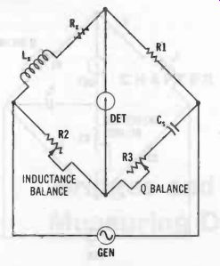
Fig. 2. Hay bridge.
At null, the equivalent resistance (R8) of the inductor under test is calculated:
R. _ co2C82R1R2R3 1 + (co2C82R32
gain note that the settings of both the inductance-balance rheostat (R2) and Q-balance rheostat (R3) enter into the calculation and that the R. determination, like that of L., is frequency dependent. However, if the Q of the inductor is higher than 10, Equation 4-5 may be simplified:
4.3 MAXWELLBRIDGE
(4-5)

(4-6)
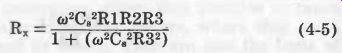
See Fig. 3. This circuit compares unknown inductance L.
with standard capacitor C8. It differs from the Hay bridge described in the preceding section in the parallel connection of the Q-balance rheostat (R3) and standard capacitor (C8).
In this bridge, the inductance balance and Q balance are independent of each other and each is independent of frequency. At null:
L. = Cs (R1R2)

(4-7)
where, L. is in henrys, C8 is in farads, Both Rs are in ohms.
Fig. 3. Maxwell bridge.
The equivalent resistance (R8) of the inductor under test is calculated:
R. = R1 (R2) R3
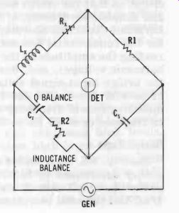
Fig. 4. Owen bridge.
4.4 OWEN BRIDGE

(4-8)
See Fig. 4. In this circuit, a variable capacitor (Cr) is employed as the Q-balance component. The inductance balance and Q balance are independent of each other and each is independent of frequency. The Owen bridge provides an extremely wide inductance range for a narrow range of Cs and R values.
At null :
L, = (R1R2) (4-9).
where, L is in henrys, Cs is in farads, Both Rs are in ohms.
The equivalent resistance (R,) of the inductor under test is calculated :
Rx = R1 (--tC Cr) where, R, and R1 are in ohms, Cr and Cs are in farads.
4.5 RESONANCE BRIDGES

(4-10)
While frequency sensitivity can be somewhat of a nuisance in ac bridges used for inductance, capacitance, and resistance measurements, this property may be utilized for the measurement of frequency if all of the bridge arms are filled and the bridge then is balanced for frequency. In such an instance, the balance-adjustment component (rheostat or variable capacitor) may be made direct reading in frequency instead of in R, C, or L. The resistance, capacitance, and/or inductance values in the bridge arms usually can be known with high precision, so that the bridge becomes a useful device for accurate and simple measurement of frequency. Measurements of total harmonic distortion also may be made by balancing the bridge for the fundamental frequency of a complex test signal, then reading the amplitude of the output at null (which is the total harmonic voltage), and, finally, comparing this voltage with the bridge input-signal voltage. The resonance bridge is one of several types used for these purposes. Resonance-bridge measurements of frequency and distortion are usually limited to frequencies of 20 Hz to 20 kHz.
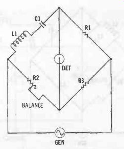
Fig. 5. Resonant bridge (series type).
Series Type
See Fig. 5. This bridge may be balanced only at the frequency determined by inductance L1 and the capacitance C1 in the upper left arm of the circuit. At this frequency, coL =1/o)C and the total reactance = 0, and only the internal resistance of the inductor and capacitor remain in that arm, making the circuit a four-arm resistance bridge at that one frequency. At null, the unknown frequency is :

fx=1/2 pi _/L1C1
(4-11)
where, fx is in hertz, L1 is in henrys, C1 is in farads, pi is 3.1416.
A desired frequency spectrum may be covered by making C1 variable for tuning, and by switching L1 to appropriate values to change ranges. (Since high capacitances are needed for the audio spectrum where the resonance bridge is effective, a variable C1 would for practical purposes be a capacitor decade.) For sharp null response, both C1 and L1 must be high-Q components.
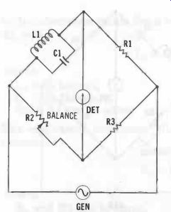
Fig. 6. Resonance bridge (shunt type).
Shunt-Type
See Fig. 6. Because the impedance arm in the series-type circuit (Fig. 5) is a series-resonant circuit, the current through this arm and the one containing resistor R1' is maximum at the resonant frequency and can reach high levels.
With some inductors, especially when high input-signal voltage and low values of R1 are unavoidable, the resulting high current can introduce enough distortion to obscure the null.
To eliminate these difficulties, the impedance arm has been changed in Fig. 6 to a shunt connection of the inductance and capacitance (parallel-resonant circuit). In this arrangement, the current through the impedance arm and R1 is minimum at resonance, approaching zero for high-Q inductors and capacitors. In all other respects, the shunt-type bridge is identical to the series type described in the preceding section. The balance equation likewise is the same (see Equation 4-11).
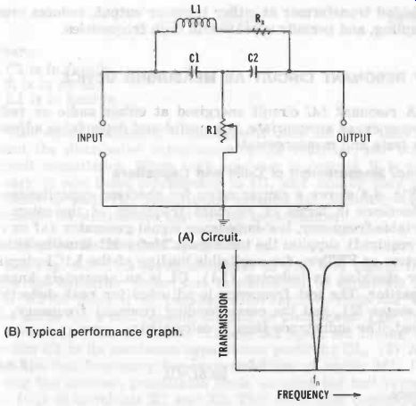
Fig. 7. Bridge null network. (B) Typical performance graph.
4.6 BRIDGED-T NULL NETWORK
The circuit shown in Fig. 7A provides a sharp null when high-Q inductor and capacitors are employed. It takes its name from the fact that inductor L1 bridges the T network formed by capacitors C1 and C2 and resistor R1. In the inductive arm of the circuit, Rx is the equivalent series resistance of the inductor. Capacitances C1 and C2 are made equal and may be varied simultaneously to tune the network. (Alternatively, the capacitors may be held at a fixed value, and the inductance varied.) To balance the network, the capacitances (or inductance) and resistance R1 must be adjusted alternately, C1 being equal to C2 at all points. At null :
fn = 1/ pi _/ [2L1C1]
where, fn is in hertz, L1 is in henrys, C1 is in farads, pi is 3.1416.
(4-12)
The equivalent resistance (Rx) of inductor L1 is calculated:
1 R, = (4-13) R1 (c0C1) 2
where,
Rx and R1 are in ohms,
C1 is in farads,
omega is 2 pi f (f is in hertz).
The bridged-T network is used for frequency measurements and distortion measurements in the same manner as explained for the resonance bridge (Section 4.5). It may be used also for capacitance measurement (C1 or C2 = 1/8 pi^2 f^2L), or inductance measurement (L1 = 1/2 pi^2 f^2 C1). In this function, it is used as high as the lower vhf spectrum. This device also finds wide use as a bandstop filter (notch filter). An advantage of the bridged-T network over an equivalent bridge, when it can be used, is its provision of a common ground for generator, network, and detector. This removes the need for a shielded transformer at either input or output, reduces cross coupling, and permits operation at high frequencies.
4.7 RESONANT CIRCUIT AS MEASURING DEVICE
A resonant LC circuit energized at either audio or radio frequency, as appropriate, is a useful and dependable adjunct for tests and measurements.
Direct Measurement of Coils and Capacitors
Fig. 8 shows a simple setup for checking capacitance or inductance in terms of resonant frequency of the setup. A variable-frequency, low-impedance signal generator (af or rf, as required) supplies the test signal. Meter M1 must be either a vtvm or FETvm, for negligible loading of the L1C1 circuit.
For checking an inductor (L1), C1 is an accurately known capacitor. The test frequency is adjusted for peak deflection of meter Ml, and the corresponding resonant frequency, fr, noted. The inductance then is calculated:
where, L1 is in henrys, fr is in hertz, C1 is in farads.

(4-14)
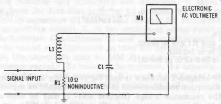
Fig. 8. Resonant circuit for component testing.
For checking a capacitor (C1), L1 is an accurately known inductor. The test frequency is adjusted for peak deflection of meter Ml, and the corresponding resonant frequency, fr, noted. The capacitance then is calculated:

(4-15)
…where, C1 is in farads, fr is in hertz, L1 is in henrys.
This direct method of measurement does not take into ac count the distributed capacitance of the inductor, nor stray circuit capacitance. When high accuracy is desired, it is necessary to add these components to C1, and usually they are difficult to find. The substitution method automatically compensates for distributed and wiring capacitances.
Substitution Method for Capacitors
See Fig. 9. This setup is similar to Fig. 8, except that here the capacitor under test is connected to terminals X1 and X2 to place it in parallel with variable capacitor C1.
The latter has a dial reading directly in picofarads.
Test Procedure: (1) With terminals X1 and X2 open, set tuning capacitor C to its maximum-capacitance position: C1. (2) Ad just the test frequency for peak deflection of meter M1. (3) Using the shortest practicable leads, connect the test capacitor (C1) to terminals X1 and X2. This additional capacitance detunes the circuit, causing the meter reading to fall. (4) De-tune C1 to restore peak deflection. (5)
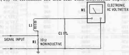
Fig. 9. Resonant circuit for substitution-type capacitance measurement.
At this point, read the new capacitance setting: C1b. (6) Calculate the unknown capacitance:
Cx = C1a-C1b
(4-16)
The substitution method has the disadvantage that it is limited to capacitances that do not exceed the maximum capacitance (C1) of tuning capacitor C1.