To draw a graph, your scope needs horizontal as well as vertical data. The horizontal system of your scope supplies the second dimension by providing the deflection voltages to move the electron beam horizontally. And the horizontal system contains a sweep generator which produces a sawtooth waveform, or ramp (see Fig. 7), that's used to control the scope’s sweep rates.
AMAZON multi-meters discounts AMAZON oscilloscope discounts
Because all 2200s are two-channel scopes, you will have one set of these switches for each channel. There are also two switches for choosing the scope’s vertical display mode and one control that allows you to invert the polarity of the channel 2 signal.
It’s the sweep generator that makes the unique functions of the modern oscilloscope possible. The circuit that made the rate of rise in the ramp linear — a refinement pioneered by Tektronix— was one of the most important advances in oscillography. It meant that the horizontal beam movement could be calibrated directly in units of time. That advance made it possible for you to measure time between events much more accurately on the scope screen.
Because it's calibrated in time, the sweep generator is often called the time base. It lets you pick the time units, observing the signal for either very short times measured in nanoseconds or microseconds, or relatively long times of several seconds.
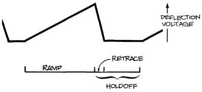
Above: Figure 7. a sawtooth waveform, or ramp. THE SAWTOOTH WAVEFORM is a
voltage ramp produced by the sweep generator. The rising portion of the waveform
is called the ramp; the falling edge is the retrace; and the time between
ramps is the holdoff time. The sweep of the electron beam across the screen
of a scope is controlled by the ramp and the return of the beam to the left
side of the screen takes place during the retrace.
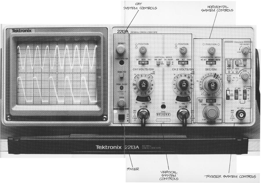
The horizontal-system controls of a Tektronix 2213A scope are shown here.:
Click here for larger, labeled image of
the Tektronix 2213.
The horizontal POSITION control is near the top of the panel, and the HORIZONTAL MODE control is below it; the magnification and variable sweep speed control is a red knob in the center of the SEC/DIV switch; at the bottom of the column of horizontal system controls are the DELAY TIME switch and the delay time MULTIPLIER. The dual time base 2215A has two concentric SEC/DIV controls, and a B DELAY TIME POSITION control instead of the delay time switch and multiplier. (The scope controls that you use to position the start of a delayed sweep are also often called delay time multipliers or DTMs.)
Horizontal Position
Like the vertical POSITION controls, you use the horizontal POSITION control to change the location of the waveforms on the screen.
Horizontal Operating Modes
Single time base scopes usually have only one horizontal operating mode, but the 2213A offers normal, intensified, or delayed-sweep operating modes. Dual time base scopes like the 2215A usually let you select either of two sweeps. The A sweep is undelayed (like the sweep of a single time base instrument), while the B sweep is started after a delay time. Additionally, some scopes with two time bases—and the 2215A is an example again—let you see the two sweeps at once: the A sweep intensified by the B sweep; and the B sweep itself. This is called an alternate horizontal operating mode.
Only the normal horizontal operating mode is used in these first few Sections, so leave your scope’s HORIZONTAL OPERAT ING MODE switch in NO DLY (no delay) on the 2213A and A (for A sweep only) on the 2215A. Section 9, in the second section of this primer, describes how to make delayed sweep measurements.
Sweep Speeds
The seconds/division switch lets you select the rate at which the beam sweeps across the screen; changing SEC/DIV switch settings allows you to look at longer or shorter time intervals of the input signal. Like the vertical system VOLTS/DIV switch, the control’s markings refer to the screen’s scale factors. If the SEC/DIV setting is 1 ms, that means that each horizontal major division represents 1 ms and the total screen will show you 10 ms.
On the 2215A, which has two time bases, there are two SEC/ DIV controls. The A sweep offers all the settings described below the SEC/DIV switch for the delayed B sweep has settings for 0.05 micro-sec/div to 50 ms/div.
All the instruments of the Tektronix 2200 Series offer sweep speeds from a half-second for each division to 0.05 µS/ division. The markings appearing on the scopes are:
5 S .2 S .1 S 50 ms 20 ms 10 ms 5 ms 2 ms 1 ms .5 ms .2 ms .1 ms 50 µS 20 µS 10 µS 5 µS 2 µS 1 µS .5 µS .2 µS .1 µS .05 µS |
half a second 0.2 second 0.1 second 50 milliseconds (0.05 second) 20 milliseconds (0.02 second) 10 milliseconds (0.01 second) 5 milliseconds (0.005 second) 2 milliseconds (0.002 second) 1 millisecond (0001 second) half a millisecond (0.0005 second) 0.2 millisecond (0.0002 second) 0.1 millisecond (0.0001 second) 50 microseconds (0.00005 second) 20 microseconds (0.00002 second) 10 microseconds (0.00001 second) 5 microseconds (0.000005 second) 2 microseconds (0.000002 second) 1 microsecond (0.000001 second) half a microsecond (0.0000005 second) 0.2 microsecond (0.0000002 second) 0.1 microsecond (0.0000001 second) 0.05 microseconds (0.00000005 second) |
Scopes also have an X-Y set ting on the SEC/DIV switch for making the X-Y measurements described in Section 9.
Variable SEC/DIV
Besides the calibrated speeds, you can change any sweep speed by turning the red CAL control in the center of the SEC/DIV switch counterclockwise. This control slows the sweep speed by at least 2.5:1, making the slowest sweep you have 0.5 seconds x 2.5, or 1.25 seconds/division. Remember that the detent in the extreme clockwise direction is the calibrated position.
Horizontal Magnification
Most scopes offer some means of horizontally magnifying the waveforms on the screen. The effect of magnification is to multiply the sweep speed by the amount of magnification. On 2200 Series scopes there is a 10x horizontal magnification that you engage by pulling out on the red CAL switch. The 10x horizontal magnification gives you a sweep speed ten times faster than the SEC/DIV switch setting; for example, 0.05 uS/division magnified is a very fast 5-nanosecond/division sweep.
The 10X magnification is useful when you want to look at signals and see details that occur very closely together in time.
The DELAY TIME and MULTIPLIER Controls This switch and dial are used in conjunction with either the intensified or delayed-sweep horizontal operating modes in the 2213A. These features are described later under Delayed Sweep Measurement” in Section 9.
The B DELAY TIME POSITION Control
This calibrated 10-turn dial is used to position the beginning of the B sweep relative to the A sweep in a 2215A. Its uses are described under “Delayed Sweep Measurements in Section 9.
Using the Horizontal Controls
As you can see in Figure 8, the horizontal system can be divided into two functional blocks: the horizontal amplifier and the sweep generator.
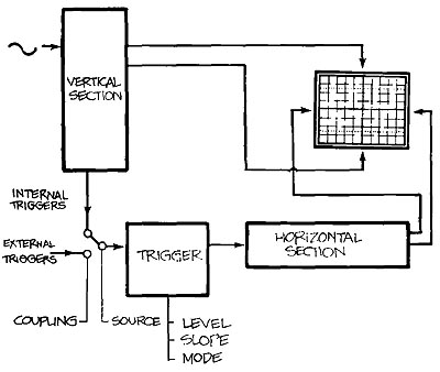
Figure 8. HORIZONTAL SYSTEM components include the sweep generator and the
horizontal amplifier. The sweep generator produces a sawtooth waveform that's processed by the amplifier and applied to the horizontal deflection
plates of the CRT The horizontal system also provides the Z axis of the scope;
the Z axis determines whether or not the electron beam is turned on — and how bright it's when it’s on.
To familiarize yourself with the horizontal system controls, follow the directions in Exercise 4 and refer to this illustration for control locations. First, make sure the front panel controls have these settings:
• the SEC/DIV switch is on 0.5 ms;
• the trigger SOURCE (A TRIG GER SOURCE on the 2215A) is INT; INT (2215A: A&B INT) is on CH 1;
• the trigger MODE (2215A: A TRIGGER MODE) is P-P AUTO;
• the channel 2 INVERT switch is out (no signal inverting);
• and HORIZONTAL MODE is NO DLY (A on the 2215A)
Exercise 4. THE HORIZONTAL SYSTEM CONTROLS
1. Switch the VERTICAL MODE to CH 1 and the CH 1 VOLTS/DIV setting to 0.5 volt. Be sure your probe is connected to channel 1 and the PROBE ADJ jack. Turn on your scope and move the channel 1 input coupling lever to GND and center the signal on the screen with the POSITION control. Switch to AC coupling.
2. Now you can use the horizontal system of your scope to look at the probe adjustment signal. Move the waveform with the horizontal POSITION control until one rising edge of the waveform is lined up with the center vertical graticule. Examine the screen to see where the leading edge of the next pulse crosses the horizontal center line of the graticule. Count major and minor graticule markings along the center horizontal graticule and remember the number.
3. Change sweeps to 0.2 ms, line up a rising edge with the vertical graticule on the left edge of the screen and count to the next rising edge. Because the switch was changed from 0.5 to 0.2 ms, the waveform will look 2.5 times as long as before. Of course, the signal hasn’t changed, only the scale factor.
4. In the middle of the SEC/DIV switch is the red variable control; in its counterclockwise de tent, the settings of the SEC/DIV switch are calibrated. Move the control from its detent to see its effect on the sweep speed. Note that now the cycles of the wave form are approximately two- and -a -half times smaller. Return the CAL control to its detent.
5. Move the SEC/DIV switch to 0.5 ms and then pull out the red CAL control. This gives you a lox magnification of the sweep speed. In other words, every setting on the SEC/DIV switch will result in a sweep that’s ten times faster; for example, the sweep now is 0.05 ms/division, not 0.5 ms.
6. While your scope is magnifying the probe adjustment signal, use the horizontal POSITION control. Its range is now magnified as well, and the combination of magnified signal and POSITION control gives you the ability to examine small parts of a waveform in great detail. Return your scope to its normal sweep speed range by pushing the CAL switch in.